Thornwave Labs BT-DCPM User manual

Thornwave Labs Inc –A smart device company –Raleigh, NC, 1-888-399-WAVE
Bluetooth Smart Battery Monitor / DC Power Meter
–BT-DCPM –
Quickstart Guide
This document is meant to be a quick start guide for installing and configuring the BT-DCPM,
Bluetooth Battery Monitor / DC Power Meter and does not contain in-depth details. For a complete
manual please visit the product webpage at https://www.thornwave.com/products-btdcpm
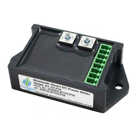
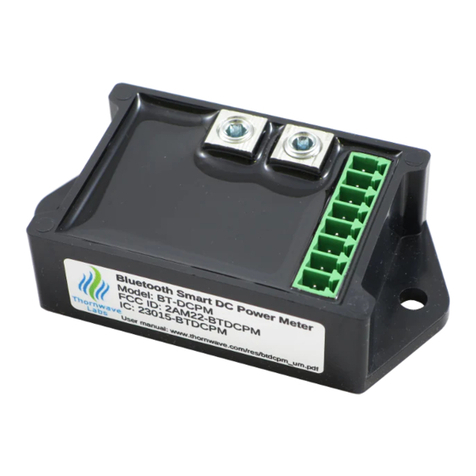
Package contents. The product has been shipped in a white box containing the BT-DCPM device,
an 8-pin female terminal block and a short piece of copper wire. From the factory, the device is
configured to use the internal current shunt. All extra features are in the disabled state. No calibration
has been applied to the current reading. If higher accuracy is required, please read the “Calibration”
section.
Required tools / materials. To complete the installation of the BT-DCPM device the following
tools and materials are required:
•wire cutters
•wire strippers
•small flat screwdriver
•long nose pliers
•external current shunt (if applicable)
•6AWG wire for the high current connections (the aluminum set screw terminal blocks on
the device). If using an external shunt larger wire may be required.
•16-22 AWG wire for wiring the other signals. Different colors are recommended (red /
black / green / yellow / blue)
•2 screws (for mounting the device on a flat surface). These can be metal screws, wood
screws or screws meant for plastic inserts, depending on the surface the device will be
mounted on. The device can also be mounted using double sticky tape or even plastic zip-
ties.

Thornwave Labs Inc –A smart device company –Raleigh, NC, 1-888-399-WAVE
SAFETY INSTRUCTIONS
Warning !
Read all the instructions and cautions before using the BT-DCPM device. Thornwave Labs Inc.
does not assume responsibility for any injury or property damage caused by improper installation, bad
wiring or use of BT-DCPM outside of its intended purpose. The device should be installed by a
professional.
Warning !
The BT-DCPM device should not be used for any medical purposes, life sustaining equipment,
safety applications or any application where equipment failure can cause injury, death, fires, or any other
hazard.
Warning !
There are no serviceable parts or fuses inside the power meter! Do not disassemble or attempt
to repair! The unit operates with voltages up to 60V which can be lethal or cause serious and permanent
injury.
Warning !
Do not submerge under water or other liquids. The device is weatherproof but not waterproof.
Warning !
The power meter is to be connected to DC circuits only, not exceeding 60V or 60A (using the
internal current shunt). Failure to do so will result in equipment damage. Higher currents are supported
when using an external current shunt. Confirm that all connections are tight to avoid excessive heating
and sparks. Never connect the V1 or VS terminals to a power source without using a fuse or circuit
breaker. A 0.1A to 5A fuse or circuit breaker is required.
Warning !
Batteries are dangerous! Do not short-circuit a battery or the power meter. Batteries can produce
flammable and explosive gases and can generate very high currents that can lead to serious
consequences including explosion, fire, damage to equipment, personal injury and even death. It is the
user’s responsibility to operate the equipment in a safe manner. Do not charge batteries in an enclosed
environment unless allowed by the manufacturer of the battery. Never connect a load to a battery
without using fuses or circuit breakers.

Thornwave Labs Inc –A smart device company –Raleigh, NC, 1-888-399-WAVE
TERMINAL DESCRIPTION / INTERNAL DIAGRAM
No.
Name
Terminal Description
1
GROUND
System Ground
2
MF
Multi-function (for hardware revision 2.2 and up)
3
RELAY
Relay output - Used to control a mechanical or solid-state relay. This
terminal is connected to ground internally in order to turn the relay
on.
4
ES+
External Shunt connection (positive side). When using the internal
current shunt connect this terminal to ES- (terminal 5)
5
ES-
External Shunt connection (negative side). When using the internal
current shunt connect this terminal to ES+ (terminal 4)
6
VS
Optional power supply. If available, connect this terminal to a power
supply of no more than 18V. This connection is optional.
7
V2
Second monitored voltage. Used to monitor a second battery.
8
V1
Main power. This is the main voltage that will be monitored. The
device also draws its power form this terminal. If power is applied to
terminal 6 (VS), the device will draw its power from VS instead of V1.
9
IS-
Internal Shunt connection (negative side). Do not connect if using an
external shunt. If the internal shunt is used, the measured current
will be entering or exiting this terminal.
10
IS+
Internal Shunt connection (positive side). Do not connect if using an
external shunt. If the internal shunt is used, the measured current
will be entering or exiting this terminal.

Thornwave Labs Inc –A smart device company –Raleigh, NC, 1-888-399-WAVE
Mounting the device
•WARNING! Do not work on a live electrical system. Disconnect the power source first!
•Attach the device to a flat surface using two screws, double sticky tape or plastic zip-ties
•Mounting on a metallic surface or inside a metal enclosed space will substantially reduce the
Bluetooth range. For best results mount in such a way so the radio signal will not be blocked.
Keep in mind that at the Bluetooth frequency of 2.4GHz the radio signal travels only in a
straight line and any obstacle in its path (walls, big metal objects) will interfere with it.
•If an external shunt is used, mount it as close as possible to the BT-DCPM device. The longer the
wires that connect the external shunt to the device the more electrical noise they will pick up.
Wiring using the internal shunt (optional)
•If using the internal shunt, connect terminals 4 and 5 together using the piece of copper wire
that was supplied with the device. Cut a shorter piece of the supplied wire and using the long
nose pliers, bend it in a U shape. Insert it into terminals 4 and 5 and tighten the terminals.
•Connect the 6 AWG high current carrying wires to terminals 9 and 10. When current circulates
from terminal 10 towards terminal 9, the device will display a positive value. A reversed current
will display as a negative value. If the measured current has the wrong sign, there is no need to
reverse the wires. The current sign can be flipped through the device configuration.
Wiring using an external shunt (optional)
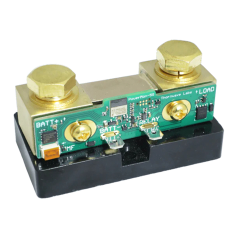
•If using an external shunt connect terminals 4 and 5 to the measurement points on the shunt.
Typically, these are smaller screws positioned inside of the larger high current lugs. Keep the
wires as short as possible. Twisting them will reduce the noise even further. Avoid running
these wires parallel to high current carrying wires. Doing so will introduce unwanted noise into
the measurements. If the measured current has the wrong sign, there is no need to reverse the
wires. The current sign can be flipped through the device configuration.
•Connect the high current lugs of the external current shunt using wires of adequate size.
Crimping of battery lugs may be required. Do not connect terminals 9 and 10!
Device power / voltage measurements
•Using a piece of black wire, connect terminal 1 to the system ground (negative side of the
battery / solar panels / power source)
•Using a piece of red wire connect terminal 8 (V1) to the positive side of the power source using
a fuse or circuit breaker. The maximum current the device will draw is 10mA.
•If applicable, connect terminal 7 (V2) to the second battery (or node in the system) that will be
monitored
•If used in a 12V system, optionally connect terminal 6 (VS) to +12V. The device will now draw its
power from this terminal instead of V1.

Thornwave Labs Inc –A smart device company –Raleigh, NC, 1-888-399-WAVE
External relay (optional)
•If an external relay is used, connect one side of the coil to terminal 3 (RELAY) and the other side
to the power for the relay. This can be the battery, output of a voltage regulator or power
supply not exceeding 18V.
Check all connections again. Verify that the high current wires are tight. Use fuses or circuit breakers
where applicable. Once all these have been checked, insert the female terminal block into the device
and reconnect the battery or the power source. The device should start and become visible on any
mobile device that supports Bluetooth Smart (LE) and is running the PowerMon app.
Mobile application
•Install the mobile application (PowerMon) on your device. This is available for free on Google
Play Store and Apple App Store. Once the application starts it should discover the BT-DCPM
devices that are in range.
•Tap on a device to connect to it. If you are not sure which device is the one you wish to connect
to, you can use the RSSI indicator and position the mobile device very close to the device you
would like to identify. The RSSI will indicate a much stronger signal for that device. Note that
the RSSI values are negative. -30dBm is a stronger signal than -60dBm.
•Once connected tap on the top right corner on the 3 dots (application menu) and then tap on
”About” (Android only). Tap on the rename icon to rename the device. The default name is
“DCPM”. Note that the name cannot be longer than 8 characters.
•This would also be a good time to check for an updated firmware and update if applicable.
During the firmware update process there should be no current flowing through the device.
Disconnect the current shunt wires if required.
•Tap on the application menu again and then “Configuration” (Android only) or on the
configuration icon located to the left of the application menu (iOS)
•Configure the device appropriately (external shunt resistance value, voltage drop range). From
the factory, the device is already configured to use the integrated shunt.
Calibration (optional)
•The only measurement that can be calibrated by the user is the current. If a higher accuracy
than an uncalibrated device offers (about 2%) is required, proceed with the device calibration.
•Make sure the current that passes through the device (terminals 9 and 10) or through the shunt
is zero (no current)
•Long-tap on the current measurement and select “Zero Current”. This will bring the
measurement value to zero.
•Apply a known current (accurately measured using an external am-meter)
•Long-tap on the current measurement again and this time select “Calibrate Current”
•Type the actual value of the current and press OK.

Thornwave Labs Inc –A smart device company –Raleigh, NC, 1-888-399-WAVE
TROUBLESHOOTING
Symptom: The device indicates an awkward current reading but there is no current flowing through it
(or the external shunt)
Possible Causes:
•If using the integrated shunt, terminals 4 and 5 may not be connected together. To fix this,
connect terminals 4 and 5 together.
•If the user performed the "Zero Current”procedure, the device assumed that the external
current was zero and applied an offset to the measurement in order to bring the indicated
value to zero. If the actual device current was not zero at the time the “Zero Current” was
performed, the offset applied will not be correct which leads to the wrong reading. To fix this,
make sure the actual current is zero (disconnect the current wires if required) and execute the
“Zero Current” procedure again.
Table of contents
Other Thornwave Labs Measuring Instrument manuals
