BUSCH VACTEST DTP 400 C User manual

Get technical data,
instruction manuals,
service kits
Instruction Manual
VACTEST
Vacuum Measurement Equipment
Digital Transmitter DTP 400
Digital Transmitter DTP 400 C
0870205259/-0001_en / Original instructions / Modifications reserved 16/09/2021

Table of Contents
2 / 24 Instruction Manual VACTEST DTP 400_EN_en
Table of Contents
1 Safety .......................................................................................................................................3
2 Product Description ..................................................................................................................4
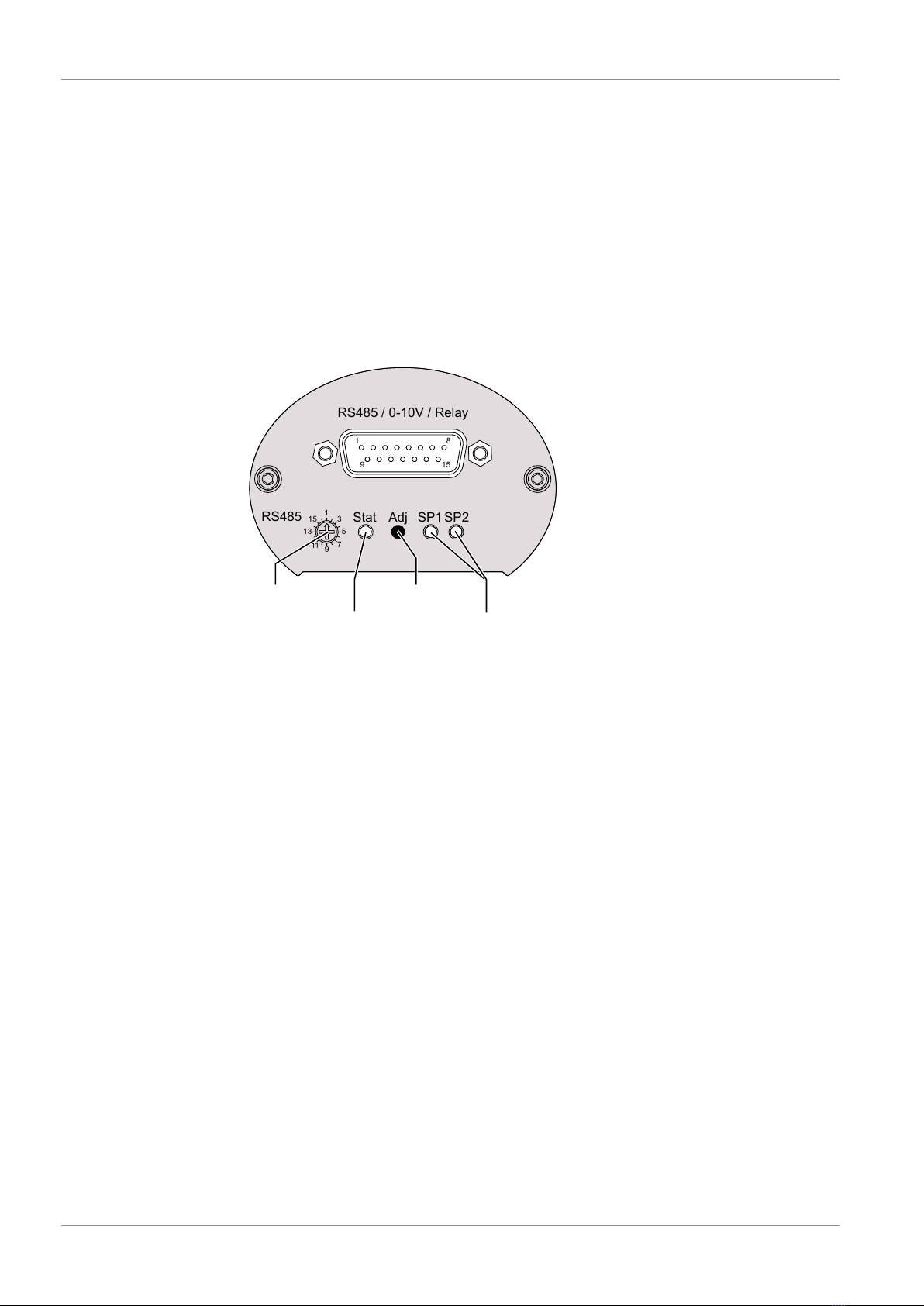
2.1 Interface Illustration ......................................................................................................... 4
2.2 Product Identification ....................................................................................................... 4
2.3 Delivery Content .............................................................................................................. 4
2.4 Proper Use ....................................................................................................................... 4
2.5 Improper Use ................................................................................................................... 4
3 Transport and Storage...............................................................................................................5
4 Installation................................................................................................................................5
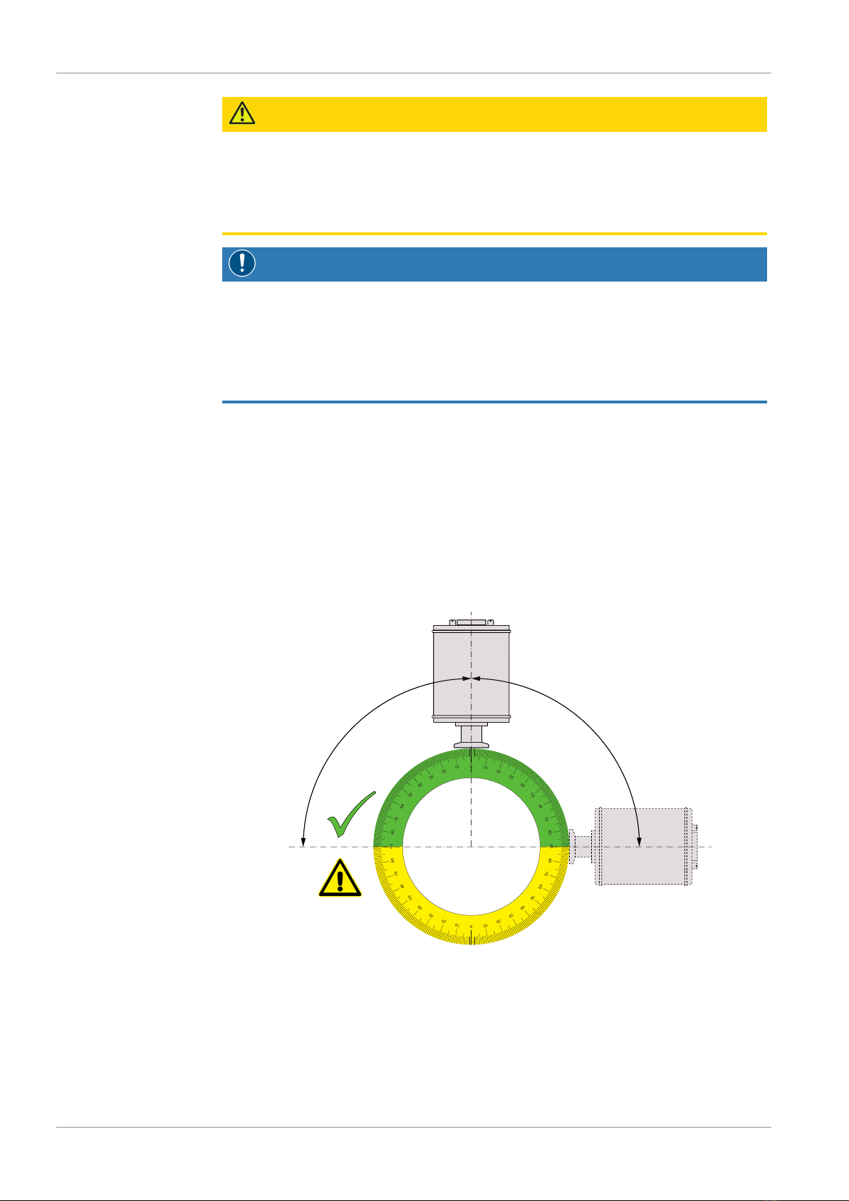
4.1 Installation Conditions...................................................................................................... 5
4.2 Vacuum Connection......................................................................................................... 5
4.3 Electrical Connection ........................................................................................................ 7
4.3.1 Connecting to the Active Sensor Controller ........................................................... 7
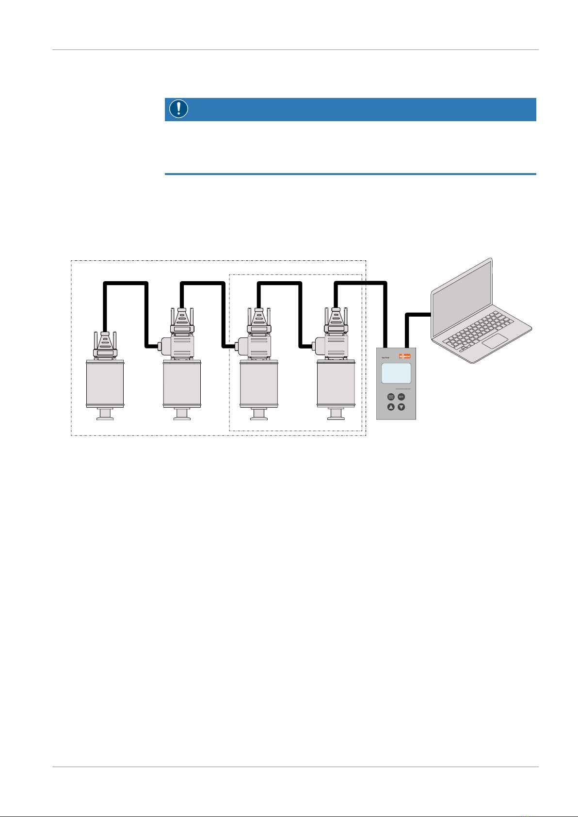
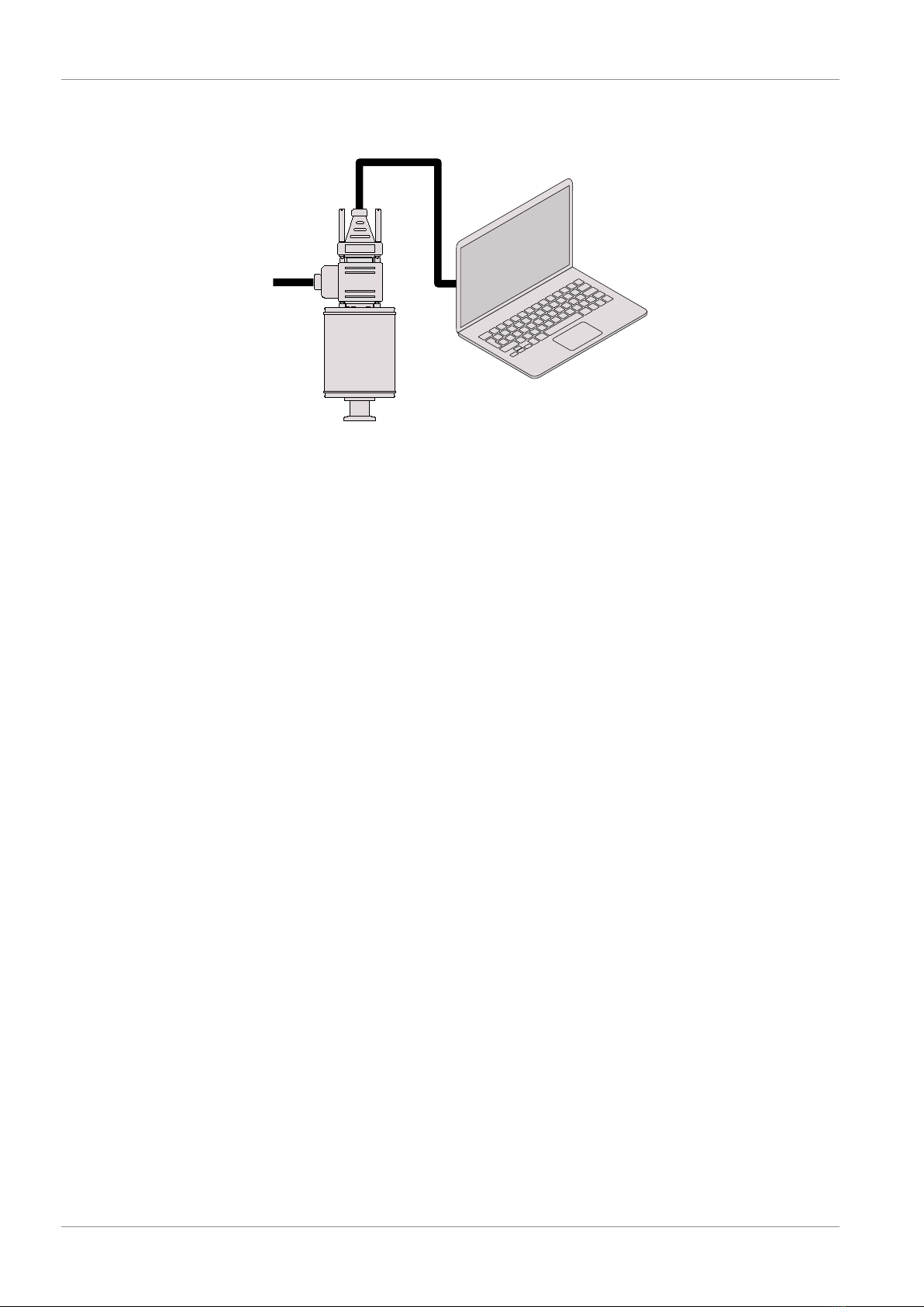
4.3.2 Connecting to the USB/RS485 Converter .............................................................. 8
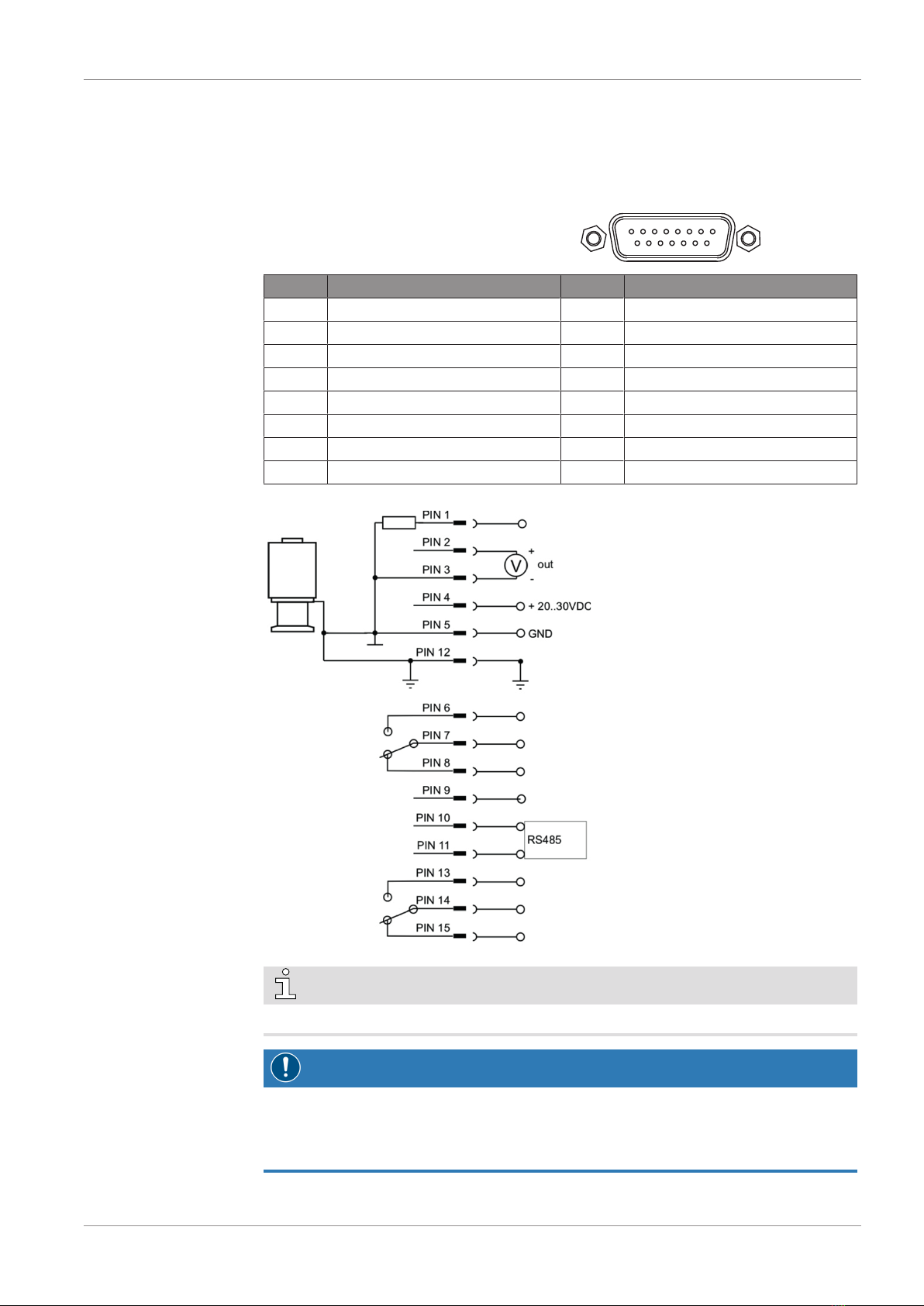
4.3.3 I/O and Communication Port Schematic ............................................................... 9
4.4 Change Display Unit and Orientation (Display version only)............................................. 10
5 Operation .................................................................................................................................10
5.1 Before Operation ............................................................................................................. 10
5.2 Operating the Gauge ....................................................................................................... 11
5.2.1 Operating Flowchart ............................................................................................. 11
5.3 Setpoints .......................................................................................................................... 12
5.4 Bake-out .......................................................................................................................... 13
5.5 Readjustment ................................................................................................................... 13
5.5.1 Readjustment by Pushbutton................................................................................. 13
5.5.2 Readjustment via Software Command...................................................................14
5.5.3 Readjustment via Controller .................................................................................. 14
6 Communication ........................................................................................................................14
6.1 Setting RS485 Address ..................................................................................................... 14
6.2 Commands Overview....................................................................................................... 15
6.2.1 Setpoints ............................................................................................................... 17
6.2.2 Readjustment ........................................................................................................ 17
6.3 VacTest Explorer Software................................................................................................ 18
7 Maintenance and Service..........................................................................................................18
7.1 Replacing the Sensor Head............................................................................................... 18
8 Troubleshooting .......................................................................................................................19
9 Spare Parts and Accessories......................................................................................................20
10 Technical Data..........................................................................................................................21
10.1 Gas Correction Factor....................................................................................................... 22
11 EU Declaration of Conformity...................................................................................................23

Safety | 1
Instruction Manual VACTEST DTP 400_EN_en 3 / 24
1 Safety
• Read and follow the instructions of this manual.
• Inform yourself regarding hazards, which can be caused by the product or arise in
your system.
• Comply with all safety instructions and regulations for accident prevention.
• Check regularly that all safety requirements are being complied with.
• Take account of the ambient conditions when installing your gauge. The protection
class is IP 40 (the unit is protected against penetration of foreign bodies) or IP 54
when using suitable electrical connectors.
• Adhere to the applicable regulations and take the necessary precautions for the pro-
cess media used.
• Consider possible reactions between materials and process media.
• Consider possible reactions of the process media due to the heat generated by the
product.
• Before you start working, find out whether any of the vacuum components are con-
taminated.
• Adhere to the relevant regulations and take the necessary precautions when handling
contaminated parts.
• Communicate the safety instructions to other users.
This instruction manual highlights potential hazards where appropriate. Safety notes and
warning messages are tagged with one of the keywords DANGER, WARNING, CAU-
TION, NOTICE and NOTE as follows:
DANGER
... indicates an imminent dangerous situation that will result in death or serious injuries if
not prevented.
WARNING
... indicates a potentially dangerous situation that could result in death or serious injuries.
CAUTION
... indicates a potentially dangerous situation that could result in minor injuries.
NOTICE
... indicates a potentially dangerous situation that could result in damage to property.
NOTE
... indicates helpful tips and recommendations, as well as information for efficient and
trouble-free operation.

2 | Product Description
4 / 24 Instruction Manual VACTEST DTP 400_EN_en
2 Product Description
The digital transmitter DTP 400 or DTP 400 C is a spiral coil filament Pirani sensor whose
measurement principle is based on the thermal conductivity of gases.
This sensor type provides indirect pressure measurements which are dependent on the
gas nature.
The DTP 400 C is equipped with a Platinum / Rhodium filament for better resistance to
corrosion.
The DTP 400 D or DTP 400 DC is the same gauge but equipped with a LCD display.
2.1 Interface Illustration
13
5
7
9
11
13
15
RS485 Stat Adj SP1 SP2
RS485 / 0-10V / Relay
18
159
Address selector
switch Status-LED
Pushbutton
Setpoint LEDs
2.2 Product Identification
The product model can be found on the product's nameplate. Technical modifications
are reserved without prior notification.
2.3 Delivery Content
Included in the delivery consignment are:
– Digital transmitter DTP 400 or DTP 400 C
– Protective cover
– Instruction manual
Available accessories, consult the chapter Spare Parts and Accessories [►20].
2.4 Proper Use
The DTP 400 or DTP 400 C serves exclusively to measure total pressure in a range of:
– 1000…1 x 10⁻⁴ mbar for DTP 400
– 1000…5 x 10⁻⁴ mbar for DTP 400 C
2.5 Improper Use
The use for purposes not mentioned above is regarded as improper, especially:
– Connection to pumps or units which are not suitable for this purpose according
to their operating instructions.
– Connection to units which have exposed voltage-carrying parts.

Transport and Storage | 3
Instruction Manual VACTEST DTP 400_EN_en 5 / 24
– Operation of the devices in areas with ionizing radiation.
No liability or warranty will be accepted for claims arising from improper use.
3 Transport and Storage
• Check the device for transport damage.
NOTICE
Devices without external protection.
Risk of damage to the device!
• The device must not come into contact with electrostatically chargeable materials and
must not be moved within electrical or high magnetic fields.
If a storage is planned:
• Seal the vacuum flange with the protective cover.
• Comply with the storage temperatures, see technical data.
• In rooms with moist or aggressive atmospheres, the device must be airproof shrink-
wrapped in a plastic bag together with a bag a desiccant.
4 Installation
CAUTION
Unauthorized modifications.
Risk to injury!
• Modifications or conversions of the gauge are not allowed.
4.1 Installation Conditions
• Make sure that the environment of the device is not potentially explosive.
• Make sure that the ambient conditions comply with the Technical Data [►21].
4.2 Vacuum Connection
CAUTION
Unintended opening of clamp with an overpressure in the vacuum system over 1000
mbar.
Risk to injury!
Damage to your health!
• Parts may fly around.
• Unsecured hose connections can release process media.

4 | Installation
6 / 24 Instruction Manual VACTEST DTP 400_EN_en
CAUTION
Overpressure in the vacuum system over 1500 mbar
Damage to your health!
The elastomer washers cannot withstand the pressure and can release process media.
• Use sealing rings with an outer centering ring.
NOTICE
Dirt and damage at the vacuum flange.
Impair the function of the gauge!
• Make sure that the flange is clean, dry and free of grease.
• When handling the instrument, make sure that the flange is protected against dirt and
damage.
• Remove the protective cover (is required again during maintenance work!).
• Connect the flange to the system.
Connection size:
– ISO KF 16
• Make sure that the sensor flange is connected to the ground.
Mounting position:
The installation position can be freely selected. The preferred position is a horizontal to
vertical position so that condensate and particles do not penetrate the measurement
chamber.
0
10
20
30
40
50
60
70
80
90
90
80
70
60
50
40
30
20
10
0
10
20
30
40
50
60
70
80
80
70
60
50
40
30
20
10

Installation | 4
Instruction Manual VACTEST DTP 400_EN_en 7 / 24
4.3 Electrical Connection
NOTICE
Establish a connection using a live cable.
Risk of damage to the device!
• Only connect cables when de-energised.
4.3.1 Connecting to the Active Sensor Controller
For operation of the gauge with controller, a suitable measurement connection cable
must be used (see accessories).
SET
VacTest
www.buschvacuum.com
Active sensor
controller
CTR 002
CTR 004
D-SUB Cables
Transmitters
With the controller CTR 002: up to 2 gauges can be connected.
With the controller CTR 004: up to 4 gauges can be connected.
USB
• Set the relevant address at the address selector switch, see Setting RS485 Address
[►14].
• Connect the D-Sub connector to the gauge and secure it with the screws.
• Connect the controller and secure the D-Sub connector with the screws.
• Switch on the controller.

4 | Installation
8 / 24 Instruction Manual VACTEST DTP 400_EN_en
4.3.2 Connecting to the USB/RS485 Converter
Transmitter
USB/RS485
Converter
24 VDC
• Set the relevant address at the address selector switch, see Setting RS485 Address
[►14].
• Connect the gauge to the power supply cable.
• Connect the USB/RS485 converter and secure the D-Sub connector with the screws.
• Connect the power supply cable to the mains.

Installation | 4
Instruction Manual VACTEST DTP 400_EN_en 9 / 24
4.3.3 I/O and Communication Port Schematic
The electrical connection is to be made by means of suitable cables considering EMI de-
mands and according to the pin description shown below:
Connector: D-Sub15, 15-pin, male
18
159
Pin no. Description Pin no. Description
1 Identification 2 Signal Output 0 … 10 VDC
3 AGND 4 Voltage Supply 24 VDC
5 Supply GND 6 Relay 1, NO (normally open)
7 Relay 1, Common 8 Relay 1, NC (normally closed)
9 N/A 10 RS485, D+
11 RS485, D- 12 Ground
13 Relay 2, NO (normally open) 14 Relay 2, Common
15 Relay 2, NC (normally closed)
NOTE
We recommend to have "Ground" (Pin 12) and supply common (Pin 5) grounded.
NOTICE
Incorrect supply voltage.
Risk of damage to the device!
• Make sure to supply a correct and admissible voltage.

5 | Operation
10 / 24 Instruction Manual VACTEST DTP 400_EN_en
4.4 Change Display Unit and Orientation
(Display version only)
In order to change the display unit (mbar, Torr, hPa):
• Hold the "Adj" pushbuton pressed while connecting power supply until the display
shows "Unit".
• Select the desired unit by pressing the "Adj" pushbuton.
Display unit and orientation can be changed via VacTest explorer or by software com-
mand, see chapterCommands Overview [►15].
5 Operation
For DTP 400 C (version for corrosive application):
NOTICE
Aggressive media such as fluorides.
Reduce sensor life-time!
• Furthermore, dust, oil or condensing vapours will affect sensor performance and may
cause malfunction.
For DTP 400 (standard version):
NOTICE
Aggressive media such as fluorides, halogenides, carbon, oxygen plasma and all other
corrosive media.
Reduce sensor life-time!
• Furthermore, dust, oil or condensing vapours will affect sensor performance and may
cause malfunction.
5.1 Before Operation
Warm-Up Time
The signal output of the gauge is available approx. 2 seconds after the unit is switched
on.
To take advantage of the maximum accuracy of the unit it is advisable to wait 5 ... 10
minutes for stabilization before measurement.
Dependence On Gas Type
The measured pressure will depend on composition and type of gas. The gauge is factory
calibrated for N2 and dry air.
To adjust to other gases, a suitable correction factor for the Pirani sensor can be set in
the gauge for the pressure range below 0.1 mbar, see Gas Correction Factor [►22].

Operation | 5
Instruction Manual VACTEST DTP 400_EN_en 11 / 24
5.2 Operating the Gauge
The gauge is equipped with a status LED (see Interface Illustration [►4]) signalizes the
following operational states:
Normal operation / Pirani (green LED flashing slowly)
Error (red LED continuously on)
Initializing adjustment (orange LED flashing quickly)
Ready for adjustment (orange LED flashing slowly)
The setpoint LEDs are on when the related relay is activated.
For gauges with LCD display:
Operation error or malfunction the display is illuminated by a red background color.
5.2.1 Operating Flowchart
By means of the "Adj" pushbutton of the gauge "adjustment" function can be started.
Status LED green
Normal operation / Pirani
Press "Adj" button
Status LED orange
Initializing adjustment
Status LED orange
Adjustment
3 seconds
10 seconds
orange
Press "Adj" button
Status LED green
Normal operation
1 second
green
Status LED green
Normal operation
Status LED green
Normal operation
Status LED red
Adjustment
Error
3 seconds red
Status LED green
Normal operation
Set - Automatic
adjustment of zero
or atmosphere
pressure Pirani

5 | Operation
12 / 24 Instruction Manual VACTEST DTP 400_EN_en
5.3 Setpoints
The gauge features 2 independent, potential-free relay contacts that can be configured
via RS485 and VacTest explorer.
The 2 relays are controlled by the two setpoints SP1 and SP2.
Switch on
Relay active
Pressure
Time
Relay inactive
Switch off

Operation | 5
Instruction Manual VACTEST DTP 400_EN_en 13 / 24
5.4 Bake-out
NOTICE
Excessive bake-out temperature.
Risk of damage to the electronics!
• Baking temperatures up to 150 °C, always switch off the power supply.
• Baking temperatures higher than 150 °C may damage the sensor head and electron-
ics.
• The vacuum flange and the sensor must not be thermally isolated. During baking it
needs to be cooled by natural convection of ambient air.
5.5 Readjustment
The gauge is factory calibrated in upright position. Other orientations, different climatic
conditions, extreme temperature changes, ageing or contamination may necessitate re-
adjustment.
NOTE
Conduct adjustment at the same ambient temperature at which the device is typically
operated.
NOTE
For zero adjustment actual pressure should be less than 5 x 10⁻⁵ mbar.
NOTE
To achieve optimum results of the adjustment we recommend to consider a warm-up of
at least 10 minutes at the appropriate calibration pressure before any adjustment.
5.5.1 Readjustment by Pushbutton
Readjustment on atmosphere or zero pressure can be done by means of the “Adj” push-
button of the gauge. The gauge will notice automatically which adjustment point is rele-
vant.
See Operating Flowchart [►11].
13
5
7
9
11
13
15
RS485 Stat Adj SP1 SP2
RS485 / 0-10V / Relay
18
159
• Remove the rubber cap above the “Adj” pushbutton.

6 | Communication
14 / 24 Instruction Manual VACTEST DTP 400_EN_en
• Press the button several times by means of a small screwdriver or similar tool until the
status LED starts quickly flashing in orange color.
After further 3 seconds, a slowly flashing status LED signalizes that the gauge now can
be readjusted
• Push the button once again
• Reinsert the rubber cap.
5.5.2 Readjustment via Software Command
Readjustment can be controlled either via VacTest explorer software or in accordance
with the communication instructions, see chapter Readjustment [►17].
5.5.3 Readjustment via Controller
See instruction manual of the controller.
6 Communication
NOTE
The Busch communication protocol is available separately on request.
Ask your Busch representative to get the document.
6.1 Setting RS485 Address
The transmitter is equipped with a serial RS485 interface.
13
5
7
9
11
13
15
RS485 Stat Adj SP1 SP2
RS485 / 0-10V / Relay
18
159
13
5
7
9
11
13
15
The communication is effected via serial interface RS485:
• Remove the rubber cap over the address selector switch.
• Set the address selector switch to a value between 1 and 16 using a small screwdriver.
• Reinsert the rubber cap.
NOTE
The analog output signal 0-10V is simultaneously available with RS485 !

Communication | 6
Instruction Manual VACTEST DTP 400_EN_en 15 / 24
6.2 Commands Overview
Main commands:
Code Description DTP
400
DPP
400
DPH
400
DPC
400
DCC
400
TD Displays the device type. x x x x x
PN Displays the product name. x x x x x
SD Displays the device serial number . x x x x x
SH Displays the sensor head serial number. x x x x x
VD Displays the device's hardware version. x x x x x
VF Displays the device's firmware version. x x x x x
VB Displays the device's bootloader version. x x x x x
BR Set the baud rate for data transmission
Value range: 9600, 14400, 19200, 28800, 38400, 57600, 115200 Bd.
xxxxx
RD Display and set the time delay between receiving a telegram and sending
the answer.
Value range: 1 … 99999 μs (default 5500 μs).
xxxxx
DR Make a device reset. x x x x x
MR Displays the measurement range of the gauge. x x x x x
MV Displays the current pressure measurement. x x x x x
M1 Displays the current pressure of the Pirani sensor. x x x x
M2 Displays the current pressure of the Piezo sensor. x
M3 (2) Displays the current pressure of the hot cathode sensor. x
M4 (2) Displays the current pressure of the cold cathode sensor. x
DU (1) Display and set the pressure unit used for the LCD display of the gauge.
Value range: mbar (default), Torr, hPa.
xxxxx
DO (1) Display and set the display orientation, i.e. the display can be rotated by
180°.
Value range: 0 (default), 1 (rotated 180°).
xxxxx
R1 Display and set the relay mode: see chapter Setpoints [►17] for more in-
formation.
xxxxx
R2
AH Adjustment of the Pirani sensor at atmospheric pressure. See chapter Read-
justment [►17] for more information.
xxxx
AL Adjustment of the Pirani sensor at zero pressure. See chapter Readjustment
[►17] for more information.
xxxx
(1) Valid only for transmitters with LCD display.
(2) Not available when cathode is switched off.

6 | Communication
16 / 24 Instruction Manual VACTEST DTP 400_EN_en
Gauge parameters:
Code Description DTP
400
DPP
400
DPH
400
DPC
400
DCC
400
DG Control the degas process and display the status. See chapter Degas for
more information.
x
DL DPH400 ► Configure the degas logic. See chapter Degas for more informa-
tion.
DCC400 ► Configure the cathode control logic. See chapter Ionization Sen-
sor for more information.
x x
CM Configure the cathode control mode. See chapter Ionization Sensor for more
information.
x
ST Configure the transition between the sensors. See chapter Sensor Transition
for more information.
xxx
CC Configure the control of the ionization sensor. See chapter Ionization Sensor
for more information.
xxx
FC Configure the use of the hot cathode filaments. See chapter Ionization Sen-
sor for more information.
x
FN Displays which hot cathode filament is currently activated. x
FS Displays the status of the hot cathode filaments. See chapter Ionization Sen-
sor for more information.
x
C1 Display and set the gas correction factor for the Pirani sensor. x x x x
C3 Display and set the gas correction factor for the hot cathode sensor. x
C4 Display and set the gas correction factor for the cold cathode sensor. x x
OC Scale the analog output characteristic of the gauge: consult the Busch com-
munication protocol.
xxxxx

Communication | 6
Instruction Manual VACTEST DTP 400_EN_en 17 / 24
6.2.1 Setpoints
The gauge provides 2 independent, potential-free relay setpoints. These are available as
change-over switches at the connector according to the pin assignment described in
chapter I/O and Communication Port Schematic [►9].
Relay R1, R2:
The relays can be independently configured for various switching modes. The Parameter
is used to query and set these switching modes.
Settings:
Settings Meaning
T[p1] F[p2] 2 pressure thresholds T[p1] (true) und F[p2] (false) are transmitted.
T[p1]<F[p2] Relay closes below p1 and opens above p2
T[p1]>F[p2] Relay opens below p2 and closes above p1
E Relay closes in case of a device error.
!E Relay opens in case of a device error.
U Relay closes in case of pressure under-range.
!U Relay opens in case of pressure under-range.
O Relay closes in case of pressure over-range.
!O Relay opens in case of pressure over-range.
C Relay closes when cathode is switched on.
!C Relay opens when cathode is switched on.
T0 Open relay by software command (off).
T1 Close relay by software command (on).
NOTICE
Setting T[p1] = F[p2] is forbidden!
Risk of damage to the relay!
• A gap between the thresholds being too small will result in flickering of the relay
6.2.2 Readjustment
Adjust High AH:
Adjustment of the Pirani sensor at atmosphere pressure
Adjust Low AL:
Adjustment of the Pirani sensor at zero pressure. For this purpose, actual pressure must
be less than 5 x 10⁻⁵ mbar.
Adjust Low AL[p]:
It is also possible to adjust the Pirani sensor at a certain reference pressure in the range 1
x 10-4 … 1 x 10⁻¹ mbar. Command AL then has to be transmitted together with the pres-
sure value [p] as reference pressure.

7 | Maintenance and Service
18 / 24 Instruction Manual VACTEST DTP 400_EN_en
6.3 VacTest Explorer Software
VacTest explorer software has been especially developed for use with Busch vacuum
gauges and is available for Windows and Android operating systems.
VacTest explorer features plotting and saving of measurement data as well as a comfort-
able way of configuring all device parameters.
Download VacTest explorer software on the Busch website www.buschvacuum.com.
Features example:
– Plot, analyze and save measurement curves.
– Compare multiple plots.
– Export measurement data for MS Excel.
– Automatic calculation of leak rates by rate-of-rise measurements.
– Easy configuration of all device parameters.
– Scaling wizard with graphic support for adjusting the voltage output characteris-
tic.
– The voltage output curve can be modified through the VacTest explorer software
and can directly replace gauges of other brands.
7 Maintenance and Service
WARNING
Units contaminated with hazardous material.
Risk of poisoning!
Risk of infection!
If the unit is contaminated with hazardous material:
• Wear appropriate personal protective equipment.
NOTICE
The unit is not prepared for customer repair.
Risk of damage to the unit!
• Defective sensor heads can be exchanged on-site by calibrated replacement sensors.
The device requires no maintenance. External dirt and soiling can be removed by a damp
cloth.
Should a defect or damage occur on the device, please send the unit to us for repair and
fulfil the declaration of decontamination downloadable from www.buschvacuum.com.
NOTE
Malfunction of the unit, which is caused by contamination or wear and tear is not cov-
ered by warranty.
7.1 Replacing the Sensor Head
Disassembly:
• Vent the vacuum system to atmospheric pressure and allow to cool.
• Switch off the power supply on the controller or disconnect the gauge from the mains.

Troubleshooting | 8
Instruction Manual VACTEST DTP 400_EN_en 19 / 24
• Disconnect the gauge from the flange.
• Unscrew the small hex head screws paying attention to the sealing washers.
• Remove carefully the housing.
Housing including
electonics
Seal
Screw with seal
Vacuum Flange
Sensor head
Mind the pins
Assembly:
• Assemble carefully the housing and the sensor head (pay attention to pins and seal
positions).
• Screw the small hex head screws with their respective seal.
• Install the gauge.
8 Troubleshooting
Problem Possible Cause Remedy
High measurement error. Contamination, ageing,
extreme temperature,
maladjustment.
• Readjustment, replace sen-
sor or send unit for repair.
Pirani zero adjustment not
possible.
Measurement error ex-
ceeds possible range of
readjustment.
• Replace sensor or send unit
for repair.
0.5V < output signal < 1.0V
"UR" via RS485.
Pressure under range. • Pressure < 1 x 10⁻⁴ mbar.
Output signal < 0.5V / "ER-
ROR1" via RS485 Status LED
continuously red.
Defective electronics or
sensor.
• Send unit for repair or re-
place sensor.
Access code "7" via RS485. Error message / warning. • Contact Busch for commu-
nication protocol.

9 | Spare Parts and Accessories
20 / 24 Instruction Manual VACTEST DTP 400_EN_en
9 Spare Parts and Accessories
Spare part Description Part no.
Spare sensor Intended for:
- DTP 400 (DN 16 ISO-KF flange)
- DTP 400 D (DN 16 ISO-KF flange)
0680 204 596
Spare sensor Intended for:
- DTP 400 C(DN 16 ISO-KF flange)
- DTP 400 DC (DN 16 ISO-KF flange)
0680 204 597
Controller Description Part no.
Active Sensor Controller CTR 002, 2 channels 0656 202 928
Active Sensor Controller CTR 004, 4 channels 0656 202 929
Accessory Description Part no.
Connecting cable 2x D-Sub 15 poles – 2 meters 0671 204 577
Connecting cable 2x D-Sub 15 poles – 6 meters 0671 204 578
Connecting cable 2x D-Sub 15 poles – 10 meters 0671 204 580
Connecting cable 2x D-Sub 15 poles – 20 meters 0671 204 581
Bluetooth module RS485 Interface converter to Bluetooth 0680 204 592
Connecting cable RS485 Interface converter to USB 0671 204 593
Power supply 100-240 VAC / 50-60Hz, 300 mA - with EURO/
US/UK/AUS plugs
0671 204 594
Software VacTest explorer - Pro version (1 license) 0870 203 191
This is only part of the available accessories, check on Busch's website or contact your Busch represen-
tative for more information.
This manual suits for next models
1
Table of contents
Other BUSCH Measuring Instrument manuals
Popular Measuring Instrument manuals by other brands

Northern Design
Northern Design multicube operating manual

Magtrol
Magtrol HD Series user manual

Hydrotechnik
Hydrotechnik Patrick operating instructions

ROHRBACK COSASCO SYSTEMS
ROHRBACK COSASCO SYSTEMS CHECKMATE Reference manual

Rohde & Schwarz
Rohde & Schwarz ESW-K55E user manual

ABB
ABB Aztec 600 user guide