ThoroughClean D10M-36H User manual
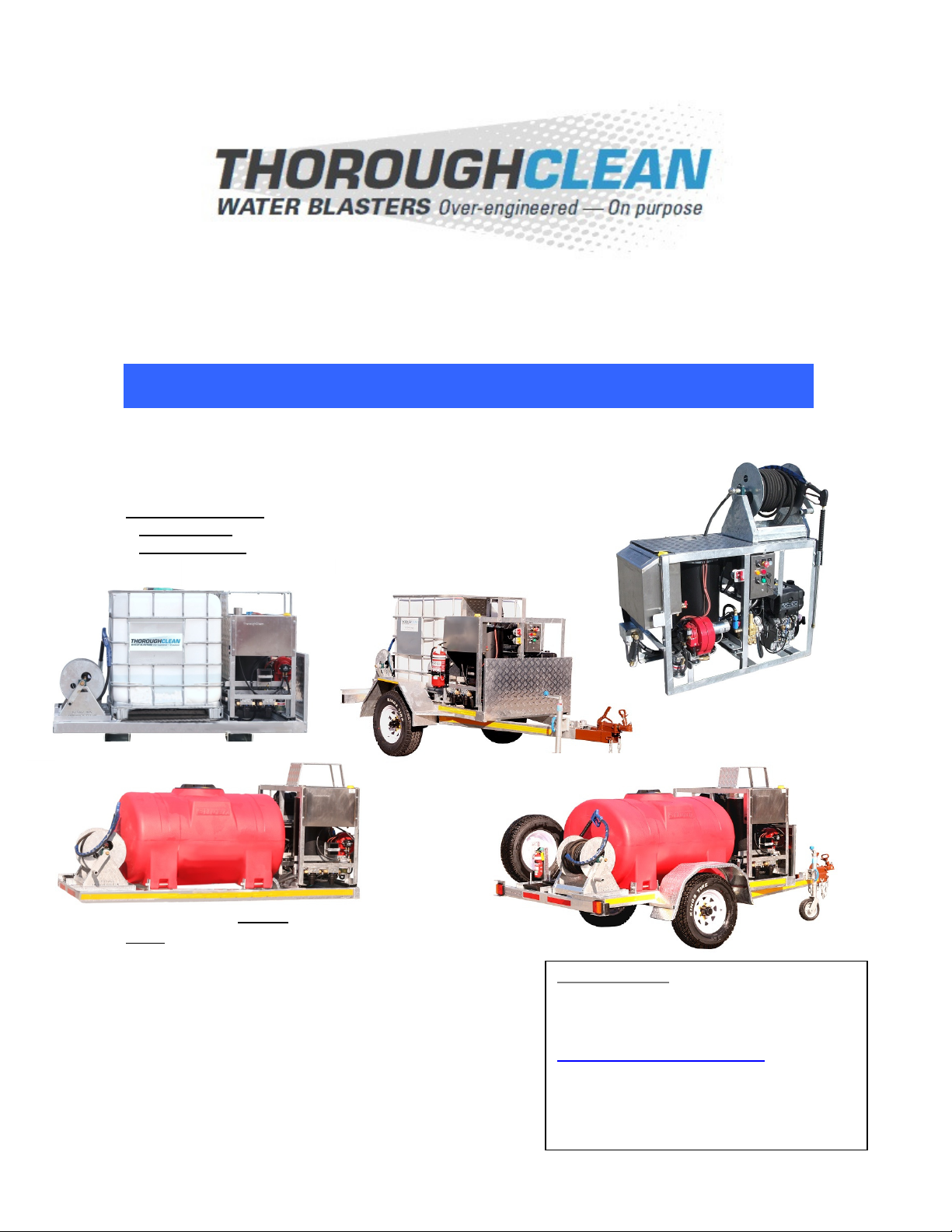
Congratulations on purchasing one of Australia’s
Toughest high pressure water blasters.
Superior Cleaning – designed to last!
OPERATORS MANUAL
for
10 hp KOHLER DIESEL DRIVEN HOT WATER
PRESSURE CLEANERS
Apply to MODELS:
Skid-Mounts: D10M-36H, D10M-36H-BB, D10M-36H-BBO
Trailer Mounts: D10M-36H-T, D10M-36H-TO, D10M-36H-TD
Index:
Page:
2 Technical data / Specifications
3 Installation & Start-up
4 Operating Tips, Shutting do n, Regular Checks
6/7 Maintenance Schedule
8/9 Trouble Shooting Guide
10 What can cause expensive damage to your machine
11 WARNINGS & SAFETY INSTRUCTIONS
12 MEDIC ALERT Information
13/14 Warranties
15 Terms & Conditions of Sale
16 Pump info, by-pass valve info, electrical plan
Manufactured by
:
ThoroughClean Water Blasters
12 Ashburn Road, Bundamba,
QLD 4304, Australia
Ph: +61 (0) 7 5467 2025
www.thoroughclean.com.au
Model & Serial: ………………………….
Date of Purchase: ………………..……..
Purchased from: ……...………………...

2
D10M-36H D10M-36H-BB
D10M-36H-BBO
‘O’ = Oval tank
D10M-36H-T
D10M-36H-TO
‘O’ = Oval tank
D10M-36H-TD
‘D’ = Double Axle
Build Spec Mine Mine Mine Mine
Boiler & Temp Diesel - 70ºC.
21 lit. fuel tank
Diesel - 70ºC.
21 lit. fuel tank
Diesel - 70ºC.
21 lit. fuel tank
Diesel - 70ºC.
21 lit. fuel tank
Frame Type Skid Skid with 1000 litre
tank
Trailer with 1000
litre tank
Trailer with 2000
litre tank
Engine KOHL R 10.3 hp KOHL R 10.3 hp KOHL R 10.3 hp KOHL R 10.3 hp
Model KD440 – 1 Cylinder
Air cooled, 442 cc
KD440 – 1 Cylinder
Air cooled, 442 cc
KD440 – 1 Cylinder
Air cooled, 442 cc
KD440 – 1 Cylinder
Air cooled, 442 cc
Start lectric + recoil lectric + recoil lectric + recoil lectric + recoil
Gearbox 2:1 reduction 2:1 reduction 2:1 reduction 2:1 reduction
Battery • • • •
Battery Box • • •
Ne HAWK Pump
Model NPM1525R NPM1525R NPM1525R NPM1525R
Old HAWK pump
model HC456 HC456 HC456 HC456
Max Pressure &
Flo 3625 psi 15 lpm 3625 psi 15 lpm 3625 psi 15 lpm 3625 psi 15 lpm
Set-up / de-rated
pressure & flo 3000 psi 15 lpm 3000 psi 15 lpm 3000 psi 15 lpm 3000 psi 15 lpm
Nozzle size at set-
up pressure #15045 #15045 #15045 #15045
Pump Speed RPM 1450 1450 1450 1450
Hour Meter • • • •
Engine-Pump
vibe-mounted • • • •
Slave Oil Tank to
pump • •
•
•
S/steel Water
Break Tank • (if required)
Lo ater engine
shut-do n
• (if required) •
•
•
Soft-acting By-
pass Valve • •
•
•
Thermoshield
Protection •
Built-in Reel • (Optional
without)
•
•
•
Hose length 30m 30m
30m
30m
Water Tank 1000 lit. IBC
1000 lit. Poly
1000 lit. IBC
1000 lit. Poly
2000 lit. IBC
2000 lit. Poly
Ind. Water Filter • • (double)
• (double)
• (double)
Gun & 900 mm
s/steel lance • •
•
•
Weight: 335 kg ~400 kg (tbc) ~600kg / ~650kg ~1,100 kg (tbc)
Size (L x W x H)
cm 133 x 71 x 150 224 x 122 x 140
274 x 122 x 110
3.6 x 1.85 x 1.8
4.1 x 1.85 x 1.5 TBC
Mine Spec
Features As Specified As Specified As Specified As Specified
3
Read WARNINGS & SAFETY INSTRUCTIONS before operating machine
INSTALLATION
•Inspect shipment for damages during transit and unpack
WARNING – PLEASE READ SAFETY INSTRUCTIONS FIRST!
•For Skid Mounted machines with no on-board water tank: Connection supply hose to water
supply:
- Important: Use hose with minimum 20 mm inside diameter
- Required pressurised water supply (not gravity) with minimum of 10 PSI and ~20%
more flow that pump flow rate (litres per minute)
- Turn on the water supply (open tap fully). Water will fill the break tank if fitted
For Skid-mounted units with water tanks and Trailer-mounted units – ensure tank has
enough water and the water level is at least above the low level float switch otherwise the
engine won’t start
•Unroll the hose fully ensuring there are no kinks in it
•Trigger gun to expel any air in the system
LAST CHECKS & START:
•Check all hoses are connected and check for damage or water leaks
•Check diesel fuel levels in both engine and Boiler fuel tank
•Check oil level in the pump. The oil sight glass should be HALF full – not more! If oil need
to be topped up, use SAE10W40 or SAE 15W40 or SAE30 and top up at the Slave Oil
Tank if fitted, otherwise on the pump itself.
•Ensure water supply tap (on portable machines) or tank ball valves (on skid mounts and
trailers -if fitted between tank and water filters) are wide open
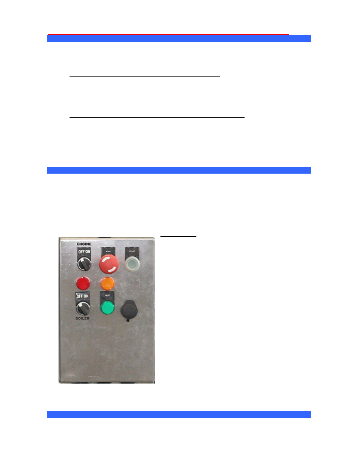
Control Box:
•Ensure that the Emergency Stop button is not
engaged
•Switch on by turning the ENGINE ON/OFF
switch to the ON position or press the GREEN
START button. The machine will fire up, start
pumping and the RED & ORANGE indicator light
will be off.
•The engine is now running, pump is pumping
and water is running in by-pass.
•Pull the trigger on the gun by pointing the lance
in a safe direction.
•When the trigger is released, the pump is still
pumping and water is in by-pass.
TO ENGAGE HOT WATER:
•Turn BOILER ON/OFF switch to ON. The
GREEN Indicator Light will be lit.
•Boiler will fire up and hot water will start to flow
after a few seconds of water blasting.
•The water temperature is pre-set and can not/should not be changed. 99% of fates and oils
melt below 70 degrees Celsius and by keeping water temperature to 70 degrees allows a
higher flow rate to be heated, saving on fuel, longer life from coil and other components.
FAULT INDICATOR LIGHTS:

4
•For units fitted with control boxes with indicator lights: The RED light is an engine fault
indicator light – check engine oil (low pressure) and check that engine isolator switch is not
engaged.
•The ORANGE light is a water fault indicator light: Check water level or water supply when
lit.
REMEMBER: Check Oil Levels DAILY!
NOTE:
•During the first 10 to 12 hours of operation, manufacturing debris like SWARF /
LOCTITE may come through the machine and cause blockages of the high pressure jet.
Switch the machine off, trigger the gun to release stored pressure, remove nozzle and
clean if this occurs.
•Do not crank the engine excessively – no more than 10 – 20 seconds at a time. Allow 2
minutes for starter motor to cool down.
•Engine REVS is locked! Do not unlock or change as this will void your warranty.
Engine revs has been set so engine is running at peak engine torque curve at
comfortable revs – set to the power requirement for the pump, pressure and flow.
DO NOT ALTER!
OPERATING/CLEANING TIPS:
1. Using a Fan Jet, first blast off heavy soil or dirt build-up. The unit comes standard with a 15
degree nozzle correctly sized for the pressure and flow for your machine. Always use the
same size nozzle (NEW) to test the machine for performance
2. Apply detergent to partially cleaned surface using low pressure. (Apply detergent by
spraying from bottom up to avoid streaking - using a dual-lance and detergent assembly.)
Allow to soak for a few minutes.
3. Blast off dirt using high pressure and a 'bottom - up' approach.
4. Lastly, rinse off thoroughly with 'top down' approach.
SHUTTING DOWN:
IMPORTANT – ALWAYS turn boiler off first (by turning the Boiler ON/OFF switch to the ‘OFF’
position) and run cold water through the system by blasting with cold water for 3 – 5 minutes before
shutting down!
•Turn the ON/OFF switch to OFF
•Turn off water supply and disconnect from water supply (Portable skid units only)
•Squeeze gun several times to release any stored pressure
•Lay out high pressure hose straight and then reel back up onto reel (if fitted with reel)
•Lock reel into place using the barrel bolt (only on Trailers and Skid-mount units)
REGULAR CHECKS:
•Check all oil levels :
oKOHLER engine oil level – check dip-stick. Use manufacturer’s recommendations.
oGearbox oil level (sight glass should be half) SAE80W90 Gearbox oil.
oPump oil level (sight glass should be half full) SAE 15W40 / SAE 10W/40 SAE 30
•Water Supply - Low water supply can cause cavitation and/or pump running dry casing
expensive pump failure. Always check to ensure supply is:
oUninterrupted
oPressure is good (10 PSI / 30 LPM)
oThere are no kinks in supply hose
oFittings are in good condition and not leaking
•Worn Jets -System will function okay, but with oversized, worn jets, the pressure will be
much lower and cleaning ability reduced. Always use new jets to check operation efficiency

5
•Operating Pressure - Check operating pressure to see if it within 10% of units specified
operating pressure. If pressure drops over time it may indicate general wear and tear and a
service is recommended.
•Air Leaks - Especially in suction to pump hoses. Repair immediately if found. Check for
cuts & abrasions
•Lance & Gun assemblies - Check for damage and leaks
•Filters - Check to ensure filters are clean, filter heads/tops are not cracked, seals are not
worn and sealed air tight and mesh tube is unblocked
•Motor Speed - Check unit if motor speed is too low. If motor makes a humming sound,
switch off immediately. Do not use extension cords on these units – plug straight into wall
socket!
•SAFETY Ensure safety protective gear is used and in good state of repair. Ensure Safety
MEDIC ALERT Card is handy.
•Prolonged by-pass - Leaving the unit in prolonged by-pass (machine is switched on but
trigger is not depressed) can cause excess wear & tear due to water over-heating which
damages seals. Portable units have a safety mechanisms built in to prevent damage:
oAutomatic dumping of hot water when water temp rises above 63 deg C.
•Worn By-Pass Valves - Soft-Acting By-Pass valves should NOT store high pressure water
in hose down-stream between by-pass valve and high pressure gun.
•Water Leaks - Excessive hammering can cause damage. Fix leaks when they occur
•Water Condition - Ensure water source is clean (potable water). Not recycled water or
bore water which can damage pumps.
•Tyre Pressure – Trailer mounted units only
•Mechanical Brake System – Check all bolts and nuts – tighten if neccesary
Remember to check filters regularly and clean under running water.
The correct procedure for replacing the filter mesh in the small black filters (vs the large grey
filters) is to first put the mesh into the cup after rinsing under running water and then screw it
back onto the filter head. This is the opposite of replacing the filter mesh in the large filters.
Correct procedure of replacing LARGE filter
cartridges on large grey filters:
•Always put the filter mesh tube into the
black ‘head’ first (the part mounted on
the frame) ensuring it is square and tight.
•Now screw on the grey cup part of the filter.
Doing it the opposite way may result in a crushing
of the filter mesh!

6
MAINTENANCE SCHEDULE:
This maintenance schedule does not include the Engine Maintenance Schedule. Please refer to
KOHLER Operators Manual or the HONDA website.
ACTION REQUIRED DAILY 50 HRS 250 HRS 500 HRS ANNUAL
1. Replace high pressure nozzle/jet As
required
YES YES YES
2 Check Water Filters – Clean or Replace if
damaged YES YES YES YES YES
3 Inspect for leaks and repair all HP Accessories
like gun, hose, s ivel, hose reel s ivel, nozzle YES YES YES YES YES
4 Inspect all electrical cabling for damage or
ear – repair by qualified electrician YES YES YES YES YES
5 Check High Pressure S itch & Flo S itch
and replace if faulty YES YES YES YES
6 Check Oil level in Pump (sight glass half full) YES YES YES YES YES
7 CHANGE pump oil – SAE 15W40 / SAE 30
YES YES YES YES
8 Check Oil level in Gearbox (sight glass half
full) and top up ith SAE 80W90 Gearbox oil
YES YES YES YES YES
9 Service transmission, change oil – SAE 80W90 YES YES YES
10 Strip and Refurbish pump:
- Replace Plunger Rod Oil Seals (3/pump)
- Replace Brass Valves (6/pump)
- Replace various seals (3/pump)
- Replace Ceramic Piston Plungers if
cracked or orn (3/pump)
Only if
required
11 Check By-Pass valve function test - re-kit or
replace if required YES YES YES
12 Function test all Safety Shutdo ns & By-Pass
timed shut-do n YES YES YES
13 Check engine sub-frame vibe mounts
YES YES YES
14 Check Boiler electrode gap – set to 3-5 mm YES YES YES YES
15 CONTROL PANEL – Have an Authorised
Electrician Fully Function Test - Repair or
Replace all Electrical Components.
As required or
annually
16 Replace boiler tank fuel filter element YES YES YES
TRAILERS
17 Re-tighten all nuts & bolts on spring
suspension, to -bar hitch, mechanical brakes.
Check tension on mechanical brake cable.
YES YES YES YES
18 Check Tyre Pressure – inflate if necessary Daily Check
MAINTENANCE TIPS:
USE THE FOLLOWING GUIDE WHEN CONSIDERING MAINTENANCE:
Always test your machine using a new high pressure nozzle - correctly sized for set-up pressure
and flow.
Before you start pulling pumps apart, do obvious checks first:
•Worn /blocked Jets
•Air Leaks
•Engine Speed (Not too low)

7
•Power Supply (Not too low when using long leads on 240 Volt units)
•Suction Filters (Blocked?)
•Water supply volume (Not too low)
As a guide in normal use, consider the following:
- After replacing 10 x high pressure Stainless Steel jets/nozzles, it is time to replace the
seals on the pump using a Seal Kit.
- At the same time, also replace the seals on the By-Pass Valve using a By-Pass kit, or if
economically viable, replace by-pass valve.
- By-Pass Valves will take 3-5 rebuilds before body wear becomes too much and
replacement is needed.
- Do a whole pump changeover at 1,000 – 1,200 hours. (Con Rods, Big Ends & Crankshaft)
- Pistols, swivels & H.P. Hoses are usually uneconomical to repair. Replace as necessary.

8
TROUBLE SHOOTING GUIDE
PROBLEM POSSIBLE CAUSE REMEDY COMMENT
MACHINE WILL
NOT START
Power not plugged in and switched
on
Plug into appropriate outlet and
switch on at the wall, then at the
machine
If lectrical
No Fuel Check Fuel. Re-fill fuel tank. If Petrol or Diesel
No Fuel Open fuel tank ball valve or fuel
solenoid tap
If Petrol or Diesel
No or low water supply Check water supply If fitted with break tank and
auto shut-down
Float switch sticking Check float switch in water tank If fitted
mergency-Stop engaged Disengage If fitted
Battery Isolator switch engaged Disengage If fitted
Starter Isolator Switch engaged Disengage If fitted
Pump oil level too low Top up with SA 15W40 or SA 30 If fitted with low level
switch
Pump oil over temp Allow to cool down If fitted with oil over temp
switch
Boiler over temp Allow to cool down If fitted with over temp
switch
Timed by-pass shutdown First switch off and then on again Some electrical units
Check if there is water in the suction
line
Check if the gun is open
Check if nozzle is not blocked
THE PUMP
RUNS BUT DOES
NOT PRODUCE
NOISE OR
PRESSURE
The pump is not primed and is
running dry
Check that the valves are not
blocked
Cavitation or air in the system Check suction hose. Increase
diameter size for bigger supply
Damaged ceramic plunger Replace Plunger
SHORT
PLUNGER SEAL
LIFE
xcessive pressure and/or temp in
the pumped water
Check the temperature and pressure
of inlet water
Problems with pump-motor
connection
Check status of drive shaft keys,
flexible coupling or pulley
The oil has not been changed
regularly
Change oil as instructed in the
maintenance schedule
SHORT BEARING
LIFE
xcessive pressure of pumped
water
Check the pressure
Sucking air Check Suction for Air Leaks
Valves Sticking Remove – Clean – Replace Check Water Quality
Seat in Unloader Valve Worn/ By-
Passing Water
Remove – Fit BPV Service Kit Or
xchange Valve
Probably Indicate Service
Required
HP Jet Wrong Size – Worn Out Check – Replace
Worn Piston Plunger H.P. Seals Check – Replace Check Pistons for Cracks
Pressure control valve not set right Calibrate valve. Check seal seat
Low speed/rotation Check motor revs and drive
MACHINE
RUNNING OKAY,
BUT NOT
REACHING
SPECIFIED
PRESSURE
Insufficient Water Supply Check Available Water Supply. Clean
Filters in Suction Line. Increase
supply hose size
Valves Worn/Sticking Remove – Clean – Replace Check Water Quality
Blockages/Debris in By-Pass Valve Remove – Clean – Replace Check Filters for damage
Pump Sucking Air Seal Suction
FLUCTUATING
PRESSURE
Jet too small Check correct size and replace

9
Worn Piston HP Seals Remove – Clean – Replace Service Required
Fair Wear / Tear? Check – Replace HP Jet Check Recent
Activity/Usage
Suction/Delivery HP Outlet Valves
Worn
Check – Replace Therefore Check suction
Filters
Unloader Valve Worn Replace as required
Piston Seals Worn Replace as required Check Big nds for Piston
Slap
Piston Cracked Replace as required Check Big nds for Piston
Slap
”O” Rings Failed/Leaking Replace as required
”Big nd” Worn Replace as required
PSI LOW AFTER
PERIOD OF USE
Drive Belts Loose (if belt driven) Check / Tighten
Air in Suction / Pump Cavitating Identify Air Ingress/Seal
Problem with pump-motor
connection
Check gearbox or coupling
Broken or Weak Suction Valve
Spring
Check – Replace – As Set
Valves Clogged/Sticking Check – Replace – As Set
Worn Main Crankshaft Bearings Probably Uneconomical to
Repair
PUMP VERY
“NOISY”
Inlet Water Temp over 75 deg
Celsius
Reduce inlet Water Temp Left in By-Pass for
excessively long periods?
Piston to Crankcase Oil Seals Worn Check and Replace Look for Oil under Pump –
Low Pump Oil
Condensation from High Ambient
Humidity
Replace oil more frequently
Piston Seals Worn/Cracked Piston Check – Replace
OIL IN PUMP
EMULSIFIED/
CONTAMINATED
BY WATER
( ater in the
oil) Water Blasted into Pump via
Breather Cap during Cleaning
xercise Care
H.P. Piston Seals Worn or Check and Replace Seal Pack
Worn Plunger Replace Plunger
Worn Plunger Stop Seal Replace Seal
WATER
DRIPPING FROM
UNDER PUMP
(Bet een
crankcase and
manifold
housing)
“O” Rings in Plunger Retaining Bolt
Worn
Check and Replace
OIL DRIPPING
FROM UNDER
PUMP
(Bet een
crankcase and
manifold
housing)
Piston to Crankcase (Plunger Shaft)
Oil Seals Worn
Check and Replace Check Pump for Low Oil
therefore “Big nd”
Damage
Accumulator Failed Check – Replace
Worn Seals (Wet end seals) Replace if worn
Worn Plunger Seals Replace if worn
In/Out Pump Valves Worn Check – Replace
Valves full of scale/dirt Clean or replace
Pistons Cracked Check – Replace
Low Water Supply Increase supply
EXCESSIVE
VIBRATION/
PULSATIONS IN
HP DELIVERY
LINE
Gudgeon Pin in Conrod Stretched Check – Replace
WATER FILTER
MESH IS
CRUSHED WHEN
REPLACED
Incorrect replacement procedure
on Grey NY126 Water Filters with
Blue or Red mesh tube
First insert mesh tube tightly into
the fixed black head of filter
assembly and then screw on grey
cover /cup tightly.
For small black filters, first
insert mesh tube into cover
/cup and then screw onto
fixed part.

10
HOW TO CAUSE EXPENSIVE DAMAGE TO YOUR MACHINE
WHAT WAS DONE WRONG: WHAT WAS THE RESULT OF THIS ACTION:
Cracked and burnt high pressure seals in pump. Machine was allowed to run dry
(without water supply) No. 1 piston cracked due to thermal shock.
Mechanical damages to EVERYTHING:
- Pistol, HP hose, pump valves, pistons
- Crankshaft bearing failure
- Pressure gauge failure
- By-pass valve excessive wear & tear
- Frequent O-rings blow outs
Unit was run on low volume
water supply and allowed to
cavitate
- Brass heads deformed
Over adjust by-pass valve to try
and increase PSI
Dump pressure was too high. Hydraulic hammer to system every
time trigger is closed. PSI was increased 5-fold normal working
pressure.
xcessive wear & tear on pistons / valves / seals / HP jets.
xcessive blocking of filters caused by bore or recycled water with
high salt / mineral content. Pump clogged up with debris.
In-Line filter was removed
because “It kept blocking up!”
Remember: Spec requirement says: “Potable ater”
Over-revved engine for more PSI ngine & Pump premature wear & tear. (Most increased PSI
pressure is lost through by-pass valve and only small increase in
pressure is achieved doing this!) Lost of waster horse power!
When orifice is reduced, the PSI will rise and then by-pass valve will
dump (thinking the pistol is shut). Most extra PSI will be dumped and
only a slight increase in PSI will be achieved.
COMMON MISTAKE: Put a
smaller HP Jet onto lance for
higher pressure.
ngine, By-pass valve & Pump premature wear & tear.
Using Contaminated Fuel (“Had
to remove fuel filter to keep
engine running!”)
xcess Fuel-system clean-outs required. If excessive corrosion in
carburetor or injectors is detected after the 2nd or 3rd in-line fuel
filter replacement, then this should ring alarm bells.
Park machine where debris
blows all over it. Reverse
bulldozer over it.
Our machines are rugged and strong – but not battle tanks!
Hire units long-terms and fluid
levels are not checked.
Con-rod through the crank case!
Modify 240 Volt electric unit to
override thermal overload on
motor.
Stop-Start capacitors melted.
Used 100m extension lead and a
5 Kva Gen-Set.
A 10% low current is equivalent to a 50% over-load.
Our 3 hp 240 Volt motors require 8 Kva Gen-Set minimum!
Run trucks, fork-lifts, tracked
excavation equipment over
hoses and lance
assemblies/pressure guns.
Needs replacing of damaged parts

11
Read WARNINGS & SAFETY INSTRUCTIONS before operating machine
HIGH PESSURE, HIGH VELOCITY HOT WATER IS DANGEROUS!
GENERAL PRESSURE CLEANER WARNINGS AND SAFETY PRECAUTIONS
•Caution – HOT WATER. Danger of severe burns. Proceed with caution!
•When shutting down, always turn off machine, turn off water at the source and trigger the
gun pointing the lance in a safe direction to release any in-line stored pressure - before
disconnecting hoses or working on machine.
•Never aim high pressure water jet at anyone, at animals or at fragile items - injury or
damage could result.
•Always be aware of overhead cables, run-off water, slippery surfaces and by-
standers!
•Never allow untrained adults or minors use of the equipment.
•Never use the machine if there are any leaks on the high pressure delivery side of the
pump.
•Read and observe the manufacturer's instructions if chemicals are being used.
•The “recoil” on larger machines is positive - lean forwards and brace yourself to take it up!!!
•NEVER HIGH PRESSURE BLAST THE FOLLOWING: any electrical components, motors
/ switchgear or electrical boxes as injury or death may result.
•Never water blast any fuel caps or oil caps and water can get into breather holes and
contaminate fuel or water. Never blast water directly into seals / bearings on shafts where
water penetration would be detrimental.
•NEVER WATER BLAST: fragile items / surfaces that may be damaged by high velocity
water. Always carefully test on a small area first.
•ALWAYS WEAR PROTECTIVE GEAR (PPE) i.e. Head, face, eye protection, wet weather
gear, boots and gloves - which is particularly important where hot water or aggressive
chemicals are being used or where whet sandblasting is used.
•Keep hands, feet and hair away from all moving parts.
•Never leave machine running unattended.
•EXTREME DANGER - never adjust engine speed (RPM) or safety by-pass valve in an
attempt to increase pressure!
•Barricade off immediate work area - restrict access - erect hazard warning signs.
•Never use high pressure water cleaner without protective canvas sheaths on operator end
of high pressure hose as a high pressure leak can injure operator.
•In commercial / industrial sites class 'b' units (pressures over 5,000 PSI) should have
additional operators allocated as safety observer / machine minder subject to work
conditions / environment. This is a responsibility of the 'site occupier' to determine.
•If two / three operators are working they should be physically separated by partitions /
barriers.
•Prior to high pressure water blasting, check location’s level of emergency /first aid.
•All machines are fitted with MEDIC ALERT tags. If a high pressure water injury occurs
which need medical attention, pull off machine and give it to the medical practitioner to read

12
WARNINGS & SAFETY PRECAUTIONS SPECIFIC TO THIS MACHINE:
•This machine produces HOT WATER at high pressure – take extreme caution!
•Severe burns and injury can result. Beware of hot exhaust air, hot chimney and a hot
lance!
•Use only Clean / Fresh POTABLE Water - NOT Mine recycled water.
•Always be conscious of High Velocity Hot Water from this machine which can cause
serious injury and burns
•Run up and test all safety shutdowns regularly i.e. Monthly.
•NEVER attempt to modify levels of performance by:
o
Adjusting By-Pass Valve to increase P.S.I.
oUse Under-sized High Pressure Nozzles.
•EXTREME DANGER! Use Specified and approved Personal Protection Equipment (PPE)
for High Pressure Cleaners. This is a High Performance High Pressure Cleaner. At a
Minimum wear:
oOveralls /boots /thick heavy gloves /full face protection.
oAdditional equipment as instructed by site personnel or Australian regulations for
high pressure water jetting
An injury by high pressure water jets can be serious!
In the event of any waterjet injury:
•Seek medical attention immediately – do not delay
•Inform the doctor of the cause of the injury
•Show the doctor the MEDIC ALERT information in this document or by pulling the safety
tag off the machine and taking it with you to the doctor
•Tell the doctor what type of project/task was being performed at the time of the injury
making special note of any chemicals that were used and the quality of the water
MEDIC ALERT INFORMATION:
ALWAYS ENSURE MACHINE IS FITTED WITH A REMOVEABLE MEDICAL ALERT / WARNING
TAG AND TAKE THIS TO A MEDICAL PRACTITIONER WHEN A HIGH PRESSURE WATER
INJURY OCCURS.
MEDIC ALERT INFORMATION:
This patient may be suffering from a water-jet injury. Evaluation and management should parallel
that of a gunshot injury. The external manifestations of the injury cannot be used to predict the
extent of internal damage. Initial management should include stabilization and a thorough
neurovascular examination. X-rays can be used to assess subcutaneous air and foreign bodies
distant from the site of injury. Injuries to the extremities can involve extensive nerve, muscle, vessel
damage, as well as cause a distal compartment syndrome. Injuries to the torso can involve internal
organ damage. Surgical consultation should be obtained.
Aggressive irrigation and debridement is recommended. Surgical decompression and exploration
may also be necessary. Angiographic studies are recommended pre-operatively if arterial injury is
suspected. Bandages with a hygroscopic solution (MgSO4) and hyperbaric oxygen treatment have
been used as adjunctive therapy to decrease pain, edema and subcutaneous emphysema. Unusual
infections with uncommon organisms in immuno-compromised patients have been seen; the source
of the water is important in deciding on initial, empiric antibiotic treatment and broad-spectrum
intravenous antibiotics should be administered. Cultures should be obtained.

13
THOROUGHCLEAN LIMITED WARRANTY
In order to take advantage of the ThoroughClean limited warranty, you must have maintenance
performed according to the schedule (contained in the relevant owners manual supplied with this
product), by an authorised ThoroughClean dealer or ThoroughClean service technician.
You are free to have your ThoroughClean product serviced by any suitably qualified mechanic or
electrical (depending on the requirement mechanical or electrical) and this will not affect your
statutory warranties, however, failure by the owner to have the recommended servicing carried out
by an authorised ThoroughClean dealer means that you cannot take advantage of the
ThoroughClean limited warranty.
In order to ensure your safety, we strongly recommend that you only use an authorised
ThoroughClean dealer for servicing. Only authorised ThoroughClean Dealers have access to all of
the special tools, technical information, parts and training required to maintain your ThoroughClean
product in peak operating condition.
ThoroughClean warrants each new ThoroughClean Pressure Cleaner to be free from defects in
material and workmanship under normal domestic and Industrial use and service for the period
specified below, conditional to the limitations and exclusions printed on this page. This warranty
applies only to new ThoroughClean pressure cleaners distributed in Australia by us and by our
authorised ThoroughClean dealers.
LIMITED WARRANTY
Our goods come with guarantees that cannot be excluded under the Australian Consumer Law.
You are entitled to a replacement or refund for a major failure and compensation for any other
reasonably foreseeable loss or damage. You are also entitled to have the goods repaired or
replaced if goods fail to be of acceptable quality and the failure does not amount to a major failure.
The benefits to the consumer under this warranty are in addition to other rights and remedies of the
consumer under a law in relation to the goods sold under warranty.
Warranty Period/s:
- 1 year ThoroughClean Manufacturer's Warranty on Build (Defects in material and
workmanship)
- 5 year ThoroughClean Manufacturer's Warranty on Galvanized Frames and Galvanized
Reel (Defects against rust & welding cracks)
- 12 months ThoroughClean Warranty on Pressure Pump (Note: Maintenance is not
warranty. Excludes service and consumables required at scheduled maintenance intervals)
- 2-year Manufacturer's Warranty on Electric Motors
- 3-year HONDA GX Warranty on HONDA engines. Please see
www.hondapowerequipment.com.au for details
- 3-year or 2000 hours Manufacturer's Warranty on KOHLER engines (whichever comes first)
(See KOHLER Owners Manual and website for details)
Responsibility of the Consumer under this Limited Warranty:
- Only clean, potable water should be used through our pressure cleaners with a flow rate at
least 15% more than the pump requirements (e.g. an 18 LPM pump requires at minimum a
water supply of 21 LPM to prevent pump cavitation)
- Strict adherence to the maintenance daily checks and schedule with proof of scheduled
maintenance service required by an authorised agent or qualified mechanic and/or
electrician.
- Maintenance Services is not covered under warranty. (Warranty excludes normal
maintenance and consumables like oil, nozzles, swivels, filter mesh, HP hose, guns, by-
pass valves)
- It is the consumer's responsibility to deliver the machine in question to our service premises
or to the premises of our appointed agent at the consumer's expense for replacement or
repair as applicable.

14
Claim Procedure:
- Contact ThoroughClean by phone or e-mail informing us of your pressure cleaner's
problem or defect.
- Once the extent of the claim has been assessed, we retain the right to compensate the
consumer for such defect, or repair (pars & labour), or replace the machine under warranty.
- All warranties will be carried out by ThoroughClean authorised staff or appointed agents at
a premises to be determined by the Manufacturer.
- It is the responsibility (and cost) of ThoroughClean or our appointed agent to return the
machine to be repaired or replaced under warranty to the consumer – this is valid for
Australian territories only.
- Where the specific warranty component (e.g. engine) is a Manufacturer's warranty other
than ThoroughClean (e.g. HONDA), the consumer can either contact ThoroughClean or the
applicable Manufacturer for repairs where such warranty was registered with that
Manufacturer at purchase.
- Warranty calls will only be carried out during normal working hours and only by our
representatives and not via client's choice of repairer. We will not accept back charges for
any work not carried out by our representatives, or accept any charges due to equipment
being un-operational for any reason even during its warranty period.
THIS WARRANTY WILL NOT APPLY TO:
- Any part/component that has been subject to misuse, negligence, accidental damage,
improper or inadequate maintenance or improper storage.
- Any part that has been subject to misuse, negligence, accidental damage, improper or
inadequate maintenance, or improper storage.
- Repair rendered necessary or arising from the use of parts or components other than
approved by the manufacturer in writing.
- Normal maintenance, replacements of service and consumable items including but no
limited to nozzles, seals, oil, guns, swivels, filters, by-pass valves and HP hose.
- Deterioration of any item due to normal use, fair wear and exposure unless due to a defect
in material or workmanship.
- Any work or adjustment performed by persons other than authorized ThoroughClean
service staff or authorized dealers or damage resulting there from.
- Any damage that results from operating methods other than those indicated in the owner's
manual, or use beyond the limitations or specifications as published in the Specification
Sheets of the particular model.
WARRANTY CONTACT INFORMATION:
Tel +61 (0) 7 5467 2025
Fax +61 (07) 5467 2026
service@thoroughclean.com.au
12 Ashburn Road, Bundamba, Queensland
4304, Australia
SERVICE & PART ORDERING
For service and ordering parts, please call 1300 378 872 or 07 5467 2025
Or your nearest ThoroughClean Distributor
We have very knowledgeable, experienced staff to assist you with help and advice.

15
TERMS & CONDITIONS OF SALE:
1. Work for special build machines will not commence unless a 30% deposit has been made
and/or official purchase order has been received.
2. The final configuration and optional extras are to be agreed to before manufacturing
commences. An extra cost for changing a model will apply after manufacturing has started
(if this change leads to extra manufacturing cost or more expensive/extra components) and
be charged as a variation cost.
3. Ownership/title of all equipment remains the property of ThoroughClean until paid for in full.
Warranty will only be available after this time.
4. Warranty is not service. Any calls placed to service equipment will be chargeable to the
client. Earlier replacement of consumable parts than what is required by the maintenance
schedule will be at the cost of the client (excluding of course any repairs/replacement of
parts required under warranty). Please see the LIMITED WARRANTY information
elsewhere in this document.
5. All Rental Spec and Mine Spec model frames will have a hot dip galvanized finish unless
elsewhere agreed to in a proposal offered to the client. Industrial Spec frames will have a
painted finish or galvanized finish – the latter usually at extra cost.
6. Any additional spares, service kits, nozzle kits, etc are excluded, unless otherwise
mentioned in the proposal to the client.
7. Any extra installation and fitting expenses and all electrical or plumbing work required
during installation will be at the cost of the client. It is the responsibility of the client to
provide adequate pressured water supply of potable quality 15% more than the required
flow of the pressure pump specification, and suitable power supply outlet for electrical units
where applicable.
8. No responsibility will be taken for late delivery day due to unforeseen circumstances.
Please regard building times for special builds and machines out of stock as estimates only.
9. Sale of this unit/s is on an FOB Bundamba, QLD basis unless otherwise agreed to in
writing in this proposal and it is the responsibility of the client to insure goods in transit.
10. Our price quoted is valid for 30 days only unless stated otherwise elsewhere in the quote.
11. Where deposits have been paid on special builds, such deposits will in part or in full
become non-refundable once building has started. Should a customer decide to cancel an
order - all labour and a re-stocking and administration fee for components will be charged
to the customer and the balance (if any) repaid to the customer. Any special non-
restockable components will be invoiced to the customer.
12. All prices quoted are excluding GST and freight unless otherwise stated.
13. All prices quoted does not include installation (where applicable) or training unless
otherwise stated.
14. Installation and training service of $90/h available in Brisbane Metro only. Other sites
subject to additional travel cost.
15. IN NO EVENT SHALL THOROUGHCLEAN BE LIABLE FOR ANY INJURY, EXPENSES,
PROFITS, LOSS OR DAMAGE, DIRECT, INCIDENTAL, OR CONSEQUENTIAL, OR ANY
OTHER PECUNIARY LOSS ARISING OUT OF THE USE OR INABILITY TO USE ANY
PRODUCT DESCRIBED IN THIS DOCUMENT.
DISCLAIMER: Although care has been taken to ensure the accuracy, completeness and reliability
of the information provided, technical features may vary due to ongoing improvements and
development. The user of the information agrees that the information is subject to change without
notice.
39
35
36
38
37
34
26
40
41
42
1
29
33
6
10
9
8
13
12
14
20
19 11
43
44
45
48
31
32 23
16
25
30
15
16
17
18
27
46
47
24
3
28
74
2
26
25
23 16
21
22
13
14
11
18
12
5
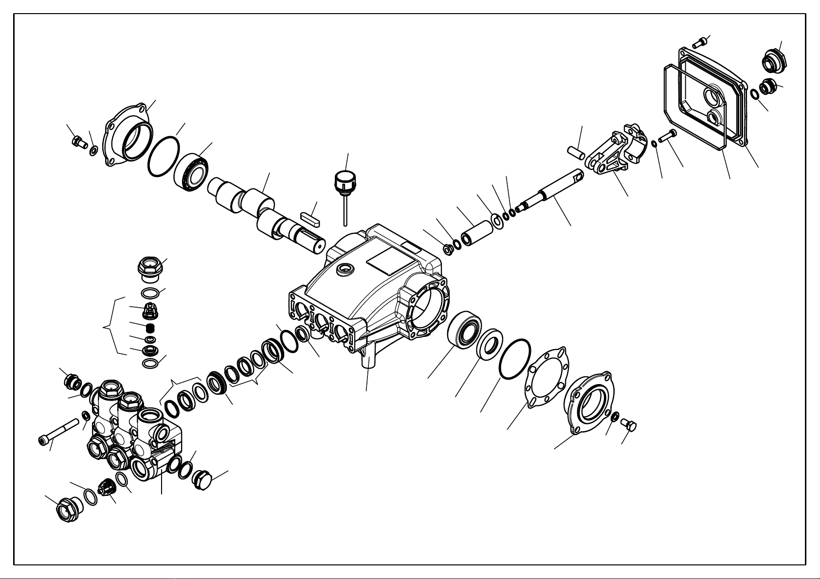
Hawk
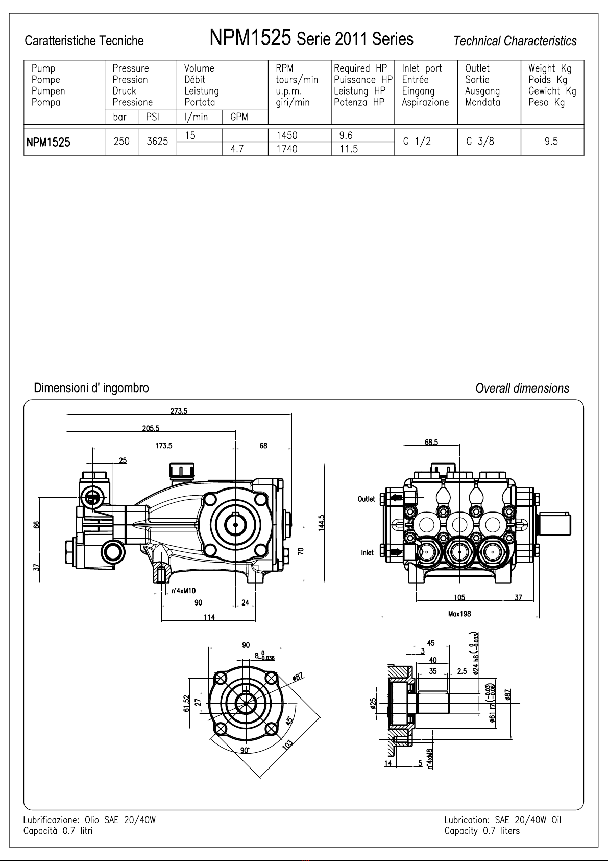
NPM1525 serie 2011
NPM1525 pump 2011 series
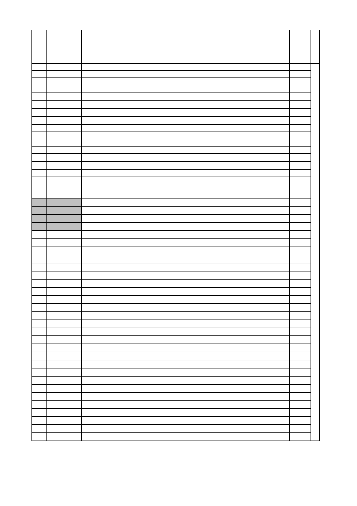
PARTS LIST NPM1525 pump 2011 series
Item Part Number Description
Q.ty
by
Pump
NPM1525R/L
10202.9
5
Crankcase 1
*2 0001.0
3
Plunger oil seal 3
*3 0601.0
7
"O" Ring Ø1.78x31.47 3
*4 1201.3
8
Pressure ring 18mm 3
*5 0002.51 Low pressure "U" seal, dia.18mm 3
*6 0300.16 Intermed. ring 18mm 3
*7 0002.64 High pressure "U" seal, dia.18mm 3
*8 0603.07 Copper washer G1/2 1
*9 1601.2
0
Brass plug G1/2 1
*10 1602.3
4
Manifold housing 1
*11 0601.1
9
"O" Ring Ø2.62x17.13 6
*12 3604.7
0
Valve assembly 6
*13 0601.65 "O" Ring Ø2.62x20.29 6
*14 1601.30 Valve plug 6
15 1801.0
3
Manifold stud bolt M8x65 Dacromet 8
16 1400.01 Washer Ø8,5 16
*17 0603.0
6
Copper washer G3/8 1
*18 1601.1
7
Brass plug G3/8 2
19 1503.18 Valve seat 6
20 1202.00 Valve plate 6
21 0900.30 Valve spring 6
22 0604.05 Valve cage 6
23 1802.03 Hexagonal screw M8x18 8
24 0500.61 Closed bearing housing 1
25 0601.63 "O" Ring Ø1.78x60.05 2
26 0200.06 Roller bearing 33205 2
27 0006.15 Single - ended shaft 1
28 0206.04 Crankshaft key 1
29 1600.02 Oil dip stick 1
30 0001.02 Crankshaft seal 1
31 0301.16 Shim 1
32 0500.60 Bearing housing 1
*33 0302.19 Plunger nut 3
*34 1400.12 Copper spacer Ø 11.2/15x0.5 3
*35 1200.09 Plunger 18mm 3
*36 1400.15 Copper spacer Ø 11.3/24x0.5 3
*37 0601.03 "O" Ring Ø1.78x7.66 3
*38 0009.04 Teflon ring 3
*39 0003.28 Plunger rod 3
*40 0100.01 Connecting rod 3
*41 1502.06 Connecting rod pin 3
*42 1401.02 Spring washer Ø6 6
*43 1801.05 Connecting rod screw M6x25 6
44 0601.88 "O" Ring Ø 2.62x126.67 1
45 0203.59 Crankcase cover 1
46 0601.14 "O" Ring Ø1.78x14 1
47 0700.05 Sight glass, G3/4 1
48 1801.12 Screw M6x16 4
Leuco Spa Pagina 1 03/01/2011
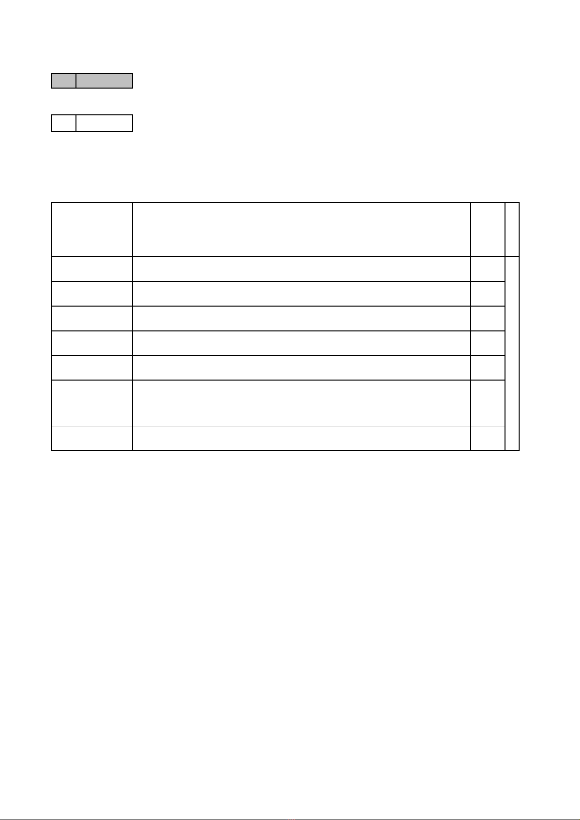
PARTS LIST NPM1525 pump 2011 series
Part available
in kit only
*Part available
in kit also
Part Number and Description Q.ty by
pump
NPM1525R/L
2600.38 Plunger Seals 18 mm 1
2600.37 Complete Seals Packing 18 mm 3
2612.42 Plunger 18 mm 3
2600.08 Complete Valve 6
2608.03 Plunger oil Seals 1
2600.75 Complete Manifold 1
3100.13 Connecting Rod-Plunger Rod Assy 3
33- 34- 35- 36- 37
38
SPARE PARTS KIT
Included Position
3- 5- 7
3- 4- 5- 6- 7
3- 4- 5- 6- 7- 8- 9
10- 11- 12- 13- 14
17- 18
11- 12- 13
2
39- 40- 41- 42- 43
Leuco Spa Pagina 2 03/01/2011
SPECIFICATIONS
Part Number
Maximum Volume
Maximum Discharge
Pressure
Max.Temperature
Port Sizes: Inlet
Bypass
Outlet
Dimensions
Weight
ZK7.0
2.1-2.9 GPM
0-3000 PSI
165°F
3/8-19 BSPP - F
3/8-19 BSPP - F
3/8-19 BSPP - M
7.50 x 3.75 x 3.50 in.
4.5 lb.
ZK7.1
2.9-4.2 GPM
0-3000 PSI
165°F
3/8-19 BSPP - F
3/8-19 BSPP - F
3/8-19 BSPP - M
7.50 x 3.75 x 3.50 in.
4.5 lb.
ZK7.2
4.2-6.6 GPM
0-3000 PSI
165°F
3/8-19 BSPP - F
3/8-19 BSPP - F
3/8-19 BSPP - M
7.50 x 3.75 x 3.50 in.
4.5 lb.
ZK7.3
6.6-10.8 GPM
0-3000 PSI
165°F
3/8-19 BSPP - F
3/8-19 BSPP - F
3/8-19 BSPP - M
7.50 x 3.75 x 3.50 in.
4.5 lb.
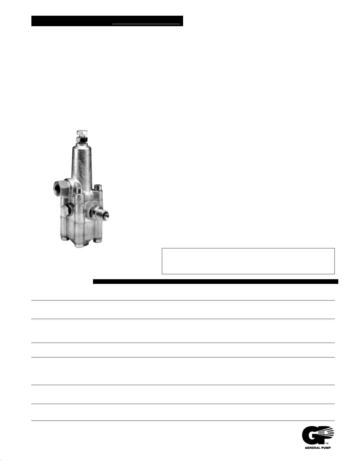
K7 UNLOADER VALVE
K7.0 2.1 - 2.9 GPM @0 - 3000 PSI
K7.1 2.9 - 4.2 GPM @0 - 3000 PSI
K7.2 4.2 - 6.6 GPM @0 - 3000 PSI
K7.3 6.6 - 10.8 GPM @0 - 3000 PSI
Features all stainless and brass internal parts.
New design reduces sensitivity to entrapped air.
No external moving parts or springs.
Unique barb and flow balance design provides
gradual pressure build-up when system is closed.
Eliminates high pressure in all lines while unit is in
bypass mode.
Bypass restrictor eliminates pressure peaks during
bypass.
Unique balanced piston design permits precise
pressure adjustments.
Minimum 5% bypass required for operation.
Simple design for easy maintenance and service.
Adjusting knob is optional.
General Pump recommends using a safety relief device in conjunction with
this unloader valve when installed on a positive displacement pump. General
Pump is not liable and assumes no responsibility for this valve when used in
a customer’s high pressure system.
K7
GENERAL PUMP A member of the Interpump Group
This manual suits for next models
5
Table of contents
Other ThoroughClean Pressure Washer manuals

ThoroughClean
ThoroughClean P6R-17C User manual

ThoroughClean
ThoroughClean E3R-22H User manual

ThoroughClean
ThoroughClean P6i-17C User manual

ThoroughClean
ThoroughClean Trailer User manual

ThoroughClean
ThoroughClean E3R-22C User manual

ThoroughClean
ThoroughClean D10R-30C Trailer User manual

ThoroughClean
ThoroughClean D10i-36C User manual


