THRILL VORTEX F1-PRO Operating instructions

Models / Modelli:
CUBE - VORTEX F1-PRO – VORTEX SBI
Date of First Edition: 05-12-2014
Revisions: 4
Last revision: 26-04-2017
Glassware sanitizing appliance user and maintenance manual
Manuale di uso e manutenzione macchina sanicatore di bicchieri
Manufacturer / Ditta costruttrice:
THRILL INTERNATIONAL S.R.L.

2This document is the property of THRILL INTERNATIONAL and may not be reproduced without the company’s prior consent.
TYPE OF GLASSWARE SANIFICATION
AND CHILLING
SANIFICATION
AND FREEZING
Small glass 1 shot
Time 2 seconds
8 grams
shot
Time 2 + 2 second
16 grams
Medium glass 1 shot
Time 3 seconds
12 grams
2 shot
Time 3 + 2 seconds
20 grams
Large glass 1 shot
Time 3 seconds
12 grams
2 shot
Time 3 + 3 seconds
24 grams
Tankard or jug 1 shot
Time 5 seconds
20 grams
2 shot
Time 5 + 5 seconds
40 grams
DELIVERY TIMES ACCORDING TO TYPE
OF GLASSES SANITIZE AND COOLING

GLASSWARE SANITIZING APPLIANCE
User and maintenance manual
RE V. 4
3
ENGLISH
PAGE INDEX
This document consists of 41 pages.
Revisions made to individual pages are provided in the table below.
REVISIONS TO THE MANUAL
Date of the rst edition of the manual - December 2014
Date of the last revision to the manual - April 2017
Rev. N° Date rev. Change Date or S/N
number
0DECEMBER 2014 First Edition All
1MARCH 2015 Gas cylinder safety instructions added All
2 JULY 2015 Various information added and re-paging All
3 MARCH 2016 Information on Vortex SBI updated All
4APRIL 2017 Info added on CUBE model All
Pag. n° Rev. Pag. n° Rev. Pag. n° Rev Pag. n° Rev Pag. n° Rev Pag. n° Rev
1 4 13 425 437 449 -61 -
2 4 14 426 438 450 -62 -
3 4 15 427 439 451 -63 -
4 4 16 428 440 452 -64 -
5 4 17 429 441 453 -65 -
6 4 18 430 442 -54 -66 -
7419 431 443 -55 -67 -
8 4 20 432 444 -56 -68 -
9 4 21 433 445 -57 -69 -
10 422 434 446 -58 -70 -
11 423 435 447 -59 -71 -
12 424 436 448 -60 -72 -
These user instructions are the translation of the original user instructions written in
italian language.

4This document is the property of THRILL INTERNATIONAL and may not be reproduced without the company’s prior consent.
1. GENERAL INFORMATION ................................................................................................................... 5
1.1. QUICK START................................................................................................................................. 5
1.2. MODELS......................................................................................................................................... 5
2. IDENTIFICATION OF PARTS................................................................................................................ 6
3. SAFETY INSTRUCTIONS...................................................................................................................... 7
3.1. INTENDED USE AND PURPOSE................................................................................................... 7
3.2. SAFETY WARNINGS ..................................................................................................................... 8
3.3. DANGER ....................................................................................................................................... 8
4. APPLIANCE DESCRIPTION AND TECHNICAL SPECIFICATIONS..................................................... 9
4.1. DES CRIP TI ON ................................................................................................................................ 9
4.2. APPLIANCE PARTS ..................................................................................................................... 10
4.3. TECHNICAL SPECIFICATIONS....................................................................................................11
5. INSTALLATION ....................................................................................................................................12
5.1. SET-UP INSTRUCTIONS ..............................................................................................................12
5.2. CONNECTING THE GAS CYCLINDER ....................................................................................... 14
6. OPERATION AND USE ........................................................................................................................15
6.1. COMPATABLE GLASSWARE........................................................................................................15
6.2. OPERATING INSTRUCTIONS .....................................................................................................15
6.3. TROUBLESHOOTING................................................................................................................. 16
7. VORTEX SBI APPLIANCE ................................................................................................................... 16
7.1. APPLIANCE DESCRIPTION......................................................................................................... 16
7.2. COMPONENTS.............................................................................................................................17
7.3. INSTALLATION.............................................................................................................................17
8. CLEANING INSTRUCTIONS .............................................................................................................. 18
9. END OF PRODUCT LIFE AND DISPOSAL INSTRUCTIONS .............................................................19
9.1. END OF PRODUCT LIFE...............................................................................................................19
9.2. DISPOSAL.....................................................................................................................................19
10. WARRANTY CONDITIONS................................................................................................................ 20

GLASSWARE SANITIZING APPLIANCE
User and maintenance manual
RE V. 4
5
ENGLISH
1. GENERAL INFORMATION
1.1. QUICK START
To start the machine carry out the following:
1) Unpack the machine, retaining the packaging for any future shipment;
2) Install the machine on a at surface;
3) Place the CO2 cylinder in a place away from and protected from heat;
4) Connect the CO2 cylinder to the solenoid valve, as described in section 5.2 of this manual
and open the cylinder valve;
5) Connect the charger to the existing outlet on the appliance (see gure at centre of page 13);
6) Connect the charger to a power outlet with a voltage between 100 and 240 Vac and leave
to charge for between 8 and 16 hours;
7) When fully-charged, disconnect the charger from the outlet and then from the appliance
and store it in a dry place;
8) Turn on the machine and run on an empty cycle to clean the machine; please note that
this stage may be accompanied by the emission of certain odours resulting from material
residues from the packaging;
9) At the end of the cycle, turn o the machine using the appropriate switch.
IMPORTANT NOTE: It is essential that you read all parts of this manual fully and thoroughly
before operating the machine.
1.2. MODELS
Power switch for
the Thrill Vortex SBI built-in
model
1) Thrill Vortex F1- Pro 2) Thrill Vortex SBI built-in model

6This document is the property of THRILL INTERNATIONAL and may not be reproduced without the company’s prior consent.
This manual is applicable to both versions, except for the position of the POWER ON switch on
the SBI built-in model (see previous diagrams); the SBI model is described in detail in the second
part of this manual.
2. IDENTIFICATION OF PARTS
Cylinder CO2
connection tube
Sanitizing machine Mains Charger
and power cable
The various parts are connected to each other as illustrated on the following page:
3) Thrill CUBE

GLASSWARE SANITIZING APPLIANCE
User and maintenance manual
RE V. 4
7
ENGLISH
Sanitizing machine
Cooling/Sanitizing
Unit
Rechargeable
internal battery
12Volt
Battery
charger
12V DC
CO2 cylinder
with suction pipe
Solenoid valve
3. SAFETY INSTRUCTIONS
• Please read this instruction manual carefully before attempting to operate the appliance for
the rst time, and comply with all safety instructions;
• The appliance must only be used for the purposes and in the manner described in these
instructions;
• Please keep these instructions for future reference;
• Any appliance sold or passed on to third parties must be accompanied by the instruction
manual;
• The use of all models of the Thrill appliance does not preclude the need to wash and sterilize
glasses, which must be thoroughly cleaned after each use.
3.1. INTENDED USE AND PURPOSE
This appliance, which functions using jets of carbon dioxide, is designed expressly for the
purpose of sanitizing and cooling glasses or glass and plastic containers. It is intended for both
professional and home use. Use of the appliance in small enclosed areas requires the presence
of adequate ventilation in order to prevent the build-up of toxic fumes harmful to human health
(i.e, concentrations above 0.5%).

8This document is the property of THRILL INTERNATIONAL and may not be reproduced without the company’s prior consent.
3.2. SAFETY WARNINGS
Please pay attention to the safety symbols used in this instruction manual, which are as follows:
DANGER! High risk: Failure to observe this warning may result in fatal injury or serious
material damage.
HAZARD WARNING: Medium Risk: Failure to observe this warning may result in injury or serious
material damage.
CAUTION: Low risk: Failure to follow this warning may result in minor injury or material damage.
3.3. DANGERS
The potential dangers associated with the appliance during various stages of its operation and
use are listed below:
- DANGER TO CHILDREN AND THE THOSE WITH DISABILITIES
Children should not be allowed to play with any of the packaging material or protective plastic
bags. Please keep the appliance out of the reach of children and always maintain a watchful
eye when children are in the vicinity of the machine.
The appliance is not suitable for use by children, by adults with limited physical, mental, or
intellectual capacities, or those lacking necessary experience.
Ensure that children do not play with the appliance, knock it over, cause the adapter to fall, or
tamper with the CO2 cylinder.
- POWER SUPPLY
• To avoid the risk of electric shock, protect the appliance from humid and damp conditions,
splashes of water or drops of moisture.
• Do not use the appliance outdoors or near water-lled receptacles, such as sinks.
• Make sure that the support base beneath the unit is dry.
• Do not use the appliance if the power supply unit or power cable are damaged in any way or
if the machine itself has been previously knocked over or dropped.
• To avoid risk, do not modify or make any changes to the product. Do not replace the
connection cable yourself.
• In case of the need for repair, do not attempt such repairs yourself. Only have your appliance
repaired by our service centre or laboratories authorized by Thrill International.
• In the event that liquids penetrate the appliance casing or foreign objects fall into the
appliance, immediately disconnect the plug from the electrical supply.
Have the appliance safety checked before operating it.
The appliance casing, power cable, power adapter, and plug must not be immersed in water
or other liquids.
However, in the event that the appliance falls into water or other liquid, immediately remove
the plug from the electricity supply. Under no circumstances touch or attempt to remove the
appliance until you have done so. Do not attempt to use the appliance until a specialist laboratory
has checked it.
Do not touch the power adapter or cable with wet hands.
Connect the plug to a properly tted and easily accessible power socket, whose voltage
corresponds to the specications provided on the rating plate. The power socket must
remain easily accessible once the appliance has been connected. Make sure that the power
cable is not susceptible to damage from sharp edges or hot spots.

GLASSWARE SANITIZING APPLIANCE
User and maintenance manual
RE V. 4
9
ENGLISH
The appliance is not completely disconnected even after it has been switched o and
therefore to ensure it is completely isolated from the power supply, remove the plug.
When positioning the appliance, ensure the power cable is not kinked or crushed.
To remove the plug from the wall socket, always pull the plug and never the cable.
The socket outlet must be protected by a RCD with IΔn ≤ 30 mA instantaneous trip.
If in doubt, consult a qualied electrical installer.
- HYGIENE
The appliance must be cleaned regularly in order to prevent the growth of bacteria.
Do not place dirty glasses containing liquid residues on the grille.
Avoid the build-up of liquid in the drip tray.
While the sanitizing action combats the build-up of bacteria in glassware, it is not a substitute
for the cleaning and sanitization performed by a dishwasher.
- USE
Never look directly into the jet stream or directly expose it to parts of the body (face, hands,
arms, etc.), in order to avoid the risk of frost burn.
Avoid placing your hands inside the basin during operation or immediately after appliance use.
Before using the appliance, ensure it is completely dry, as the presence of water in the tank
can lead to splashing and potential frostbite; if liquids have accumulated in the drip tray, dry
it thoroughly.
There is a risk that protective treatments and nishes applied to work surfaces may cause the
rubber feet tted to the appliance to corrode or become stuck to the surface; to ensure this
does not occur, place a non-slip base or mat under the machine.
Do not use detergents or acids for cleaning surfaces; only use products specically suitable
for cleaning stainless steel.
Clean all exterior surfaces of the machine by hand; the nozzle, rosette and accompanying
parts can be washed in a dishwasher.
4. APPLIANCE DESCRIPTION AND TECHNICAL SPECIFICATIONS
4.1. DESCRIPTION
The sanitizer appliance is designed to reduce the presence and build-up of bacteria in ready to use
glasses and plastic containers by means of a rapid chilling action using jets of food grade liquid
carbon dioxide (E290). This process not only eliminates most of the pathogens present on the
inner surface and on the edge of the glass or container but also has a cooling or chilling eect, thus
enhancing the taste of the contents. The process consists of blasting the inside of the glass with
a jet of carbon dioxide at 78.5 degrees below zero, which cools both the interior and surface of
the glass. This cooling and sanitization process reduces the presence of principal micro-organisms
considerably, as the following table reporting the analyses carried out by the University of Udine
demonstrates, thus optimizing glass hygiene.

10 This document is the property of THRILL INTERNATIONAL and may not be reproduced without the company’s prior consent.
The carbon dioxide is drawn in a liquid state from a special gas cylinder (available upon request)
and converted into a gaseous state upon vaporization. Please note that under certain atmospheric
conditions dependent upon temperature, humidity and low atmospheric pressure, etc., dry ice
may form on the machine nozzle; this phenomenon, which may last for a few hours, is by no means
abnormal and does not compromise the functioning of the appliance in any way. Any dry ice on the
glass will evaporate within few seconds without leaving any trace.
4.2. APPLIANCE PARTS
The appliance consists of the following parts:
- Glassware sanitizer, as illustrated in the diagram below:
Micro-organism Reduction percentages
Salmonella enteritidis > 88 %
Staphylococcus aureus > 83 %
Escherichia coli > 87 %
Penicillium nalgiovense > 83 %
Listeria innocua > 80 %
Pseudomonas putida > 66 %
Brettanomyces bruxellensis > 50 %
Drip tray
Nozzle Nozzle
Bush
Bush
Ring nut
Rosette
Machine
body
The sanitizer is connected to the CO2 gas cylinder by means of a screw connection and a
solenoid valve to regulate the ow of gas to the glasses.
THRILL INTERNATIONAL supplies its own gas cylinders but other cylinders may be used
provided that they have the following characteristics:
- Fitted with a dip tube
- Fitted with a manual valve to shut o the gas supply.
- Content: food grade CO2 (E290)
- Connection: in accordance with ISO 5145 UNI 4406 Gr2 W 21.7 x 1/14 “Ø 27 x 2

GLASSWARE SANITIZING APPLIANCE
User and maintenance manual
RE V. 4
11
ENGLISH
- Battery Charger
The battery charger charges the battery tted inside the appliance thus eliminating the need
for a power supply and allowing the device to be used for mobile banquets or other outdoor
events. Please note the following: the time required to charge the appliance is between 8 and
16 hours ; the charger must only be connected to the appliance when the battery is very low.
Do not attempt to charge the appliance using chargers other than that supplied as this may
damage the appliance, causing it to malfunction, and is not covered by the warranty.
- Battery
The battery used in the machine is a LEAD-GEL 12 V 5 Ah Lithium-free battery.
It is not accessible to the user and in the event that a replacement is required, said replacement
must be performed by authorized personnel only and using spare parts with the same
characteristics.
If the machine is not in use, the battery must be recharged every 6 monts; failure to this
recommendation could cause battery damage that is not covered by warranty.
4.3. TECHNICAL SPECIFICATIONS
The technical features of the appliance are listed below:
Model VORTEX F1 PRO
Power adapter for charger 100 – 240 Vac, 50/60 Hz
Battery charger plug Italiana CEE 7/16 secondo CEI 23-5
Maximum power consumption when charging 56 W
Jet spray pressure 1 bar
Spray duration Proportional to time pressure applied
Level of IP2X protection exclusively when operated internally
Physical characteristics
Functional temperature range +10 to +40 ° C
Maximum operating altitude 2000 metres
Noise level when spraying 89 dBA
Vibrations generated during spraying are not sucient to pose any danger
Dimensions and weight of packaged product 30 x 30 x 28 cm; weight 7 Kg
Maximum number of stackable packages 3
Appliance dimensions and weight 20 x 20 x 25 cm
Power adapter dimensions and weight 11.5 x 5 x 3 cm; 220 gr,
Power cable length 140 cm
Gas cylinder dimensions and weight 4 litres Ø 14 x 59 cm; weight 11.3 Kg
Gas cylinder dimensions and weight 10 litre Ø 19 x 76 cm; weight 26 Kg
CO2 cylinder connection ISO 5145 UNI 4406 Gr2 W 21.7 x 1/14 “Ø 27 x 2
12 This document is the property of THRILL INTERNATIONAL and may not be reproduced without the company’s prior consent.
5. INSTALLATION
NOTE
On rst use, there may be tiny scraps of debris remaining on the product from the packaging
material; the product may also emit an odour. To ensure the machine is clean and ready to use,
rst run the machine on an empty cycle.
The appliance is delivered in sturdy cardboard packaging; gently remove the individual parts
from the box and lay them out on a at surface. Check that the contents are complete and that
all the following items are included:
1) Glassware sanitizing machine
2) Battery charger
3) Power adapter
4) Instruction Manual
5) Statement of Compliance with EU directives.
In the event that one or more parts is missing, please contact the distributor or product
manufacturer.
Thrill International sells 2 types of cylinder made to specications that ensure optimum
operation of its appliances:
1) The 4 kg cylinder for sanitizing and chilling approximately 150 glasses;
2) The 10 kg cylinder for sanitizing and chilling approximately 400 glasses.
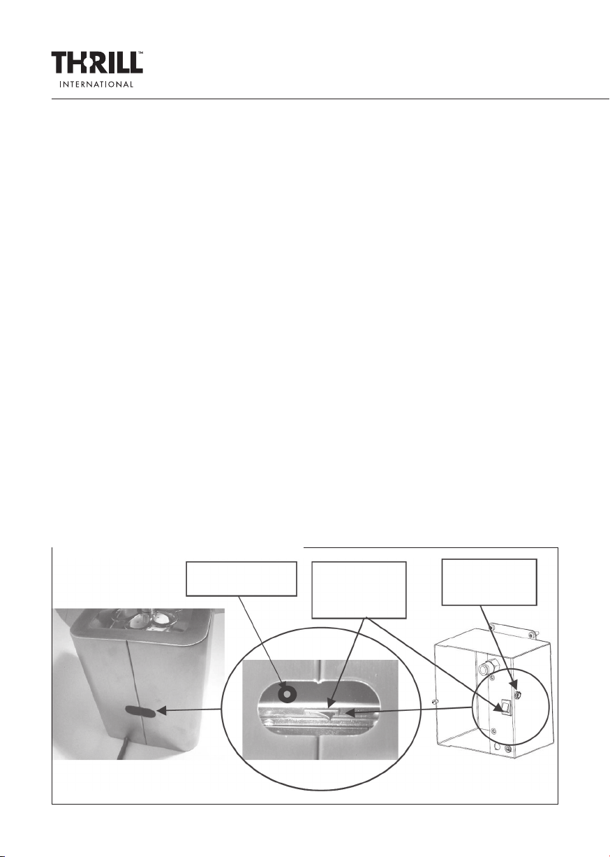
5.1. SET-UP INSTRUCTIONS
Before use, it is necessary to recharge the battery supplied with the appliance. To do this, simply
connect the power cable to the power charger and the low voltage cable to the connection
socket of the sanitizing machine, which is positioned next to the on/o switch, as illustrated in
the diagrams below.
Battery charger
connection Sanitizing
machine
On/o switch
Battery charger
connection
Recharger connection for Thrill Vortex F1 Pro model
GLASSWARE SANITIZING APPLIANCE
User and maintenance manual
RE V. 4
13
ENGLISH
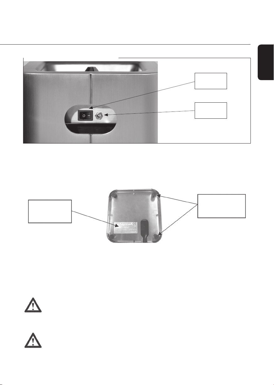
Sanitizing
machine
On/o switch
Battery
charger
connection
The battery takes between 8 and 16 hours to recharge and once fully charged is sucient to
operate the appliance with a 10 litre CO2 cylinder.
When the recharge is completed, the charger must be removed from both the appliance itself
and from the socket and stored in a safe, protected place. The appliance is tted with four
rubber feet so that it can be placed rmly on a worktop as illustrated below:
Appliance
identication
plate
Rubber
support feet
To ensure proper functioning and the safety of those operating the appliance, the machine must be
placed on a dry, smooth, at surface. It must then be connected to a gas cylinder (with dip tube) lled
with E290 food grade CO2 (PLEASE REFER TO THE TECHNICAL DATA SPECIFICATIONS ON CHAPTER 4.3).
Be careful not to excessively bend (minimum bend radius 5 cm) or squash the black supply hose
connecting the cylinder to the appliance, so as to avoid a reduction in or discontinuation of the
CO2 gas supply to the glasses.
DANGER
Use only carbon dioxide that is specied for food use or is marked ‘E290’. The use of
other types of carbon dioxide (e.g. industrial use CO2) cannot guarantee the optimal
levels of hygiene that the appliance can provide and may impart an unpleasant odour to
the glasses thus treated.
DANGER
The machine must always be used in ventilated environments as continued use of the
machine in closed, unventilated spaces may lead to a build-up in the percentage of CO2
present to above 0.5%, which is considered to be potentially hazardous to health.
Recharger connection for Thrill CUBE model
14 This document is the property of THRILL INTERNATIONAL and may not be reproduced without the company’s prior consent.
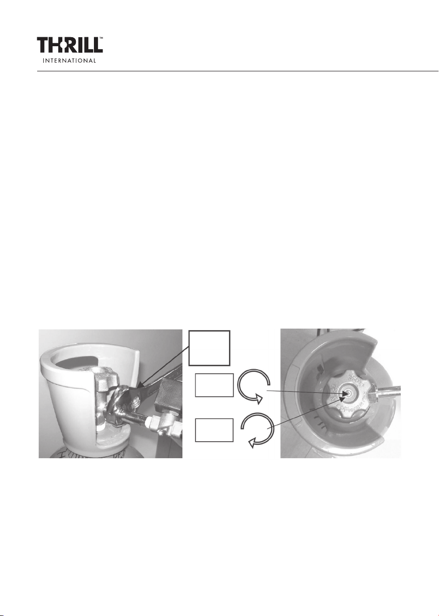
Connection
block
Open
gas ow
Close
gas ow
CAUTION
The dip tube inside the cylinder must be designed to reach a position approximately 2 mm
from the bottom of the cylinder to ensure better use of the carbon dioxide in its liquid
state. The use of cylinders not tted with the appropriate dip tube may hinder the proper
functioning of the appliance and in the event of machine failure resulting from such improper
use, the appliance will not be covered by the warranty.
SAFETY WARNING! Under no circumstances must the gas cylinders used with this appliance
be placed in the vicinity of heat sources or in direct sunlight. ALWAYS ensure that ambient
temperatures do not exceed 40 ° C.
5.2. CONNECTING THE GAS CYLINDER
While the battery is charging, the CO2 cylinder can be connected to the appliance.
To connect the cylinder, follow the steps listed below:
1) Install the cylinder in the desired location, away from naked ames or sources of heat
2) Position the ring nut/ange on the connector tube against the connection thread on the
cylinder
3) Manually screw the connection ring nut/ange to the thread by rotating clockwise until
tight, nish tightening the nut using a No. 27 spanner.
4) Slowly release the CO2 cylinder valve by turning the knob anti-clockwise until it is fully open
and the mechanism locks.
See diagrams below:
5) If, when opening the valve, you can hear CO2 escaping, close the valve, unscrew the
connection, check there is no dust or dirt between the two conical surfaces and following
the steps described above, re-screw the connector to the cylinder.
Before using the appliance, the battery charger and power adapter must be unplugged and
both stored in a safe place for subsequent reuse.
When the need arises to replace the CO2 cylinder, turn o the gas supply from the cylinder and
run the machine on an empty cycle to relieve the gas pressure in the tube, before unscrewing the
connector. Then proceed with the connection of the full cylinder as described previously.

GLASSWARE SANITIZING APPLIANCE
User and maintenance manual
RE V. 4
15
ENGLISH
Be careful when tightening the connection to the cylinder. NEVER turn the black box on the
solenoid valve to tighten the cylinder but instead ALWAYS use spanner No. 27, as previously
illustrated. Valve failure due to rotation during installation is not covered by the warranty.
In any case, avoid opening the black box containing the solenoid valve connected to the cylinder,
as this will result in the expiration of the warranty of the machine.
In case of need, ALWAYS contact the manufacturer.
6. OPERATION AND USE
6.1. COMPATABLE GLASSWARE
The appliance is specically designed for the sanitization of drinking glasses, decanters, jugs
and other containers, generally. The table on page 2 provides approximate time estimates for
sanitizing and chilling/freezing glasses. All sanitizing, cooling and freezing times are inuenced
by climatic and atmospheric conditions (ambient temperature, humidity, and atmospheric
pressure) and changes in these conditions may cause variances in the time required and in the
quantity of C02 consumed to achieve the same results.
6.2. OPERATING INSTRUCTIONS
1) Open the manual valve on the cylinder;
2) Using the switch, turn the appliance to the ON position;
3) Take a glass and place upside down on the rosette wheel;
4) Press down on the rosette wheel; shortly, the gas will ow out from the nozzle at a temperature
of 78.5 degrees below zero; an initial delay in supply (2 - 3 seconds maximum) is not indicative
of the appliance malfunctioning and is due to the length of the pneumatic tube connecting
the cylinder to the appliance;
5) slight variances in the force and quantity of gas supplied are determined by several factors
such as atmospheric pressure, the level of the liquid in the cylinder, temperature and
atmospheric humidity, and again are not an indication of the appliance malfunctioning;
6) After a few moments (see table above) lift the glass to cut o the gas supply; at this point the
glass is chilled, sanitized and ready to use;
7) If you wish to freeze the glass, simply repeat steps 4) and 5) above.
Applying pressure to the glass
on the rosette wheel (step 3)
Glass sanitization (step 4)

16 This document is the property of THRILL INTERNATIONAL and may not be reproduced without the company’s prior consent.
6.3. TROUBLESHOOTING
In the event that the appliance fails to function properly, rst consult the checklist below, as
it could just be a minor problem that the user can resolve by himself.
DANGER! Never attempt to repair the appliance yourself.
Important: should it become apparent that gas is leaking from the nozzle of the appliance even
when idle, stop use immediately and contact Thrill International to arrange for the appliance to
be sent to its laboratory in order to carry out any necessary maintenance and repairs.
7. VORTEX SBI APPLIANCE
7.1. APPLIANCE DESCRIPTION
The Vortex SBI appliance, the built-in version of the Vortex F1 Pro model and diers in that it is
designed to be installed and tted directly to work tops, making it readily accessible and part of
the work top or dispensing point.
FAULTS POSSIBLE CAUSES/SOLUTIONS
The device does not work Check that the battery is charged
Check that the manual valve on the cylinder is open
Check the power button in the ON position
Presence of dry ice on the surface
of the glass
Manual valve partially open
Humidity in the air
No gas is released when pressing
glass on rosette wheel
Check that the tube between the appliance
and the cylinder is not crushed or attened
Gas cylinder empty
Splashes of liquid appear when gas
activated
Presence of liquid on the tray
Dry out the drip tray
Gas leakage from the machine Stop using the machine
Position of the on/o button
for the activation of the appliance

GLASSWARE SANITIZING APPLIANCE
User and maintenance manual
RE V. 4
17
ENGLISH
7.2. COMPONENTS
Check that the package contains all the following items supplied as standard:
1) Glass sanitizer appliance;
2) power charger
3) Power charger cable
4) Instruction Manual
5) Statement of compliance with EC Directives
6) Kit for mounting the appliance to the worktop.
7.3. INSTALLATION
1) Make a 19.5 x19.5 cm square hole in the chosen work surface, bearing in mind that a gap of 2
cm minimum must be left around the body of the appliance;
2) Mount the appliance to the surface and lock into place with the mounting kit supplied – as
indicated in the gure below;
The technical features of the Vortex SBI are described in the following table:
Model VORTEX SBI
Power adapter for charger 100 – 240 Vac, 50/60 Hz
Battery charger plug CEE 7/16 in compliance with Italian standard CEI 23-5
Maximum power consumption when charging 56 W
Jet spray pressure 1 bar
Spray duration relative to time pressure applied
Level of IP2X protection exclusively when operated internally
Physical characteristics
Operational temperature from +10 to +40 ° C
Maximum operating altitude 2000 meters
Noise generated during spraying 89 dBA
Vibration generated during spraying not sucient to pose any danger
Size and weight of packaging 30 x 30 x 28 cm; weight 7 Kg
Maximum number of stackable units when
packaged
3
Size and weight of sanitizing appliance 20 x 20 x 25 cm
Size and weight of power charger 11.5 x 5 x3 cm; 220 gr,
Power cable length - 140 cm
Size and weight of 4 litre cylinder dia 14; length 59 cm; weight 11.3 Kg
Size and weight of 10 litre cylinder dia19 ; length 76 cm; weight 26 kg
CO2 cylinder connection UNI4406 ISO 5145 Gr2 W 21.7 x 1/14 “Ø 27 x 2
Appliance dimensions once tted into
work top
22 x22 cm
Dimensions of square hole required for
installation
19.5 x 19.5 cm
Thickness of worktop on which to be
mounted
1 to 4 cm

18 This document is the property of THRILL INTERNATIONAL and may not be reproduced without the company’s prior consent.
3) Connect the charger to the machine by inserting the charger plug into the connection socket
on the appliance (see diagram above);
4) Connect the battery charger plug into the mains supply socket, away from water or moisture;
5) Connect the solenoid valve to the CO2 cylinder as indicated in section 5.2 of this manual;
6) Turn on the appliance by pressing the button positioned on the edge of the upper frame;
7) Being careful not to stand too close to the nozzle, perform a preliminary trial/cleaning cycle.
This is necessary to verify that the appliance is working properly and also helps to eliminate
any residues that might have become trapped in the CO2 circuit during the connection of the
CO2 cylinder, for example, or packaging residues.
All other operations of the machine (cylinder installation and removal, cleaning, search faults,
etc.) are the same as those described for the Vortex F1 Pro version of the appliance. Please refer
to the relevant instructions.
8. CLEANING
To ensure the optimal levels of hygiene the appliance is capable of delivering are maintained,
the machine must be cleaned daily to remove all the liquids residues that can accumulate in the
drip tray.
To clean the product, follow these steps:
1) Close the valve on the CO2 cylinder;
2) Place a glass on the rosette wheel and press down to relieve any residual pressure of CO2;
3) Turn o the machine with the power switch;
4) Wait a few minutes until the nozzle reaches room temperature;
5) Unscrew the nozzle, the rosette wheel, the bush/bearing and ring nut/ange and wash in
hot water with a mild detergent; alternatively these can be washed in the dishwasher.
Mounting bracket
for xing appliance
to worktop
Jack inserted into
the appliance
connection socket
Mounting kit

GLASSWARE SANITIZING APPLIANCE
User and maintenance manual
RE V. 4
19
ENGLISH
Having removed the aforementioned parts, clean the drip tray,
removing all residual liquid; wash the inside with a wet sponge
and a mild, low-alkaline detergent suited to cleaning stainless
steel; be careful not to allow any dirt or water to enter the CO2
connection tube (see the adjacent illustration)
6) After cleaning the machine, reassemble the parts in reverse
order to when disassembling the parts (see point 5)
9. END OF PRODUCT LIFE AND DISPOSAL INSTRUCTIONS
9.1. END OF PRODUCT LIFE
When the appliance has reached the end of its serviceable life, it must be dismantled and
disposed of in the proper manner. If the machine needs to be stored prior to disposal, it must be
rendered unusable by taking the following steps:
Remove the power cable from the charger;
Close the valve on the CO2 cylinder and remove the connection tube.
9.2. DISPOSAL
Within the European Union, products carrying the symbol illustrated on
the left of the crossed out wheelie bin must be disposed of separately.
This applies to both the product and all accessories marked with the
aforementioned symbol. All products thus marked must not be disposed of
with regular household waste, but must be delivered to a collection centre
for recycling electrical and electronic equipment. Recycling helps to reduce
raw material consumption and environmental pollution.
Packaging
Dispose of the packaging in compliance with the environmental regulations
foreseen for your country.
CO2connection tube

20 This document is the property of THRILL INTERNATIONAL and may not be reproduced without the company’s prior consent.
10. WARRANTY CONDITIONS
Machine: sanitizing glass cleaner
Models: CUBE, VORTEX F1 PRO and VORTEX SBI
This device has a total warranty of two years from the date of purchase, for private and a
warranty of one year for companies.
It has been made carefully and properly tested before the delivery. You need to keep the bill or
the invoice as proof of purchase.
If you happen to be in need of intervention of warranty, please contact the manufacturer.
Devices can be xed only if there is a copy of the bill/invoice attached.
Warranty covers defections due to material or fabrication only and NOT for delivery damage,
small parts aected by usury or fragile parts I.E. Buttons switch or other components which
come from other manufacturers (except the tank CO2).
The product is destinated both for domestic use and for professional use.
Warranty will not be valid in case of tampering, in case of inappropriate use or if someone
dierent from our support team or our manufacturer will attempt to x it.
The warranty doesn’t put any limit to the legal rights of the purchaser. The warranty period will
not be extended in case of intervention. This is for substitution of damaged parts or xed ones.
If the purchaser notices some defection or dameges at the moment of purchase, they must be
immediately communicated, and not over one week from the date of purchase.
When the warranty ends, all the intervention can be made just paying them. In many cases,
complaints are due to a wrong use of the device. They can be xed via phone easily. Manufacturer
has activate a “reply service” which helps our customers via phone calls:
THRILL INTERNATIONAL S.R.L.
Via Ipplis 101
33100 Udine - ITALY
Tel. +39 0432 582374
www.thrillinternational.com
support@thrillinternational.com
Other manuals for VORTEX F1-PRO
2
This manual suits for next models
2
Table of contents
Languages:
Other THRILL Accessories manuals


Popular Accessories manuals by other brands


Opitec
Opitec TCF-S Technical manual

Secutron
Secutron MRI-2351RAP Installation and maintenance instructions

KMC Controls
KMC Controls STW-6010 installation guide

Kistler
Kistler 6184AC Series Quick Start Installation

LEGRAND
LEGRAND Wattstopper CU-250 installation instructions

Allergy Amulet
Allergy Amulet AMULET quick start guide