THRILL VORTEX F1-PRO Operating instructions
GLASSWARE SANITIZING APPLIANCE
USER AND MAINTENANCE MANUAL
MACCHINA SANIFICATORE DI BICCHIERI
MANUALE DI USO E MANUTENZIONE
DATA PRIMA EMISSIONE
FIRST ISSUE
REVISIONE
REVISION
DATA ULTIMA REVISIONE
LAST ISSUE
05/12/2014
05 DEC 2014
7
01/03/2021
01 MAR 2021


The content of this document is the property of THRILL INTERNATIONAL. Reproducon without permission is prohibited.
ENGLISH
3
GLASSWARE SANITIZING APPLIANCE
USER AND MAINTENANCE MANUAL
www.thrillinternational.com
GLASSWARE SANITIZING APPLIANCE
USER AND MAINTENANCE MANUAL (REV. 7)
4
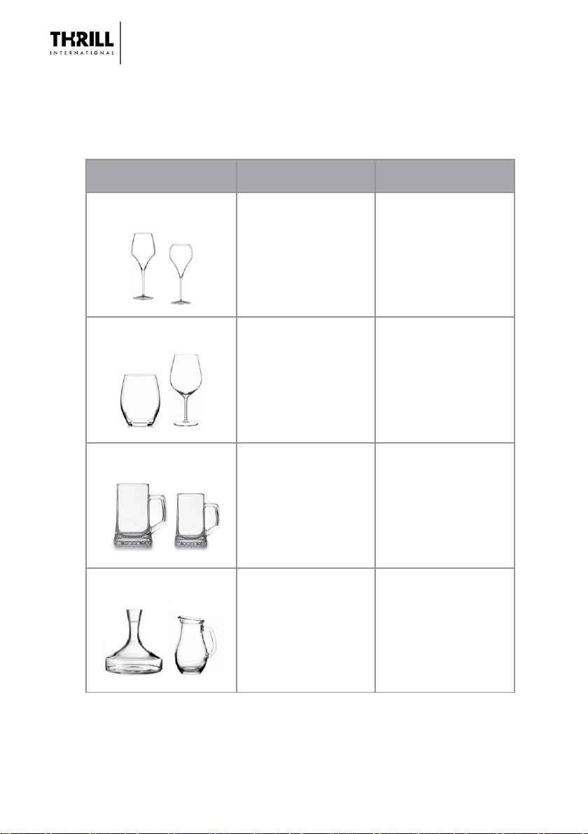
NUMBER AND DELIVERY TIMES IN ACCORDANCE WITH THE
TYPE OF GLASSES TO SANITIZE
TYPE OF
GLASSWARE
SANIFICATION
AND CHILLING
SANIFICATION
AND FREEZING
1 shot
Time 2 seconds
10 grams
1 shot
Time 3 seconds
15 grams
1 shot
Time 4 seconds
20 grams
1 shot
Time 5 seconds
25 grams
2 shot
Time 2 + 2 seconds
20 grams
2 shot
Time 3 + 2 seconds
25 grams
3 shot
Time 4 + 3 seconds
35 grams
2 shot
Time 5 + 5 seconds
50 grams
Small glass
Medium glass
Large glass
Tankard/Jug
NOTE: On ERT models (Tube lenght 8-12 meters) the CO2 consumpon is 15% higher
than the standard model.

The content of this document is the property of THRILL INTERNATIONAL. Reproducon without permission is prohibited.
ENGLISH
5
1. GENERALINFORMATION.............................................................................6
1.1. QUICK START..................................................................................... 6
1.2. MODELS .............................................................................................. 6
1.3. COMPOSITION OF THE MACHINE.............................................. 7
2. IDENTIFICATION OF PARTS .........................................................................7
3. SAFETYINSTRUCTIONS ............................................................................... 8
3.1. INTENDED USE AND PURPOSE ................................................... 8
3.2. SAFETY WARNINGS ........................................................................ 9
3.3. DANGERS............................................................................................9
4. APPLIANCE DESCRIPTION AND
TECHNICALSPECIFICATIONS ...................................................................10
4.1. SANIFICATION ................................................................................ 10
4.2. APPLIANCE PARTS ......................................................................... 11
4.3. TECHNICALSPECIFICATIONS ..................................................... 14
5. INSTALLATION.................................................................................................15
5.1. SET-UPINSTRUCTIONS ................................................................ 15
5.2. CONNECTING THE GAS CYLINDER ......................................... 17
6. OPERATIONAND USE ................................................................................. 18
6.1. COMPATIBLE GLASSWARE ........................................................ 18
6.2. OPERATING INSTRUCTIONS ..................................................... 19
6.3. TURN OFF THE MACHINE ......................................................... 19
6.4. TROUBLESHOOTING ................................................................... 20
7. THRLLVORTEX SBI ....................................................................................... 22
7.1. APPLIANCE DESCRIPTION ......................................................... 22
7.2. COMPONENTS ............................................................................... 22
7.3. INSTALLATION ................................................................................ 22
8. THRILL VORTEX TAP .................................................................................... 23
9. THRILL VORTEX WOOD ............................................................................. 24
10. 8 AND12METERSTUBES .........................................................................25
11. CLEANING .......................................................................................................26
12. END OF PRODUCT LIFE AND
DISPOSAL INSTRUCTIONS ...................................................................... 26
12.1. END OF PRODUCT LIFE ............................................................. 26
12.2. DISPOSAL ...................................................................................... 27
13. WARRANTY CONDITIONS ..................................................................... 28
These user instrucons are the translaon of the original user instrucons wrien
in italian language.
GLASSWARE SANITIZING APPLIANCE
USER AND MAINTENANCE MANUAL (REV. 7)
6
1. GENERAL INFORMATION
1.1. QUICK START
To start the machine carry out the following acons:
1. Unpack the machine, retaining the packaging for any future shipment;
2. Install the machine on a at surface;
3. Place the CO2 cylinder in a place away from and protected from heat;
4. Connect the CO2cylinder with siphon tube to the solenoid valve, as described in
secon 5.2 of this manual and open the cylinder valve;
5. Connect the charger to the exisng outlet on the appliance (see gure at centre
of page 13);
6. Connect the charger to a power outlet with a voltage between 100 and 240 Vac
and leave to charge for between 8 and 16 hours;
7. When fully-charged, disconnect the charger from the outlet and then from the
appliance and store it in a dry place;
8. Turn on the machine and run on an empty cycle to clean the machine; please note
that this stage may be accompanied by the emission of certain odours resulng
from material residues from the packaging;
9. At the end of the cycle, turn o the machine using the proper switch.
IMPORTANT NOTE: It is essenal that you read all parts of this manual fully and
thoroughly before operang the machine.
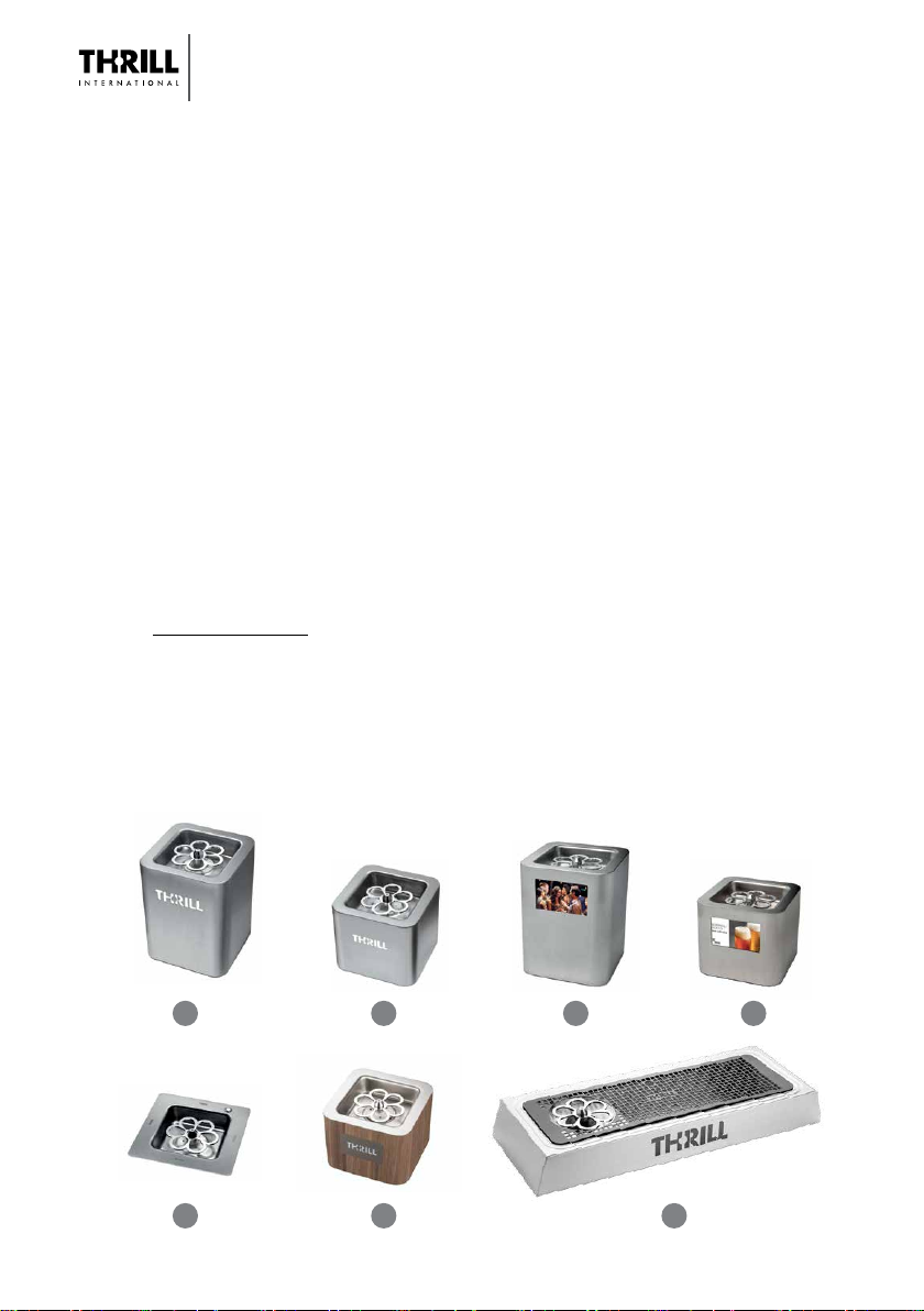
1.2. MODELS
1. Thrill Vortex F1 PRO 2. Thrill Vortex CUBE 3. Thrill Vortex F1 PRO LCD
4. Thrill Vortex CUBE LCD 5. Thrill Vortex SBI 6. Thrill Vortex WOOD
7. Thrill Vortex TAP
1 2
5
3 4
6 7

The content of this document is the property of THRILL INTERNATIONAL. Reproducon without permission is prohibited.
ENGLISH
7
Electrovalve group;
CO2Cylinder
connecon
Sanizing machine Baery charger and
mains cable
User and
maintenance manual
Declaraon of
conformity
DECLARATION
OF
CONFORMITY
The rst secon of this manual is applicable to all versions, except for the posion
of the POWER ON switch on the SBI built-in model (see previous pictures); the SBI
model is described in detail in the second part of this manual.
1.3. COMPOSITION OF THE MACHINE
Verify that the contents of the packaging are composed by the following material:
• Sanizing machine with wired electrovalve;
• Baery charger from mains;
• Mains cable;
• User and maintenance manual;
• Declaraon of conformity
• NSF Cercate on the idenfying label with the S/N
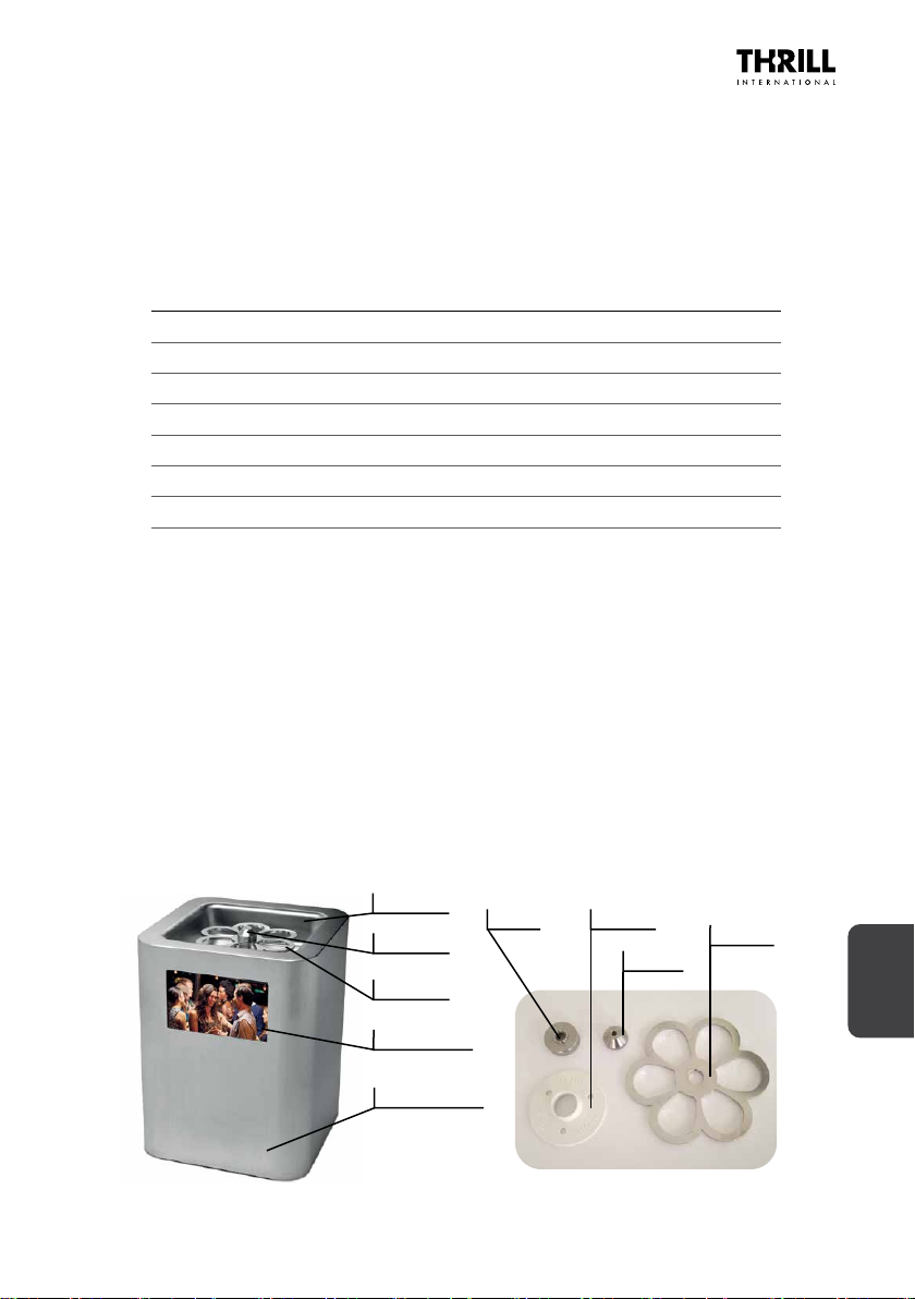
2. IDENTIFICATION OF PARTS
The various parts are connected to each other as illustrated by the image on the
following page >>
Label with NSF
cercate

GLASSWARE SANITIZING APPLIANCE
USER AND MAINTENANCE MANUAL (REV. 7)
8
3. SAFETY INSTRUCTIONS
• Please read this instrucon manual carefully before aempng to operate the
appliance for the rst me, and comply with all safety instrucons!
• The appliance must only be used for the purposes and in the manner described
in these instrucons.
• Please keep these instrucons for future reference.
• Any appliance sold or passed on to third pares must be accompanied by the
instrucon Manual and declaraon of conformity.
• The use of all models of the Thrill appliance does not preclude the need to wash
and sterilize glasses, which must be thoroughly cleaned aer each use.
3.1. INTENDED USE AND PURPOSE
This appliance, which funcons using jets of carbon dioxide, is designed expressly for
the purpose of sanizing and cooling glasses or glass and plasc containers.
It is intended for both professional and home use.
Use of the appliance in small areas requires the presence of adequate venlaon
in order to prevent the build-up of toxic fumes harmful to human health (i.e,
concentraons above 0.5% of CO2).

The content of this document is the property of THRILL INTERNATIONAL. Reproducon without permission is prohibited.
ENGLISH
9
3.2. SAFETY WARNINGS
Please pay aenon to the safety symbols used in this instrucon manual, which
are as follows:
Where needed, the following safetywarnings have been used in there
instrucons for use.
DANGER! High risk: Failure to observe this warning may result in fatal
injury or serious material damage
HAZARD WARNING: Medium Risk: Failure to observe this warning may result in
injury or serious material damage.
CAUTION: Low risk: Failure to follow this warning may result in minor injury or
material damage.
3.3. DANGERS
The potenal dangers associated with the appliance during various stages of its
operaon and use are listed below:
- DANGER TO CHILDREN AND THE THOSE WITH DISABILITIES
Children should not be allowed to play with any of the packaging material or protecve
plasc bags. Please keep the appliance out of the reach of children and always
maintain a watchful eye when children are in the vicinity of the machine.
The appliance is not suitable for use by children, by adults with limited physical,
mental, or intellectual capacies, or those lacking necessary experience.
Ensure that children do not play with the appliance, knock it over, cause the adapter
to fall, or tamper with the CO2.cylinder.
- POWER SUPPLY
• To avoid the risk of electric shock, protect the appliance from humidity and damp
condions, splashes of water or moisture.
• Do not use the appliance outdoors or near water-lled receptacles, such as sinks.
• Make sure that the support base beneath the unit is dry.
• Do not use the appliance if the power supply unit or power cable are damaged
in any way or if the machine itself has been previously knocked over or dropped.
• To avoid risk, do not modify or make any changes to the product. Do not replace
the connecon cable yourself.
• In case of the need for repair, do not aempt such repairs yourself. Only have
your appliance repaired by our service centre or laboratories authorized by Thrill
Internaonal.
• In the event that liquids penetrate the appliance casing or foreign objects fall into
the appliance, immediately disconnect the plug from the electrical supply.
Have the appliance safety checked before operang it.
The appliance casing, power cable, power adapter, and plug must not be immersed
in water or other liquids. However, if the appliance falls into water or other liquid,
immediately remove the plug from the electricity supply. Under no circumstances
touch or aempt to remove the appliance unl you have done so.
Do not aempt to use the appliance unl a specialist laboratory has checked it.
Do not touch the power supply with wet hands.

GLASSWARE SANITIZING APPLIANCE
USER AND MAINTENANCE MANUAL (REV. 7)
10
Connect the plug only to a properly installed and easily accessible socket, the
voltage of which corresponds to the indicaons on the nameplate. The socket must
be easily accessible even aer connecon.
Make sure that the power cord can not be damaged by sharp edges or hot spots.
Even aer switching o, the appliance is not completely disconnected from the
mains. To isolate it completely from the power supply, pull out the mains plug from
the socket.
When posioning the appliance, make sure that the power cord is not throled or
pinched. To remove the plug from the socket, always pull at the plug and never the
cable.
The power supply line must be protected by an RCD with IΔn = 30 mA, instantaneous
trip; if in doubt consult a qualied installer.
- HYGIENE
The appliance must be cleaned regularly in order to prevent the growth of bacteria.
Do not place dirty glasses containing liquid residues on the grille.
Avoid the build-up of liquid in the drip tray.
While the sanizing acon combats the build-up of bacteria in glassware, it is not a
substute for the cleaning and sanizaon performed by a dishwasher.
- USE
Never look directly into the jet stream or directly expose it to parts of the body
(face, hands, arms, etc.), in order to avoid the risk of frost burn.
Avoid placing your hands inside the basin during operaon or immediately aer
appliance use.
Before using the appliance, ensure it is completely dry, as the presence of water in
the tank can lead to splashing and potenal frostbite; if liquids have accumulated in
the drip tray, dry it thoroughly.
There is a risk that protecve treatments and nishes applied to work surfaces may
cause the rubber feet ed to the appliance to corrode or become stuck to the
surface; to ensure this does not occur, place a non-slip base or mat under the machine.
Do not use detergents or acids for cleaning surfaces; only use products specically
suitable for cleaning stainless steel.
Clean all exterior surfaces of the machine by hand; the nozzle, rosee and
accompanying parts can be washed in a dishwasher.
4. APPLIANCE DESCRIPTION AND
TECHNICAL SPECIFICATIONS
4.1. SANIFICATION
The sanizing appliance is designed to reduce the presence and build-up of bacteria
in ready to use glasses and plasc containers by means of a rapid chilling acon using
jets of food grade liquid carbon dioxide (E290).
This process not only eliminates most of the pathogens present on the inner surface
and on the edge of the glass or container but also has a cooling or chilling eect, thus
enhancing the taste of the contents.
The process consists of blasng the inside of the glass with a jet of carbon dioxide at
78 Celsius degrees below zero, which cools both the interior and surface of the glass.
The content of this document is the property of THRILL INTERNATIONAL. Reproducon without permission is prohibited.
ENGLISH
11
This cooling and sanizaon process reduce the presence of principal micro-
organisms considerably, as the following table reporng the analyses carried out by
the University of Udine demonstrates, thus opmizing glass hygiene.
The degree of reducon of the main microorganisms is shown in the following table
(As per analysis carried out at the University of Udine):
Micro-organism Reducon Percentages
Salmonella Enteridis > 88 %
Staphylococcus Aureus > 83 %
Escherichia Coli > 87 %
Penicillium Nalgiovense > 83 %
Listeria Innocua > 80 %
Pseudomonas Puda > 66 %
Breanomyces Bruxellensis > 50 %
The carbon dioxide is drawn in a liquid state from a special gas cylinder (available
upon request) and converted into a gaseous state upon vaporizaon. Please note
that under certain atmospheric condions dependent upon temperature, humidity
and low atmospheric pressure, etc., dry ice may form on the machine nozzle; this
phenomenon, which may last for a few hours, is by no means abnormal and does not
compromise the funconing of the appliance in any way. Any dry ice on the glass will
evaporate within a few seconds without leaving any trace.
4.2. APPLIANCE PARTS
The appliance consists of the following parts:
- Glassware sanizer, as illustrated in the diagram below:
Removable parts for daily cleaning
Drip Tray
Noozle
Rosee
Machine Body
Bush Colleo
Noozle
Rosee
LCD Display

GLASSWARE SANITIZING APPLIANCE
USER AND MAINTENANCE MANUAL (REV. 7)
12
Most of the parts installed in the tray are removable for easy and accurate washing; the
removal and subsequent reinstallaon operaons are very simple and are described
in the following chapters.
The sanizing machine is connected to the CO2 gas cylinder by means of a screw
connecon and a solenoid valve to regulate the ow of gas to the glasses.
THRILL INTERNATIONAL srl supplies its own gas cylinders but other cylinders may
be used, provided that they have the following characteriscs:
• Connecon: in accordance with UNI4406 ISO 5145 Gr2 W 21,7 x 1/14” Ø 27 x 2;
• Fied with a dip tube
• Fied with a manual valve to shut o the gas supply.
• Fied with an overpressure valve
• Content: food grade CO2(E290)
Thrill Internonal srl can supply, on request, the cylinder aacks for other countries,
for example USA, Japan, China, Russia, etc.
The machine is connected to the supply solenoid valve through a 2.8 meters long pipe.
If there is a need to increase the length of the pipe, a special version is available with
a pipe length of 8 or 12 meters and with a double solenoid valve.
In this case the selecon of the length of the piping must be carried out at the me
of ordering.
For pipe lengths over 2.8 meters, there may be a slight delay, contained in a few
seconds, between the pressure of the rosee and the delivery of CO2.
This delay is due to the passage of the gas inside the pipe and does not represent a
malfuncon of the machine
- Baery Charger
The baery charger charges the baery ed inside the appliance thus eliminang
the need for a power supply and allowing the device to be used for mobile banquets
or other outdoor events.
Please note the following: the me required to charge the appliance is between 8
and 16 hours; the charger must only be connected to the appliance when the baery
is very low; do not aempt to charge the appliance using chargers other than that
supplied as this may damage the appliance, causing it to malfuncon, and is not
covered by the warranty.
- CO2 Bole (Cylinder)
The CO2 bole is not supplied as standard but represents an oponal product, which
can be supplied on request.
Thrill Internaonal sells 2 types of cylinders made for opmal operaon of its
machinery:
1) 4 kg bole for sanizing and cooling about 150 glasses;
2) 10 kg bole for sanizing and cooling about 400 glasses.
If you use a cylinder not marketed by Thrill Internaonal, remember that it must have
an overpressure valve to protect the user in case of overpressure inside the cylinder.
The machine must be connected to a tank with a dip tube and lled with CO2E290
food grade. Be careful not to bend excessively (minimum bend radius of 5 cm) or
crush the black connecng tube between the cylinder and the machine, in order to
avoid the reducon or interrupon of the CO2 gas ow towards the glasses.
The content of this document is the property of THRILL INTERNATIONAL. Reproducon without permission is prohibited.
ENGLISH
13
- Baery
The baery used in the machine is a LEAD-GEL 12 V 5 Ah Lithium-free baery.
It is not accessible to the user and if a replacement is required, said replacement
must be performed by authorized personnel only and using spare parts with the
same characteriscs.
If the machine is not in use, the baery must be recharged every 6 months; failure
to this recommendaon could cause baery damage that is not covered by warranty
- Display
The display represents the interface between the user and the machine, providing
images that aract the aenon of people near the appliance and is installed on the
F1 Pro and Cube units.
The color display is 108 * 65 mm, 800 * 480 pixel denion and can reproduce
pictures and movies in dierent formats.
The les to be played are loaded into a USB key (supplied with the appliance) and
are connuously played.
The les are reproduced on the display in the same sequence as they are loaded on
the USB sck; the image les can be of any size and may be scaled to the size of the
display if necessary, while the video les are limited to a maximum playing me of 5
minutes per le; if the le has a longer duraon the reproducon is interrupted and
the display jump to the next le.
When the power is turned on, the preloaded les in the internal memory are rst
played, then the les loaded by the Customer are played in the USB key.
Take care to ALWAYS engage and disengage the USB key with the machine o.
To upload les to the USB key, simply insert it into a PC or MAC and copy the desired
les to the root of the USB key.
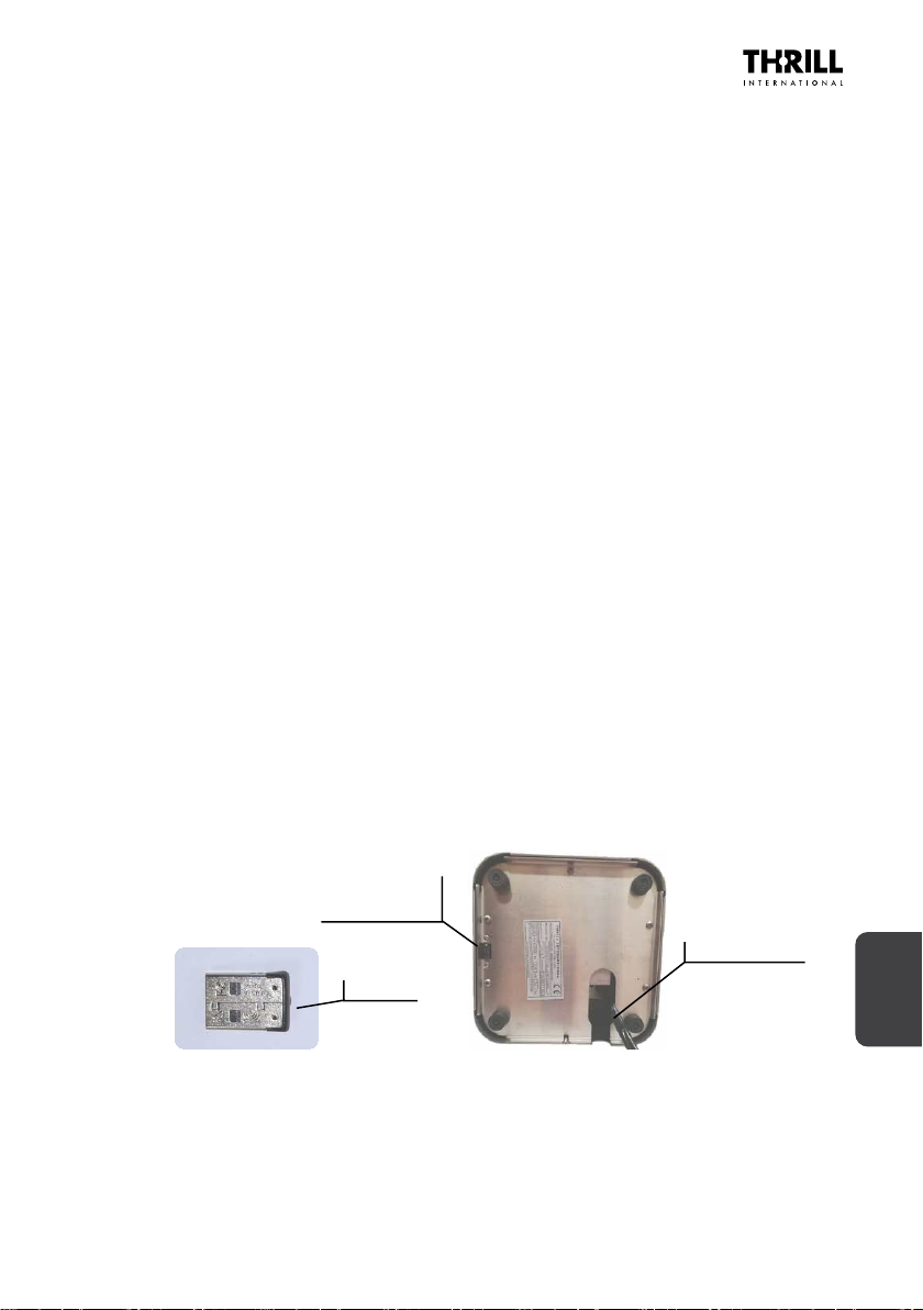
Aer loading the les on the USB key, the key must be inserted on the boom of
the machine, see the following gures:
NOTE: Use only USB keys “short” or “mini” that do not have to touch the surface
or liquids.
USB Key
Inseron Point
of the USB Key
Gas Tube Entry

GLASSWARE SANITIZING APPLIANCE
USER AND MAINTENANCE MANUAL (REV. 7)
14
4.3. TECHNICAL SPECIFICATIONS
Common technical characteriscs
Power adapter for charger 100 – 240 Vac, 50/60 Hz
Baery charger plug Italiana CEE 7/16 secondo CEI 23-5
Maximum power consumpon when charging 56 W
Jet spray pressure 1 bar
Spray duraon Proporonal to me pressure applied
Level of protecon IP2X exclusively when operated internally
Common physical characteriscs
Working temperature From +10 to +40 °C
Maximum operang altude 2000 meters
Noise level when spraying 89 dBA
Vibraons generated during spraying are not sucient to pose any danger
Maximum number of stackable packages
5
Dimensions and weight of power supply
11,5 * 5 * 3 cm; 220 gr; power supply cable lenght 140 cm
CO2 cylinder connecon UNI4406 ISO 5145 Gr2 - W 21.7 x 1/14” Ø 27 x 2
Specic physical characteriscs THRILL VORTEX F1 PRO
Dimensions and weight of packaged product 42 * 34 * 34 cm; weight 9.2 Kg
Appliance dimensions and weight 20 * 20 * 25,7 cm; weight 6.9 Kg
Specic pysical characteriscs THRILL VORTEX CUBE
Dimensions and weight of packaged product 42 * 34 * 34 cm; weight 8.0 Kg
Appliance dimensions and weight 20 * 20 * 17 cm; weight 6.0 Kg
Specic physical characteriscs THRILL VORTEX SBI
Dimensions and weight of packaged product 42 * 34 * 34 cm; weight 6.5 Kg
Appliance dimensions and weight 22,2 * 22,2 * 16 cm; weight 4,5 kg
Specic physical characteriscs THRILL VORTEX CUBE LCD
Dimensions and weight of packaged product 42 * 34 * 34 cm; weight 8.0 Kg
Appliance dimensions and weight 20 * 20 * 17 cm; weight 6.0 Kg
Specic physical characteriscs THRILL VORTEX F1 PRO LCD
Dimensions and weight of packaged product 42 * 34 * 34 cm; weight 8.9 Kg
Appliance dimensions and weight 20 * 20 * 25,7 cm; weight 7.0 Kg
Specic physical characteriscs THRILL VORTEX TAP
Dimensions and weight of packaged product 71 * 31 * 21cm; weight 9,0 Kg
Appliance dimensions and weight 20 * 20 * 17 cm; weight 6.3 Kg
Specic physical characteriscs THRILL VORTEX WOOD
Dimensions and weight of packaged product 42 * 34 * 34cm; weight 7,0 Kg
Appliance dimensions and weight 20 * 20 * 15 cm; weight 5.0 Kg

The content of this document is the property of THRILL INTERNATIONAL. Reproducon without permission is prohibited.
ENGLISH
15
5. INSTALLATION
NOTE
On rst use, there may be ny scraps of debris remaining on the product from the
packaging material; the product may also emit an odour.
To ensure the machine is clean and ready to use, rst run the machine on an empty cycle.
The appliance is delivered in sturdy cardboard packaging; gently remove the individual
parts from the box and lay them out on a at surface. Check that the contents are
complete and that all the following items are included:
1) Glassware sanizing machine (appliance)
2) Baery charger
3) Power adapter
4) Instrucon Manual and 2 years warranty
5) Statement of Compliance with EU direcves.
6) NSF Cercaon on the label with S/N number
If one or more parts is missing, please contact the distributor or product manufacturer.
5.1. SET-UP INSTRUCTIONS
Before use, it is necessary to recharge the baery supplied with the appliance.
To do this, simply connect the power cable to the power charger and the low voltage
cable to the connecon socket of the sanizing machine, which is posioned next
to the on/o switch, as illustrated in the following pictures:
NOTE: The two models TAP and SBI have the posion of the power ON switch
and the connector for baery recharging in dierent posions, as shown
in the gures on the following page >>
Power ON/OFF switch
Baery recharge connector

GLASSWARE SANITIZING APPLIANCE
USER AND MAINTENANCE MANUAL (REV. 7)
16
The baery takes between 8 to 16 hours to be recharged; once fully charged is suf-
cient to operate the appliance for 7 to 10 days of normal service.
When the recharge is completed, the charger must be removed from both the appli-
ance and from the mains socket and stored in a safe, protected place.
The appliance is ed with four rubber feet so that it can be placed rmly on a
work-top as illustrated below.
Idencaon Label
Rubbery Support Feet
To ensure proper operaons and the safety of personnel operang the appliance,
the machine must be placed on a dry, smooth, at surface.
DANGER
Use only carbon dioxide that is specied for food use or is marked ‘E290’.
The use of other types of carbon dioxide (e.g. industrial use CO2) cannot
guarantee the opmal levels of hygiene that the appliance can provide and
may impart an unpleasant odour to the glasses thus treated.
THRILL VORTEX TAP THRILL VORTEX SBI THRILL VORTEX SBI Top view
Power ON
switch Power ON
switch
Baery recharge
connector Baery recharge
connector
The content of this document is the property of THRILL INTERNATIONAL. Reproducon without permission is prohibited.
ENGLISH
17
DANGER
The machine must always be used and maintained in venlated environments
as connued use of the machine in closed, unvenlated spaces may lead
to a build-up in the percentage of CO2 present to above 0.5%, which is
considered to be potenally hazardous to health.
CAUTION
The dip tube inside the cylinder must be designed to reach a posion approximately
2 mm from the boom of the cylinder to ensure beer use of the carbon dioxide
in its liquid state. The use of cylinders not ed with the appropriate dip tube may
hinder the proper funconing of the appliance and in the event of machine failure
resulng from such improper use, the appliance will not be covered by the warranty.
SAFETY WARNING! Under no circumstances must the gas cylinders used with this
appliance be placed close to heat sources or in direct sunlight. ALWAYS ensure that
ambient temperatures do not exceed 40 ° C.
5.2. CONNECTING THE GAS CYLINDER
While the baery is charging, the CO2cylinder can be connected to the appliance.
To connect the cylinder, follow the steps listed below:
1. Install the cylinder in the desired locaon, away from naked ames or sources
of heat
2. Posion the ring nut/ange on the connector tube against the connecon thread
on the cylinder
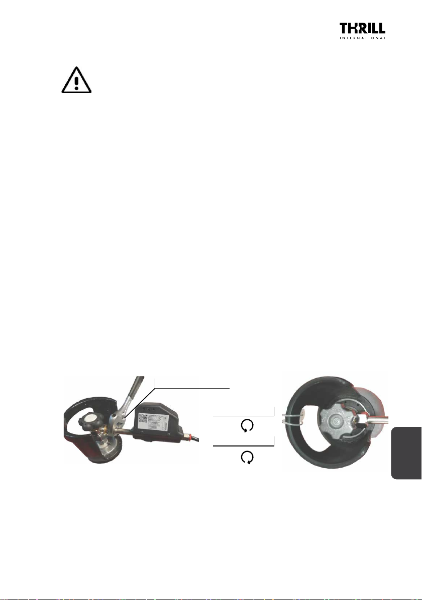
3. Manually screw the connecon ring nut/ange to the thread by rotang clockwise
unl ght, nish ghtening the nut using a N. 27 spanner.
4. Slowly release the CO2 cylinder valve by turning the knob an-clockwise unl it
is fully open and the mechanism locks.
Locking the Nut
Open the valve
Close the valve
See the following pictures:
5. If, when opening the valve, you can hear CO2escaping, close the valve, unscrew
the connecon, check there is no dust or dirt between the two conical surfaces
and, following the steps described above, re-screw the connector to the cylinder.
Before using the appliance, the baery charger and the power cable must be
unplugged and both stored in a safe place for subsequent reuse.
GLASSWARE SANITIZING APPLIANCE
USER AND MAINTENANCE MANUAL (REV. 7)
18
If it is necessary to replace the CO2 cylinder, before unscrewing the nut from the
thread it is necessary to close the gas supply from the cylinder and carry out an empty
cycle to discharge the pressure of the gas present inside the pipes.
Then proceed with the connecon of the new full tank as described previously.
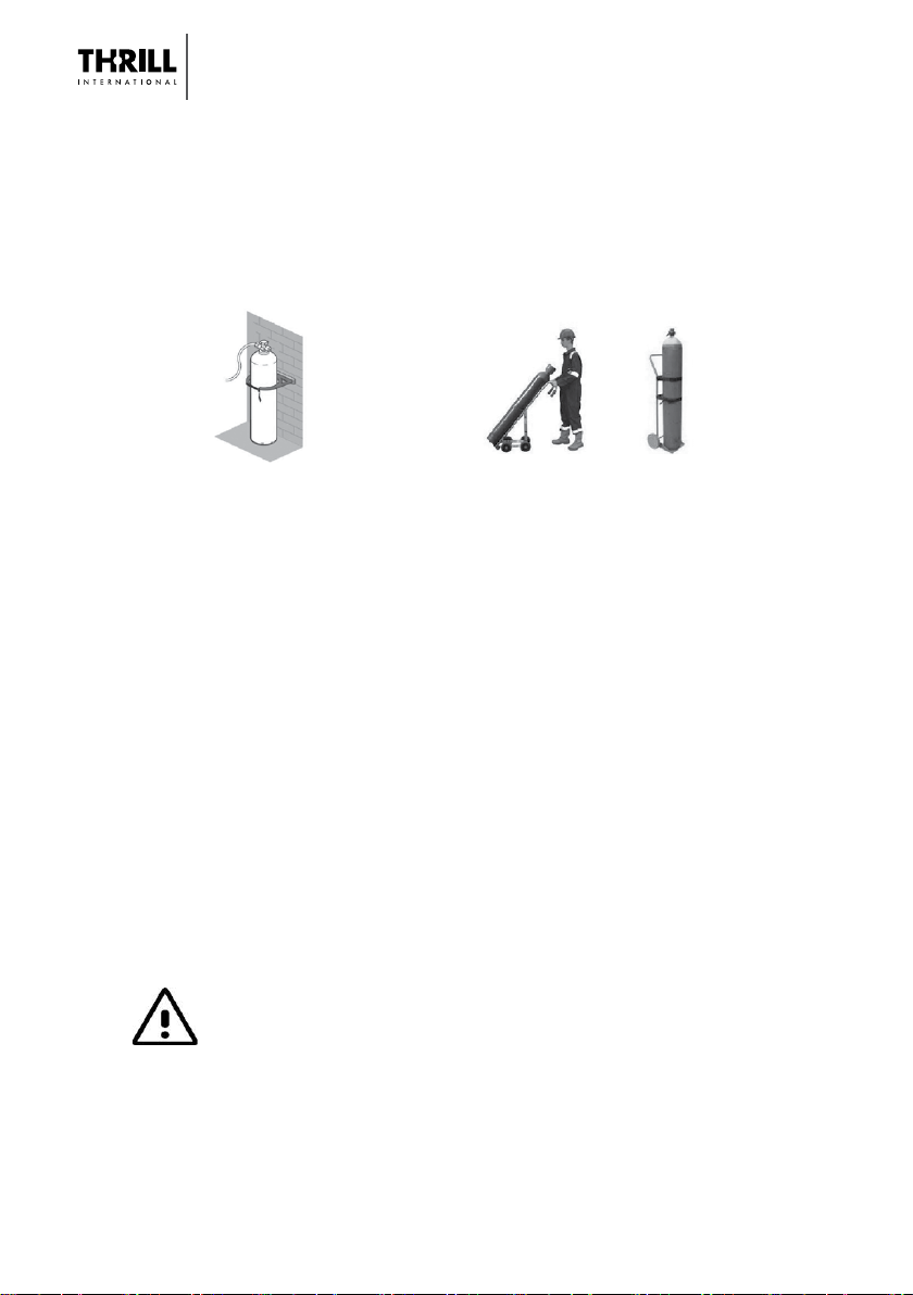
The cylinders (both full and empty) must always be transported with the appropriate
trolley and must be stored in a vercal posion, held in posion by chains or straps.
Avoid using damaged cylinders or showing signs of corrosion.
Be careful to NEVER ghten the ng to the cylinder by turning the black box
of the solenoid valve, but ALWAYS using N. 27 spanner as shown in the previous
gures. Any failure of the solenoid valve due to its rotaon during installaon is not
covered by warranty.
6. OPERATION AND USE
6.1. COMPATIBLE GLASSWARE
The appliance is specically designed for the sanizaon of drinking glasses,
decanters, jugs and other containers, generally.
The table on page 2 provides approximate me esmates for sanizing and chilling/
freezing glasses. All sanizing, cooling and freezing mes are inuenced by climac
and atmospheric condions (ambient temperature, humidity, and atmospheric
pressure) and changes in these condions may cause variances in the me required
and in the quanty of CO2consumed to achieve the same results.
IMPORTANT!
It is strongly discouraged to use low quality glasses, obtained with re-glazed
glass or produced using 2 dierent types of glass, as they are highly prone
to unpleasant cracking or breakage.
In this case, suspend the sanizing and cooling acvies on the specic
type of glass subject to cracking and/or breakage.
As a rule of thumb to recognize a low-quality glass is to verify the specic
weight of the glass, which is approximately half of a normal glass.
Cylinder Hold in Place CO2 Cylinder Transportaon
The content of this document is the property of THRILL INTERNATIONAL. Reproducon without permission is prohibited.
ENGLISH
19
6.2. OPERATING INSTRUCTIONS
1. Open the manual valve on the cylinder;
2. Using the switch, turn the appliance to the ON posion;
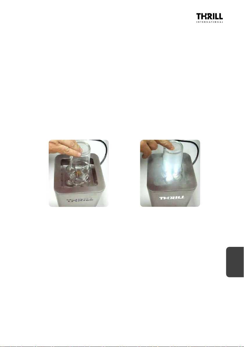
3. Take a glass and place upside down on the rosee wheel;
4. Press down on the rosee wheel; shortly, the gas will ow out from the nozzle at
a temperature of 78 Celsius degrees below zero; an inial delay in supply (2 - 3
seconds maximum) is not indicave of the appliance malfunconing and is due
to the length of the pneumac tube connecng the cylinder to the appliance;
5. Slight changes in the force and quanty of gas supplied are determined by several
factors such as atmospheric pressure, the level of the liquid in the cylinder,
temperature and atmospheric humidity, and again are not an indicaon of the
appliance malfunconing;
6. Aer a few moments (see table above) li the glass to cut o the gas supply; at
this point the glass is chilled, sanized and ready to use;
7. If you wish to freeze the glass, simply repeat steps 4) and 5) above.
6.3. TURN OFF THE MACHINE
To turn o the machine, carry out the following operaons:
1. Close the manual valve of the CO2 cylinder;
2. Press the upper rosee for a few seconds and in any case unl no more gas comes
out of the nozzle;
3. Turn o the power switch on the side of the machine;
4. Eventually (if necessary) connect the charger to recharge the internal baery.
NOTE: It is necessary to recharge the machine when there is no gas supply when the
rosee is pressed and / or the LEDs under the canopy do not light up.
Press the glass on the rosee,
point 3)
Sanizing and chilling, point 4)

GLASSWARE SANITIZING APPLIANCE
USER AND MAINTENANCE MANUAL (REV. 7)
20
6.4. TROUBLESHOOTING
In the event that the appliance fails to funcon properly, rst consult the checklist
below, as it could just be a minor problem that the user can solve by himself.
DANGER
Never aempt to repair the appliance yourself.
NOTE: In case of malfuncon, contact the THRILL Assistance service by
* IMPORTANT!
Should it become apparent that gas is leaking from the nozzle of the appliance
even when idle, stop use immediately and contact Thrill Internaonal to arrange
for the appliance to be sent to its laboratory in order to carry out any necessary
maintenance and repairs.
FAULTS POSSIBLE CAUSES/SOLUTIONS
The device does not work
Check that the baery is charged
Check that the manual valve on the cylinder is open
Check the power buon in the ON posion
Presence of dry ice on the
surface of the glass
Manual valve parally open
Humidity in the air
No gas is released when
pressing glass on rosee wheel
Check that the tube between the appliance and the
cylinder is not crushed or aened
Gas cylinder empty.
Splashes of liquid appear when
gas acvated
Presence of liquid on the tray
Dry out the drip tray
Gas leakage from the machine Stop using the machine (*)
Low gas supply Solenoid valve lter dirty
Other manuals for VORTEX F1-PRO
2
This manual suits for next models
6
Table of contents
Languages:
Other THRILL Accessories manuals


Popular Accessories manuals by other brands


schmersal
schmersal EX-BNS 303-2187 operating instructions

NeuLog
NeuLog NUL-211 Guide

Zephyr
Zephyr Duct Cover Extension Z1C-00HZ installation instructions

CityGrow Systems
CityGrow Systems CG500MS installation guide

National Instruments
National Instruments D000017 Rev B user manual

JAR Systems
JAR Systems A4-USBC-PB user manual

Profile
Profile ADAGIO PAC-312 user manual

Orno
Orno OR-CR-263 Operating instruction

DigitalHome
DigitalHome Smart DB300 quick start guide

Tascam
Tascam IF-88AE owner's manual

BAPI
BAPI CO2 Duct Installation & operating instructions

PCB Piezotronics
PCB Piezotronics ICP M109C12 Installation and operating manual