Opitec TCF-S User manual

MODEL TCF-S
TEMPERATURE
COMPENSATING
FOCUSER
U.S. Patent No. 6,327,081
TECHNICAL MANUAL FOR
THEORY OF OPERATION AND OPERATING PROCEDURES
OPTEC, Inc.
OPTICAL AND ELECTRONIC PRODUCTS 199 Smith St.
Lowell, MI 49331
U.S.A.
(888) 488-0381 Toll-Free
http://www.optecinc.com (616) 897-8229 FAX

Figure 1-1. Model TCF-S Temperature Compensating Focuser.

i
TABLE OF CONTENTS
Revision 7 -May 2003
Section Page
1.0 Introduction . . . . . . . . . . . . . . . . . . . . . . . . . . . . . . . . . . . . . . . . . . . . . . . 1
2.0 Installation . . . . . . . . . . . . . . . . . . . . . . . . . . . . . . . . . . . . . . . . . . . . . . . . 2
3.0 Theory of Operation . . . . . . . . . . . . . . . . . . . . . . . . . . . . . . . . . . . . . . . . 4
3.1 Crayford Style Focuser . . . . . . . . . . . . . . . . . . . . . . . . . . . . . . . . 4
3.2 Focus Controller . . . . . . . . . . . . . . . . . . . . . . . . . . . . . . . . . . . . . 5
4.0 Operating Procedures . . . . . . . . . . . . . . . . . . . . . . . . . . . . . . . . . . . . . . . 8
4.1 Start-Up -Manual Mode . . . . . . . . . . . . . . . . . . . . . . . . . . . . . . . 9
4.2 Start-Up -Auto Mode . . . . . . . . . . . . . . . . . . . . . . . . . . . . . . . . . 9
4.3 Manual Focus Operation . . . . . . . . . . . . . . . . . . . . . . . . . . . . . . . 10
4.4 Auto Focus Operation . . . . . . . . . . . . . . . . . . . . . . . . . . . . . . . . . 11
4.5 Learn Operation . . . . . . . . . . . . . . . . . . . . . . . . . . . . . . . . . . . . . . 12
4.6 Shutdown . . . . . . . . . . . . . . . . . . . . . . . . . . . . . . . . . . . . . . . . . . . 13
5.0 PC Software Control . . . . . . . . . . . . . . . . . . . . . . . . . . . . . . . . . . . . . . . . 14
5.1 TTL Level Control . . . . . . . . . . . . . . . . . . . . . . . . . . . . . . . . . . . . 14
5.2 Advanced TTL Control for the TCF . . . . . . . . . . . . . . . . . . . . . . 14
5.3 TCF-S RS-232 Serial Communications . . . . . . . . . . . . . . . . . . . 15
5.3.1 Connecting the TCF-S to the PC . . . . . . . . . . . . . . . . . . 15
5.3.2 Communications Protocol . . . . . . . . . . . . . . . . . . . . . . . . 16
5.3.3 TCF-S Commands . . . . . . . . . . . . . . . . . . . . . . . . . . . . . . 17
6.0 Troubleshooting . . . . . . . . . . . . . . . . . . . . . . . . . . . . . . . . . . . . . . . . . . . . 25
7.0 Specifications . . . . . . . . . . . . . . . . . . . . . . . . . . . . . . . . . . . . . . . . . . . . . 27
Appendices
A Wiring Diagram . . . . . . . . . . . . . . . . . . . . . . . . . . . . . . . . . . . . . . . . . . . . A-1
B Controller Board Layout . . . . . . . . . . . . . . . . . . . . . . . . . . . . . . . . . . . . . B-1
Original TCF Hand Controller Circuit Board Layout . . . . . . . . . B-2
TCF-S Hand Controller Circuit Board Layout . . . . . . . . . . . . . . B-3
C Circuit Diagram . . . . . . . . . . . . . . . . . . . . . . . . . . . . . . . . . . . . . . . . . . . . C-1
D TCF-S Control Using CCDSoft Version 5 . . . . . . . . . . . . . . . . . . . . . . . D-1

ii
LIST OF FIGURES
Figure
Page
1-1 Photograph of the TCF-S . . . . . . . . . . . . . . . . . . . . . . . . . . . . . . . . . . . . . . Cover
2-1 TCF-S Focuser System Components . . . . . . . . . . . . . . . . . . . . . . . . . . . . . 2
2-2 Items Included with TCF-S Focusers . . . . . . . . . . . . . . . . . . . . . . . . . . . . . 3
3-1 TCF-S Cross-Sectional View with Part Descriptions . . . . . . . . . . . . . . . . . 4
3-2 TCF-S Focuser Function Diagram . . . . . . . . . . . . . . . . . . . . . . . . . . . . . . . 6
4-1 TCF-S Hand Control Layout . . . . . . . . . . . . . . . . . . . . . . . . . . . . . . . . . . . 8
LIST OF TABLES
Table Page
4-1 Start-Up (Manual Mode) . . . . . . . . . . . . . . . . . . . . . . . . . . . . . . . . . . . . 9
4-2 Start-Up (Auto Mode). . . . . . . . . . . . . . . . . . . . . . . . . . . . . . . . . . . . . . . 9
4-3 Manual Focus Operation . . . . . . . . . . . . . . . . . . . . . . . . . . . . . . . . . . . . . 10
4-4 Auto Focus Operation . . . . . . . . . . . . . . . . . . . . . . . . . . . . . . . . . . . . . . . 11
4-5 Learn Operation . . . . . . . . . . . . . . . . . . . . . . . . . . . . . . . . . . . . . . . . . . . 12
4-6 Shutdown . . . . . . . . . . . . . . . . . . . . . . . . . . . . . . . . . . . . . . . . . . . . . . . . 13
5-1 Focuser Manual Mode Command . . . . . . . . . . . . . . . . . . . . . . . . . . . . . 17
5-2 Focuser A Mode Command . . . . . . . . . . . . . . . . . . . . . . . . . . . . . . . . . . 17
5-3 Focuser B Mode Command . . . . . . . . . . . . . . . . . . . . . . . . . . . . . . . . . . 18
5-4 Focuser In Command . . . . . . . . . . . . . . . . . . . . . . . . . . . . . . . . . . . . . . . 18
5-5 Focuser Out Command . . . . . . . . . . . . . . . . . . . . . . . . . . . . . . . . . . . . . . 19
5-6 Position Read-Out Command . . . . . . . . . . . . . . . . . . . . . . . . . . . . . . . . . 19
5-7 Temperature Read-Out Command . . . . . . . . . . . . . . . . . . . . . . . . . . . . . 20
5-8 Focuser Center Command . . . . . . . . . . . . . . . . . . . . . . . . . . . . . . . . . . . . 20
5-9 Focuser Sleep Command . . . . . . . . . . . . . . . . . . . . . . . . . . . . . . . . . . . . . 21
5-10 Focuser Wake-up Command . . . . . . . . . . . . . . . . . . . . . . . . . . . . . . . . . . 21
5-11 Focuser Read Command . . . . . . . . . . . . . . . . . . . . . . . . . . . . . . . . . . . . . 22
5-12 Focuser Load Command . . . . . . . . . . . . . . . . . . . . . . . . . . . . . . . . . . . . . . 22
5-13 Focuser Quiet Command . . . . . . . . . . . . . . . . . . . . . . . . . . . . . . . . . . . . . . 22
5-14 Focuser Delay Command . . . . . . . . . . . . . . . . . . . . . . . . . . . . . . . . . . . . . . 23
5-15 Focuser Home Command . . . . . . . . . . . . . . . . . . . . . . . . . . . . . . . . . . . . . 23
5-16 Focuser Free Mode Command . . . . . . . . . . . . . . . . . . . . . . . . . . . . . . . . . . 24

1
SECTION 1.0
INTRODUCTION
U.S. Patent No. 6,327,081
“One of the single greatest detriments to taking truly outstanding astronomical images is the focus shift due
to changing thermal conditions. A small change in ambient temperature can cause otherwise sharp stellar
images to bloat in size ruining the final image and wasting precious observing time. Someone needs to
develop a focusing system which compensates for these temperature changes and holds the focus steady
throughout the night.”
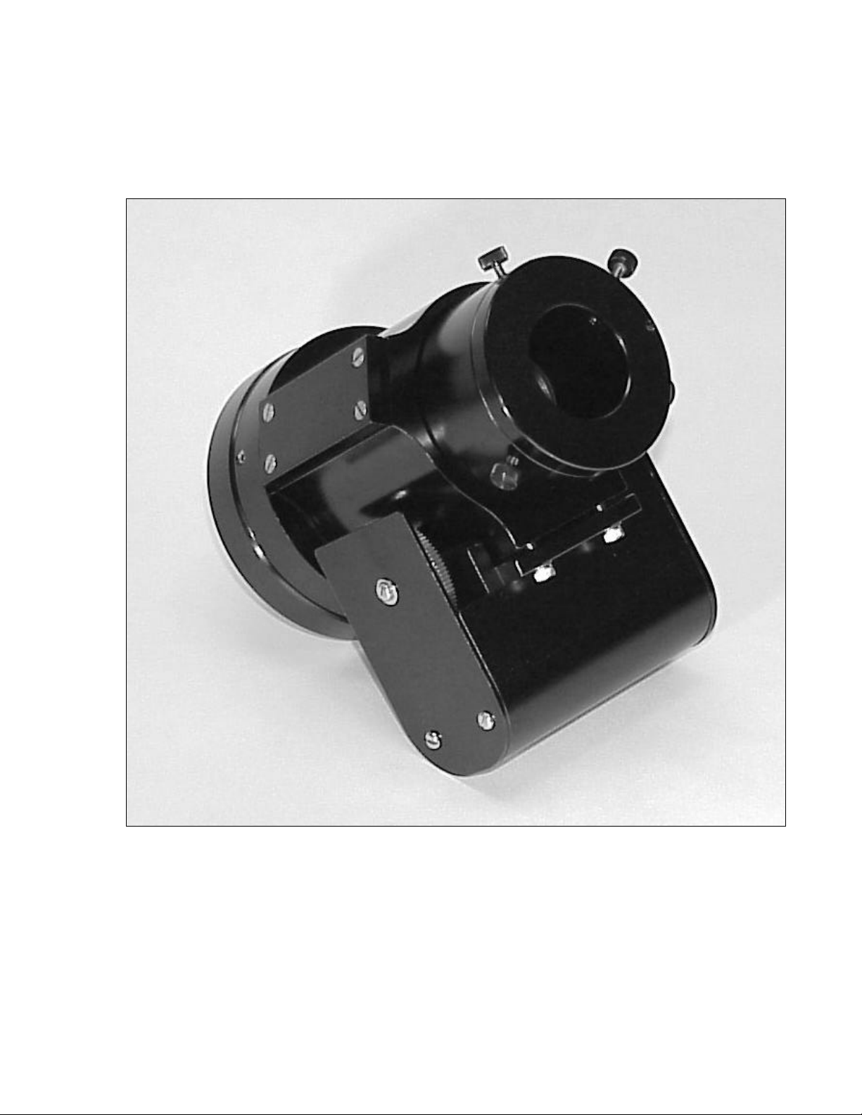
Optec has developed such a system. Mechanically, the new TCF-S (Temperature Compensating
Focuser) is a robust Crayford style motorized focuser with high repeatability. The Crayford
design allows for a solid friction roller focusing system with no play and very little backlash.
Optec’s implementation is ideal for applications that require exact focus such as CCD imaging or
film astrophotography. A geared stepper motor rotates the drive shaft with one step rotation of the
motor equal to a 0.00008-inch movement of the drawtube. A pair of pushbuttons control the
direction of focus and the DRO (digital read-out) displays the current position. The TCF-S
focuser can handle cameras and instrument packages weighing up to 10 pounds.
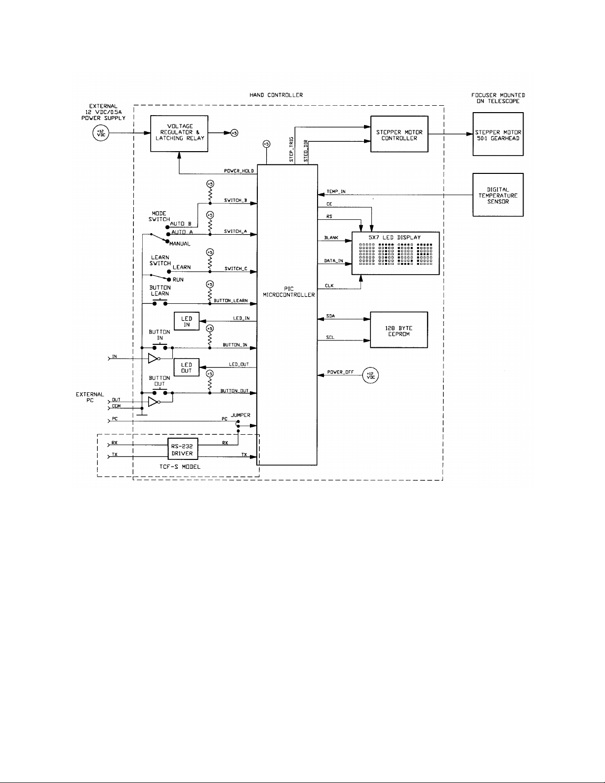
Unique to the TCF-S focuser, an electronic controller system monitors the telescope's tube
temperature and compensates the focus accordingly. A small temperature probe is attached to the
side of the telescope tube and monitors temperature with a resolution of 0.1°C. For a typical
Schmidt-Cassegrain of 8 to 11 inches aperture and f/10 focal ratio, the back focus will move
approximately 0.20 mm for every 1°C change in telescope temperature. It is not unusual during an
observing session for the ambient temperature to change by as much as 10°C within the time span
of a few hours. This change in focus due to temperature is a serious problem for most telescope
designs and requires frequent re-focusing during long exposures. A typical RGB exposure
sequence can last one hour making it imperative that the focus be checked and corrected after each
filter change.
A simple learning procedure is used to find the temperature coefficients specific to the user's
telescope system. The TCF-S system allows for two different coefficients (corresponding to two
different f-ratio configurations) to be calculated and stored in the EEPROM memory. Once
learned, either coefficient can be selected with a simple slide switch. A manual mode allows the
user to set the focus manually at any time.
The digital nature of the TCF-S allows opportunities for truly intelligent focusing. Using a serial
interface, a programmer can control the focuser from any PC. Exact focus can be found by
optimizing a stellar centriod’s diameter.
At the end of an observing session, the TCF-S focuser remembers the last temperature and
position. When the unit is turned back on for a new session, the TCF-S computes a new position
using the current tube temperature and moves to that position. Assuming no changes to the optical
configuration, the object will snap into sharp focus.

2
SECTION 2.0
INSTALLATION
Attach telescope adapter to telescope securely without the TCF-S focuser connected. Back out the
three #8 setscrews around the large diameter so that the TCF-S focuser can slip onto the telescope
adapter. After rotating the TCF-S to the proper position, tighten the three setscrews evenly making
sure no gap is visible between the TCF-Sand the telescope adapter.
If the IFW filter wheel or MAXfilter is used, that item should be attached to the telescope first. An
adapter is available to attach the TCF-S to the IFW or MAXfilter 2”.
Figure 2-1. TCF-S Focuser System Components.
Peel the paper backing off the foam square and use it to secure the temperature probe to the middle
of the telescope tube. Place the temperature probe between the telescope tube and the foam
square. The standard probe length is 20 inches that should accommodate Schmidt-Cassegrain
telescopes from 8 to 12 inches in aperture. Any special length up to 6 feet can be ordered from

3
Optec. The connector tip used on the probe is a mini stereo plug. Connect the temperature probe
plug into the stereo jack on the side of the motor housing.
A control cable with 8-pin modular connector on one end and a 9-pin sub-D connector on the other
is used to connect the TCF-S focuser to the control box. Lengths of cable 6, 12, 25 and 50 feet
long are available from Optec. This is the same cable used with the MAXfilter/IFW and can be
interchanged. IMPORTANT NOTE: Accidentally switching controllers from the TCF and the
MAXfilter/IFW will NOT cause any damage to either unit.
The power supply for the TCF-S is regulated at 12 VDC and 1.25 amp. Use only this type to
power the TCF-S controller. The MAXfilter controller uses a 200 ma power supply that will
overheat when used with the TCF-S. When turning the power off to the TCF-S focuser controller,
use the slide switch first. If the power connector is pulled or power is somehow interrupted to the
unit, the current position and temperature will not be stored. When the unit is powered up again,
the user will have to find a new focus manually.
Figure 2-2. Items Included with TCF-S (stk. #17660) and TCF-S (stk. #17670) Focusers.

4
SECTION 3.0
THEORY OF OPERATION
3.1 CRAYFORD STYLE FOCUSER
The TCF-S focuser uses a classical Crayford design with a 2-inch ID drawtube. The drawtube is
supported within in a sturdy cylinder (main body) by four ball bearing rollers and a stainless steel
drive shaft mounted 120° apart. With a force of 100 to 200 pounds, the drive shaft pushes the
drawtube against the ball bearing rollers, which eliminates all lateral play. Rotating the drive
shaft moves the drawtube through a total distance of 0.6 inches. The drive shaft is supported by
bearings and is made from 303 stainless steel ground to the finished diameter of 0.2497 inches.
The stepper motor with a 50:1 gearhead has a 0.1875-inch diameter drive shaft to which a 25-
tooth spur gear is attached. The main drive shaft is attached to a 96-tooth (quality 10) drive gear.
Thus, the total gear reduction from stepper motor to drive shaft is 192:1. Each step from the motor
moves the drawtube 0.000085 inches. Total backlash of all the gears gives an approximate
longitudinal play of 0.0015 inches (18 steps) as measured with a dial indicator.
Figure 3-1. TCF Cross-Sectional View with Part Descriptions.

5
The motor and drive gears are protected in a motor housing with covers to eliminate any possible
damage to the gear teeth. Drive shaft and stepper motor are all mounted in one machined part to
make sure of the proper gear alignment and maintain rigidity with all loads. The rear of the motor
housing has a 0.1875 diameter ground stainless steel shaft that connects it to the main body and
also allows a small amount of rotation. On the other side of the housing, two #6 cap screws press
the unit with drive shaft against the drawtube with considerable force.
A lightweight 6061 aluminum alloy is used for all machined parts with the exception of the
drawtube. Because of its higher demand for strength and rigidity, the drawtube is made from
6262-T9 alloy, which has almost twice the strength of 6061. All aluminum parts are bright dip and
black anodized for maximum corrosion protection. The drawtube is anodized with a “hard
anodized coat” for increased durability.
See Figure 3-1for sectional views and part descriptions of the focuser assembly.
3.2 FOCUS CONTROLLER
The heart of the controller is the PIC programmable CMOS microcontroller made by Microchip.
This device has 22 I/O pins, 8K of program memory, 192 bytes of RAM and operates at 8 MHz.
Using CMOS technology, this device uses very little power and can operate within the industrial
temperature range specification of -25°C to +80°C. All programming was done in basic and
compiled using PIC Basic Pro by microEngineering Labs of Colorado Springs.
See Figure 3-2for a function diagram view of the TCF-S controller.
The input power source is from a switching DC power unit rated at 12 VDC regulated and 1.25
amp maximum output current. Normally, the TCF-S uses only 230-350 ma when operating. A
three terminal regulator produces +5 VDC for use by the PIC microcontroller, EEPROM, DRO
display and stepper motor controller chips. Using a variety of protection devices, the input power
port is well protected from voltage surges, reverse voltage, low voltage (brownout) and other
circuit busting conditions. A replaceable 5x20 mm fuse rated at 0.5 amps is used for final input
protection. This fuse will blow if the input voltage is reversed which could only happen if the
user incorporates a custom power source such as an automotive battery.
Power is supplied to the TCF-S controller circuits through an SPDT relay of which the coil is
energized by both one pole of the power switch and one of the microcontroller output ports. Thus,
when power is switched off, the microcontroller will sense this condition and will keep the relay
coil energized until the shutdown procedure is completed. The shutdown procedure consists
mainly of writing the current temperature and position to the EEPROM chip, which takes about 0.3
seconds.

6
Figure 3-2. TCF-S Focuser Function Diagram.
An Analog Devices TMP04 serial digital output thermometer is used in the temperature probe.
The modulated signal from this device is processed by the PIC microcontroller and reduced to a
Centigrade scale with 0.1°C resolution. This digital device can operate over an extreme
temperature range and, being digital, produces a very stable output which is unaffected by cable
length and common noise sources.
The DRO uses a premium Hewlett Packard CMOS 5x7 matrix LED display showing four
characters with a height of 0.15 inch. The selection of this device over a lower cost LCD unit is
primarily based on performance. This unit can operate down to -40°C and the LED dot matrix
display is far more visible in low light conditions compared to a LCD device. In addition, the
face of the display is protected by a piece of 1/16-inch thick red acrylic lens, which also enhances
contrast.

7
When the drawtube has moved all the way IN focus toward the telescope, a zero (0) reading is
shown on the DRO display. Movement of the drawtube in the opposite direction or OUT focus
will stop at position 7000, which translates to a total travel distance of 0.60 inches.
An integrated BiMOS unipolar driver chip is used to operate the stepper motor. This device is
rated to operate within the industrial temperature range of -20°C to +85°C and can output a
maximum current of 1.5 Amps far exceeding the needs of the motor. This integrated circuit is fully
protected against inductive transients. In addition, thermal protection circuitry will disable the
outputs when the chip temperature is excessive. This could happen if the output cable is shorted
because of damage or wear.

8
SECTION 4.0
OPERATING PROCEDURES
Refer to Figure 4-1for a view of the hand controller front panel. Tables 4-1 through 4-6 below
explain the six most typical procedures of the TCF-S. Switch settings, functions, and errors are
described.
Figure 4-1. TCF-S Hand Control Layout.

9
START-UP (MANUAL MODE)
SWITCH SETTINGS:
Mode switch is in MANUAL position
Learn switch is in RUN position
FUNCTION:
At the start, the focuser will move all the way IN focus to position 0 (HOME). The DRO will
alternately display the letters TCFS and version number. In addition, both LEDs above the
IN/OUT pushbuttons will be lighted. When at home, the controller will read the last position
before it was shutdown from the EEPROM. The focuser will then go to that position at a rate
of 200 steps/sec.
ERRORS: If the last position read exceeds 7000, the maximum travel length, the TCF-S controller will go
to the mid position or 3500. This could only occur if the EEPROM chip has been replaced or
is defective.
Table 4-1. Start-Up (Manual Mode).
START-UP (AUTO MODE)
SWITCH-SETTINGS:
Mode switch is in AUTO-A or AUTO-B position
Learn switch is in RUN position
FUNCTION:
At the start, the focuser will move all the way IN focus to position 0 (HOME). The DRO will
alternately display the letters TCFS and the version number. In addition, both LEDs above the
IN/OUT pushbuttons will be lighted. When at home, the controller will read the last position
and the last temperature before it was shutdown from the EEPROM. The focuser will then go
to that position taking into account the difference between last temperature and current
temperature.
ERRORS: If the last position read exceeds 7000, the maximum travel length, the TCF controller will go to
the mid-position or 3500. This could only occur if the EEPROM chip has been replaced or is
defective. If the new position computed using the last temperature and current temperature
difference is greater than 7000 or less than 0, the focuser will move to those limits and stop. In
addition, the LEDs above the IN/OUT pushbuttons will flash 4 times.
Table 4-2. Start-Up (Auto Mode).

10
MANUAL FOCUS OPERATION
SWITCH SETTINGS:
Mode switch is in MANUAL position
Learn switch is in RUN position
FUNCTION:
The drawtube is moved in toward the direction of the telescope when the IN pushbutton is
depressed and out toward the camera when the OUT pushbutton is depressed. The LED
above the pushbutton will light up when the associated button is depressed. The current
position is displayed on the DRO. The rate of focus travel is dependent on the duration the
pushbuttons are depressed. A tapping of the pushbuttons will move the drawtube 1 or 2 steps,
about 0.00008 to 0.00016 inches. Holding the pushbuttons down will change the step rate from
6.6 steps/second to a maximum of 200 steps/second. The rate of change is not linear but
geometric.
ERRORS: The travel limits of 0 and 7000 cannot be exceeded. The focuser will stop at those limits and
only travel in the opposite direction is permitted.
Table 4-3. Manual Focus Operation.

11
AUTO FOCUS OPERATION
SWITCH SETTINGS:
Mode switch is in AUTO-A or AUTO-B position
Learn switch is in RUN position
FUNCTION:
Normally, focus is obtained in the MANUAL focus mode. Once achieved, the mode slide
switch is moved to either AUTO-A or AUTO-
B depending on the user's optical configuration.
At that instant, the current position and temperature is read and stored. Every 0.5 seconds a
new temperature is read from the probe and a new position is computed dependent on any
temperature change. The focus is moved to that new position by one step or 0.00008 inches.
This loop is repeated every 0.5 seconds. All calculations are based on the initial temperature
and position so that there is no accumulated error. The LED above either the IN or OUT
pushbuttons, depending on which direction is selected, will flash momentarily indicating the
drawtube has moved one step. While in the auto mode, pressing either the IN or OUT
pushbuttons will have no effect.
ERRORS: The travel limits of 0 and 7000 cannot be exceeded. The focuser will stop at those limits and
the LED above the IN or OUT pushbutton, depending on direction traveled, will flash at a rate
of 2 times per second. The user must return the mode to MANUAL and move the focuser to a
more central position before proceeding with auto focus again. Of course the telescope's main
focusing mechanism will have to be utilized to achieve this coarse focus change.
Table 4-4. Auto Focus Operation.

12
LEARN OPERATION
SWITCH SETTINGS:
Mode switch is in AUTO-A or AUTO-B position
Learn switch is in the LEARN position
FUNCTION:
Step 1. At the start of the LEARN operation the word SET is displayed on the DRO. Using the
IN/OUT pushbuttons, focus as in the MANUAL mode. Once exact focus is obtained with
either eyepiece or CCD camera, press the PROGRAM pushbutton to store initial position and
temperature. After a slight delay, the temperature difference (DT) between initial temperature
and current temperature is displayed on the DRO.
Step 2.
The TCF can now be used as in the MANUAL mode for keeping the object in focus.
However, because of software overhead during this operation there may be a slight delay from
pressing either the IN or OUT pushbuttons and movement of the focuser drawtube. During
movement the current position is displayed on the DRO for a brief time but then returns to
display the temperature difference between initial and current temperature. It is recommended
that a temperature difference of at least 5°C be observed before proceeding with completing
the LEARN operation. The DRO will only display a temperature difference up to 9°C but can
use larger values internally. However, there will only be a slight increase in precision by using
values larger than 9°C. Typically for a 5°C temperature change, a Schmidt-Cassegrain
telescope will show approximately a 600 step change in focus.
Step 3. At any time up to this point the LEARN operation can be aborted and the old values kept by
moving the LEARN slide switch back to the RUN position. After an adequate temperature
change is observed, press the PROGRAM pushbutton and keep it depressed until the word
DONE is displayed on the DRO. At this time, the new temperature coefficient for the selected
AUTO-A or AUTO-B is stored in the EEPROM. The LEARN slide switch must now be
moved to the RUN mode before the unit will operate.
ERRORS:
A temperature difference greater than 16°C during the LEARN operation may cause over-range
errors to occur with unpredictable results. Keep the temperature difference to less than 9°C.
Table 4-5. Learn Operation.

13
SHUTDOWN
SWITCH SETTINGS:
Mode switch in any position
Learn switch in RUN position
FUNCTION:
When the power switch is placed in the OFF position, there is a momentary delay as the
internal PIC microcontroller writes the current position and temperature to the EEPROM.
Once done, the unit will shut down.
ERRORS: The current position and temperature will not be written to the EEPROM if the power is
interrupted or shut down by means other than the ON/OFF power switch. However, the old
values will remain intact.
Table 4-6. Shutdown Procedure.

14
SECTION 5.0
PC SOFTWARE CONTROL
There are now two models of the TCF focuser –the older and out of production TCF temperature
compensating focuser and the newer and improved TCF-S serial version which uses a RS-232
protocol to communicate with an external computer.
5.1 TTL LEVEL CONTROL FOR TCF AND TCF-S
With both the older TCF and the newer TCF-S, the IN and OUT pushbuttons can be operated
remotely through the 6-pin modular interface connector.
This mode of operation uses pins 2, 4 and 5 of the 6-pin modular jack on the TCF or TCF-S
controller. (See Appendix A to locate the pins.) These pins emulate the IN/OUT pushbuttons so
that logic 1 on pin 2 would, in a sense, depress the OUT pushbutton for as long as the port is held
high and a logic 1 on pin 5 would depress the IN pushbutton. Pin 4 is common.
All input signals require TTL voltage levels (0 to +5 volts) and have an input impedance of
approximately 1KW. Debounce circuitry is not needed since it is built into the software that
controls these ports. The ports are normally held low through a 100K resistor so that an open port
condition will not result in erratic behavior. The parallel port from any PC computer should have
no trouble providing these levels. In addition, pins 2 and 5 are protected against overvoltage and
reverse voltage conditions within common limits.
5.2 ADVANCED TTL CONTROL FOR THE TCF
The second mode for the older TCF is designed for advanced programmers only. The mode has
been jumper disabled on the TCF-S to allow for the serial interface. The user should contact
Optec if this mode of control is desired with a model TCF-S knowing that the serial interface will
be disabled. This mode of computer controlled focusing uses pin 3 of the 6-pin modular
connector to send position change information to the TCF focuser. Pins 2 and 5 are used to
determine which direction to move. Like pins 2 and 5, pin 3 requires TTL level signals and is
protected against overvoltage and reverse voltage conditions within common limits.
The method of control is as follows:
1. Initial conditions: pins 2, 3 and 5 are at logic 0.
2. Pin 3 (PC) is brought high.

15
3. Pin 2 (or 5) OUT (or IN) direction pin is brought high.
4. Delay at least 15 ms but not more than 3 seconds. If a delay longer than 3 seconds is
incurred before going to step 5, the device will time out and the OUT LED will flash 10
times before returning to the main routine.
5. Toggle pin 3 (high -low -high) with the duration of the pulse divided by 5µ seconds equal
to the number of steps to be moved.
6. The TCF focuser will move to the new position at 100 steps/second.
7. Bring pins 2, 3 and 5 to a logic 0 before the TCF focuser completes its movement. Note
that each focus step change will require 10 msec to complete.
8. Do not initiate another focus command until the TCF focuser has completed the first
movement. Note that the total time to wait would be the total number of steps to move
times 10 ms.
Pulses up to 0.328 seconds are acceptable but these would exceed the travel limits of the TCF
focuser. It is suggested that pulse widths not exceed 0.01 seconds, which would move the focuser
through 200 steps. Since there is no position feedback to the PC computer, it is up to the
programmer to allow initial position information to be keyed into the program.
5.3 TCF-S -RS-232 SERIAL COMMUNICATIONS
Optec’s Model TCF-S (stock no. 17670) provides an RS-232 serial communications option for the
temperature compensating focuser. The hand controller of the TCF-S includes built-in circuitry
with a full RS-232 driver allowing the user to communicate with the focuser from any external PC.
Using simple ASCII commands this focuser can be moved in or out, set into either of the automatic
modes, or queried for position and temperature. There is even an advanced “Sleep” mode
allowing the user to place the focuser into low power operation remotely. The focuser can then
be restarted remotely at a later time. The Advanced TTL Level Control, described in Section 5.2
above, is superceded by the RS-232 serial interface and is not available with the TCF-S without
removing the on board jumper wire.
5.3.1 CONNECTING THE TCF-S TO THE PC
For the physical wiring connection between the PC and the TCF-S, Optec recommends our PC
serial port converter (stk. #17695) and an RJ-12 reverse cable. Optec offers a number these
cables in lengths from 6-ft to 50-ft. Custom cables can also be ordered. The reverse cable is
wired pin 1 to pin 1, pin 2 to pin 2, etc. A six-wire flat cable with RJ-12 connectors on each end
works well up to at least 120 ft. (Refer to Appendix A for wiring details.)

16
The RS-232 implementation used with the TCF-S is a simple 3-line interface using RX, TX, and
GND. (Refer to Appendix A for wiring details.) At Optec, we use an older DOS shareware
telecommunications program called PROCOMM for focuser control and testing, though any PC
communication program should work. Configured versions of PROCOMM are available for free
download from our FTP site (ftp://ftp.optecinc.com/zip/).
5.3.2 COMMUNICATIONS PROTOCOL
The remote PC communication program should be set for 19.2k-baud rate with 8 data bits, 1 stop
bit, and no parity (8N1). The TCF-S is preset for these values and will not respond to other
settings. Be sure to set the baud rate to 19.2K BAUD before attempting communication with
the TCF-S. Tables 5-1 through 5-11 below describe in detail the commands used to control and
communicate with the TCF-S. To establish communications a Focuser Manual Mode (FMMODE)
command must be sent along the serial line to the focuser. This command should consist of the
ASCII serial string “FMMODE” (without the quotes). If a partial command string is received, the
TCF-S controller will timeout after only a few milliseconds and may not parse the entire command
string properly. The controller program may timeout between characters when sent one at a time.
PROCOMM can be used successfully in the chat or host mode where the string command is not
sent until a CR/LF is typed. Once the FMMODE command has been received and accepted by the
TCF-S, a return character of “!” (followed by a CR/LF) will be sent back to the PC
communications program. None of the other commands will work before the FMMODE command
has properly initialized the serial connection.
Once the serial connection is active, there are commands available to center the focuser, move it in
or out any number of steps, read the current focuser position and temperature, or to set the focuser
into either the A or B automatic modes. Note that serial communications will only occur if the
hand control slide switch is in the Manual position. The Learn slide switch must be in the Run
position. Each command is described separately in the tables below.
The FAMODE and FBMODE commands simulate the Auto-A and Auto-B modes using the same
temperature coefficient values stored in the TCF hand controller memory. While in either of these
automatic modes, all serial input is ignored except for the FMMODE, which returns the
communications, program to manual operation. The LEARN operation for deriving the A and B
mode temperature coefficients is not implemented into the serial routines and must be performed
manually as describe in Section 4.0 (Table 4.5) above.
For the truly remote observatory a special low-power “Sleep” mode is available. The FSLEEP
command will drop the TCF-S into a hibernation mode that simply checks for a wake-up command
(FWAKUP) along the serial line. The remote user can restart the focuser as long as the TCF hand
controller has not lost power. See Tables 5-10 and 5-11 below.
When the communications session is complete, the Focuser Free Command (FFMODE) will
terminate the serial connection. See Table 5-11 below.
Table of contents
Popular Accessories manuals by other brands

oneConcept
oneConcept 10026372 manual

Intelligent Lighting Controls, Inc.
Intelligent Lighting Controls, Inc. WIDEVIEW manual

Aqualytic
Aqualytic TC-Series instruction manual

Green Brook
Green Brook M22W installation instructions

Spring Well
Spring Well SPRW-UV4-2 Operation & installation instructions

TScale
TScale BW Series Technical manual