Throwdown CORE HEALTH & FITNESS ALPHA XTC WR1 User manual

OWNER'S
MANUAL
CORE HEALTH & FITNESS
ALPHA XTC WR1 & WR2

Page 1
TABLE OF CONTENTS
IMPORTANT SAFETY INSTRUCTIONS................................................................................................................2
IMPORTANT LABEL LOCATIONS ........................................................................................................................4
ASSEMBLY ........................................................................................................................6
MAINTENANCE ......................................................................................................................11
TOOLS ................................................................. 11
MAINTENANCE SCHEDULE ................................................................. 12
SUPPORT & SERVICE ......................................................................................................................13
Page 2
Before using this product, it is essential to read the ENTIRE Owner’s Manual and ALL
installation instructions. The Owner’s Manual describes equipment assembly and instructs
members on how to use correctly and safely.
Read all warnings posted on the machine.
Health related injuries may result from incorrect or excessive use of exercise equipment.
Core Health & Fitness strongly recommends you to encourage your members to discuss their
health program or fitness regimen with a health care professional, especially if you or they
have not exercised for several years, are over 35, or have known health conditions.
WARNING!
WARNING: to reduce the risk of serious injury to
persons using this equipment, read and follow all of
these warnings:
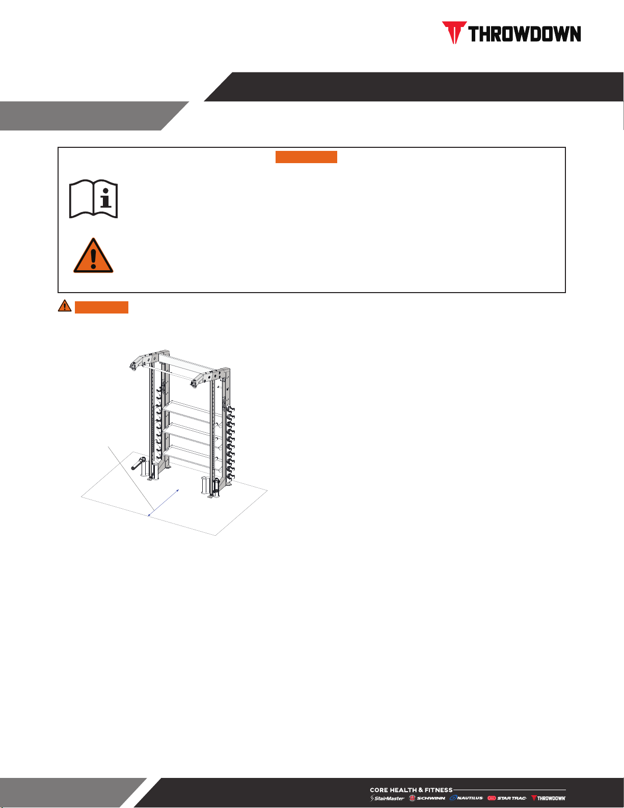
24 in (0.6 m)
Fig. 1 Required Clearance (WR1 Shown)
1. Assemble and operate the unit on a solid level
surface. Position the machine with a minimum of
24 inches (0.6 meters) of clearance on one side
to allow for ease of mounting and dismounting.
Leave a minimum of 19.7 inches (0.5 meters)
between two adjacent units. These dimensions
are the recommended minimum distances.
The actual area for access and passage shall be
the responsibility of the facility and should take
into account this training envelope, Americans
with Disabilities Act Accessibility Guidelines
(ADAAG) requirements and any required local
codes or regulations (www.access-board.gov/
ada).
2. This equipment is designed for use in a
commercial gymnasium or health club. To ensure
the proper use of the equipment in a safe manner,
all users of the equipment should read this
manual before using the machine. This machine
should be made a part of your club training
program in order that the equipment is used by
your members in a safe manner as intended. In
addition to instructing the club members in the
proper use of the equipment, the club member
should obtain a complete physical examination
form their health care provider before beginning
any exercise program.
3. The safety and integrity of this machine can only
be maintained when the equipment is regularly
examined for damage and wear and repaired.
It is the sole responsibility of the owner of this
equipment to ensure that regular maintenance
is performed. Worn or damaged parts must be
replaced immediately or the equipment removed
from service until the repair is made.
4. Use only replacement components supplied by
Throwdown. Substitutes are forbidden and will
void all warranties.
5. This machine is not intended to be used by
persons with reduced physical, sensory, or
mental capabilities or lack of experience and
knowledge, unless given instruction and under
the personal supervision concerning use of the
machine by a person responsible for their safety.
6. Keep children away.
7. Wear proper exercise clothing and athletic shoes
during a workout. Avoid wearing loose clothing.
Tie back long hair and keep towels away from the
moving parts.
IMPORTANT SAFETY INSTRUCTIONS

Page 3
8. Do not over exert yourself during exercise. Stop
exercising if you feel pain or tightness in your
chest, become short of breath or feel faint. If you
feel pain or experience any abnormal symptoms,
stop exercising and consult your health care
provider.
9. It is the purchaser’s sole responsibility to properly
instruct its end users and supervising personnel
as to the proper operating procedures of all
Throwdown equipment.
SAVE THESE INSTRUCTIONS
Page 4
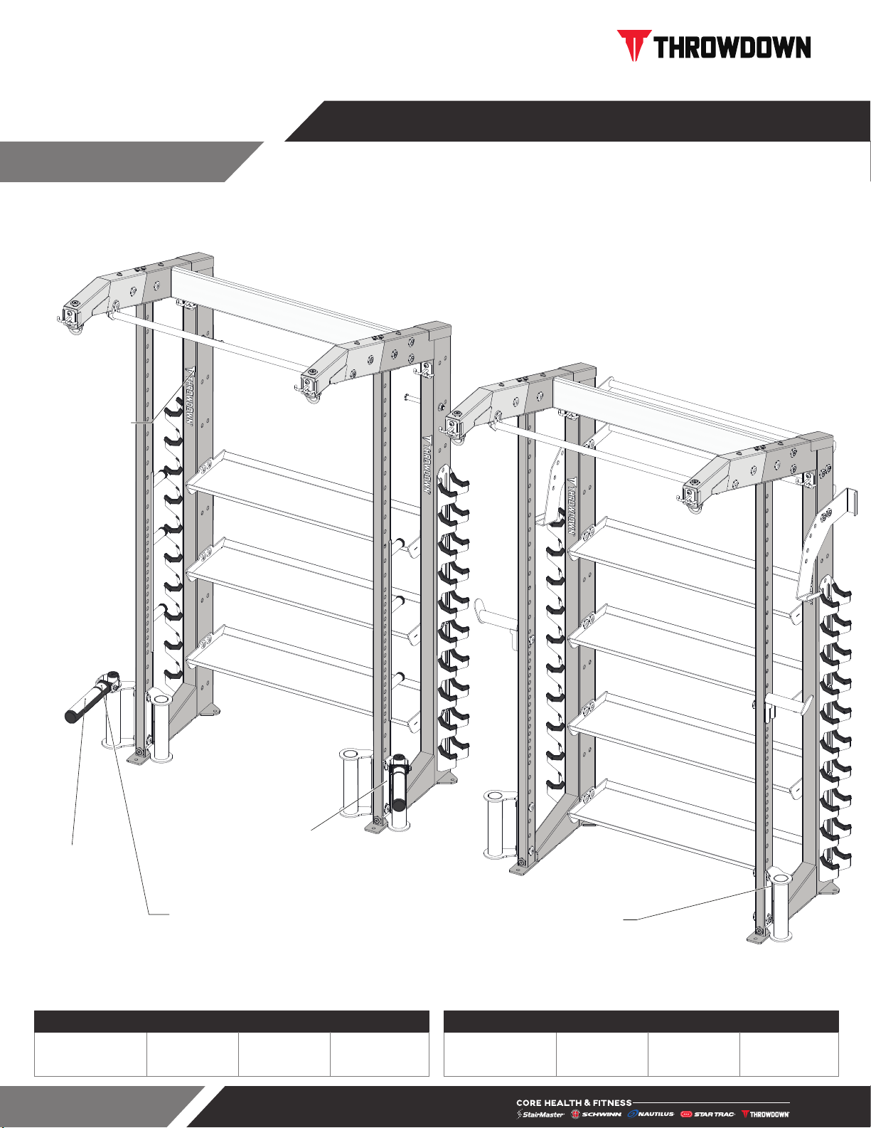
This page shows the location of the warning labels and communication stickers placed on the equipment as part of the manufacturing process. It is critical that
owners maintain the integrity and placement of these stickers. If you find any stickers missing or damaged the replacement numbers are shown on the support
site and following pages. See Support and Service to order replacements.
12-00212
81-00016
81-00005
Serial Label
Serial Label
Fig. 2
IMPORTANT LABEL LOCATIONS
SKU: TD-WR1-XXXXX Desc: Weight Room 1 SKU: TD-WR2-XXXXX Desc: Weight Room 2
Unit Weight Width Length Height
642 lbs
291 kg
69.6 in
177 cm
54.6 in
138 cm
105.5 in
268 cm
Unit Weight Width Length Height
595 lbs
270 kg
68.9 in
175 cm
56.7 in
144 cm
105.5 in
268 cm

Page 5
81-00005
THROWDOWN VERTICAL LOGO
81-00016
STICKER,WARNING,LANDMINE
12-00212
STICKER, PINCH POINT
Notice: images are not to scale
Page 6
All equipment MUST be secured
(bolted and tightened) to a solid, level
surface, using all of the anchoring
holes provided, to stabilize and
eliminate rocking or tipping over. Shim
any mounting surface that does not
rest thoroughly on the floor using flat
washers, DO NOT force the foot to
contact the ground with anchors.
Fasteners must have a minimum of 500 lbs. tensile capacity, be a bolt of grade 2 or better and be installed per
the bolt manufacturer’s specifications.
Due to the wide variety of flooring on which equipment may be anchored or installed and differences in
applicable local building codes, Core Health & Fitness is not responsible for any damage to the flooring that
may result due to anchoring or installing equipment to the floor and for compliance with local building codes.
Only licensed contractors or certified installers should be used to insure proper anchoring, installation, and
compliance with local building code.
Required Tools:
• Metric Allen Key Set
• Loctite Blue1
• Torque Wrench
• Metric Open-Ended Wrench Set
• Large Adjustable Crescent Wrench
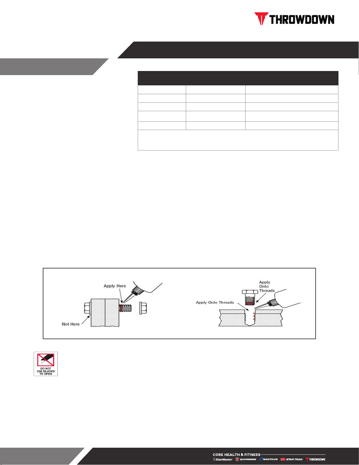
THREAD LOCKER APPLICATION: Clean all threads and holes, apply no more than 3-4 drops per bolt.
Thru Holes Blind Holes
PACKAGING REMOVAL:
Unit is heavy and requires two people for assembly.
Carefully remove all packaging materials that wrap the equipment.
DO NOT USE A KNIFE OR BOX CUTTER AS YOU MAY DAMAGE THE EQUIPMENT.
At this time remove any sub-components from the pallet and set aside for later assembly. Once all packaging
has been removed, lay all parts out in a clean open area to prepare for assembly. Should any component not
be present or if you have any operational questions, please refer to SUPPORT & SERVICE
After assembly, a complete visual inspection, and test of the features and functions of the assembled unit must
be made prior to use.
ASSEMBLY
Metric Steel Bolts Torque Specifications
Bolt Size Thread Pitch Torque, N-m (lbs-ft)
6mm 1.25 10 to13.5 (8 to10)
8mm 1.25 25.5 to 28.5 (19 to 21)
10mm 1.75 55.5 to 58 (41 to 43)
12mm 1.25 61 to 65 (45 to 48)
• Torque all hardware to values as specified above, unless noted otherwise.
• See procedure of this manual for fastener sizing information; for reference only.
Note: All torque values are in N-m unless otherwise stated.

Page 7
TD-WR1 PROCEDURE
1. Slide the rack side upper hanger
assemblies 73-00161-XX onto the
two side frames then secure with
one bolt set in the side, and two of
the M12x1.75,30mm bolts (31-
00392) and two washers 31-00267
top and bottom.
Note: Many accessories and
supports are attached with large
bolt sets consisting of one each
M12 x 90 Flat Head Bolt (31-
00396), a bolt washer (11-00811)
and a bolt nut (11-00810).
11-00810
11-00811
31-00396
73-00161-XX
31-00267
31-00392
Fig. 3
2. Prior to standing frames up attach
the shelving and the vertical
dumbell racks to the frame in
using six large bolt sets per side.
3. Attach the upper stabilizer to
the frames with two large bolt sets
per side.
4. Stand frame up and fully tighten all
hardware.
Fig. 4

Page 8
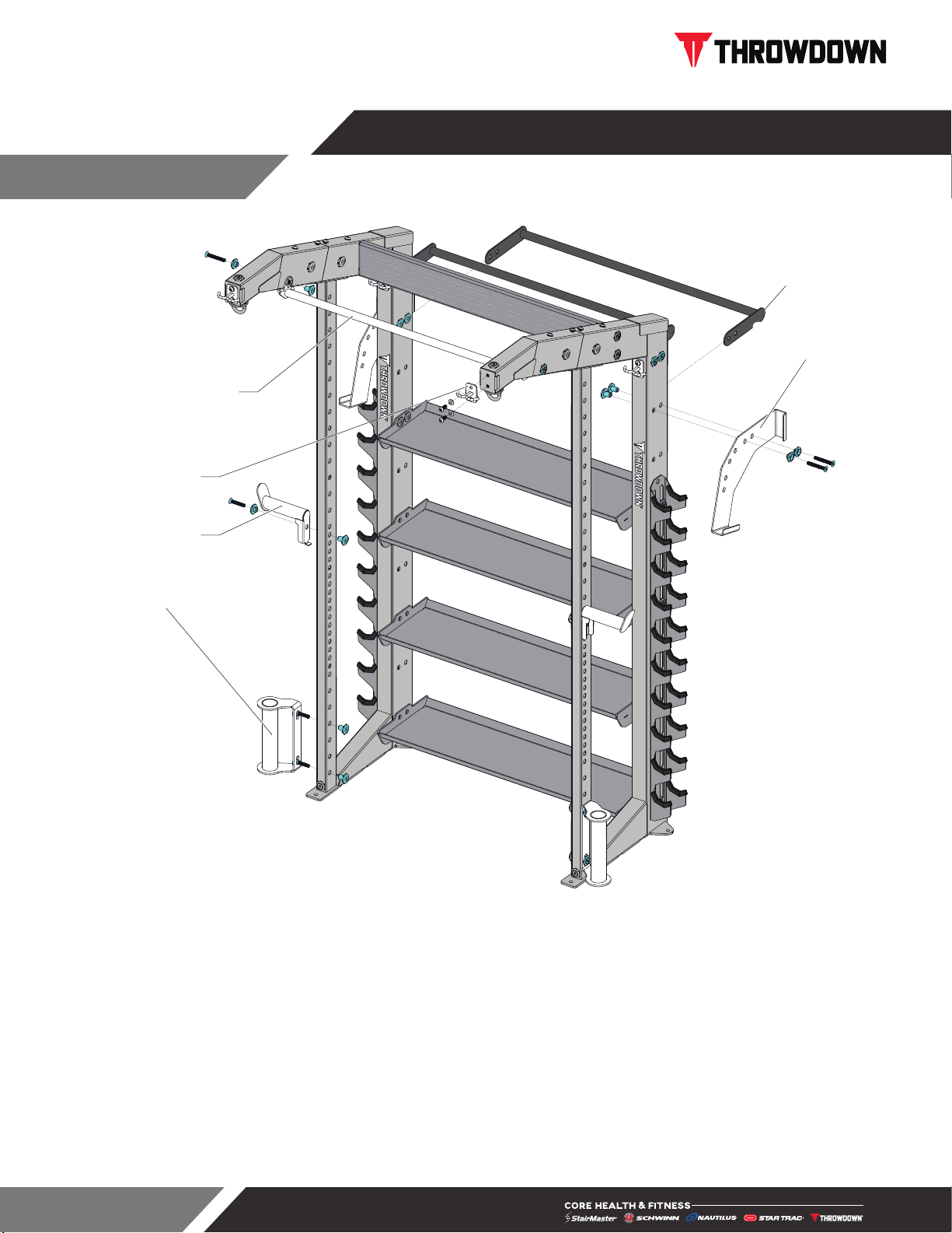
71-00267-XX
73-00163
73-00162
73-00164-XX
52-00260-XX
52-00261
Fig. 5
5. Attach pull-up bar assembly (52-00260-XX) at top of unit using one large bolt set per side.
6. Attach all 4 Double-J hooks (52-00261) to the frame using two M12x1.75,30mm bolts (31-00392) and
washers 31-00267 each.
7. Attach the weight plate storage hangars (73-00162) using three M12x1.75,30mm bolts (31-00392) and
washers 31-00267 each.
8. Install the Oly Bar kits (71-00267-XX) at the bottom of the unit with two large bolt sets each. The Landmine
accessory (73-00163) goes into the Oly Bar kits.
9. Fully tighten all hardware.
10. Assembly is complete.

Page 9
TD-WR2 PROCEDURE
1. Slide the rack side upper hanger
assemblies 73-00161-XX onto the
two side frames then secure with
one bolt set in the side, and two of
the M12x1.75,30mm bolts (31-
00392) and two washers 31-00267
top and bottom.
Note: Many accessories and
supports are attached with large
bolt sets consisting of one each
M12 x 90 Flat Head Bolt (31-
00396), a bolt washer (11-00811)
and a bolt nut (11-00810).
11-00810
11-00811
31-00396
73-00161-XX
31-00267
31-00392
Fig. 6
2. Prior to standing frames up attach
the shelving and the vertical
dumbell racks to the frame
using eight large bolt sets per
side.
3. Attach the upper stabilizer to
the frames with two large bolt sets
per side.
4. Stand frame up and fully tighten all
hardware.
Fig. 7
Page 10
71-00267-XX
52-00267
52-00268-XX
12-00313
52-00260-XX
52-00261
Fig. 8
5. Install the two bars (52-00268-XX) at the top of the unit using two large bolt sets per side. The lower bar is
installed with the balance ball storages (12-00313) on the outside of the frame on either side.
6. Attach pull-up bar assembly (52-00260-XX) at top of unit using a large bolt set on each side.
7. Attach all 4 Double-J hooks (52-00261) to the frame using two M12x1.75,30mm bolts (31-00392) and two
washers 31-00267 each.
8. Install the Oly Bar kits (71-00267-XX) at the bottom of the unit with two large bolt sets each.
9. Attach the Rope Hangar pegs (52-00267) to the left and right of the unit with a large bolt set.
10. Fully tighten all hardware.
11. Assembly is complete.

Page 11
TOOLS
Working on this product will require basic and/or sometimes specialty tools based on the type of service that
will be performed at any time. To assist, we recommend having the tools listed available when performing
maintenance.
Tool
Socket Set, Metric Screwdriver Set, Flat
8mm Hex Bit Rubber Mallet or Dead-Blow Hammer
Socket driver Tape Measure
Open end wrenches, Metric Motorcycle straps, adjustable
Hex Bit Socket Set, SAE Loctite 243
Adjustable Wrench Chalk Line
Torque Wrench
MAINTAIN ALL EQUIPMENT: Preventative maintenance is the key to smooth operating equipment as well
as keeping the product in safe operating condition. Failure to conduct preventative maintenance by the owner
may cause the product to operate in an unsafe manner. Equipment needs to be inspected and maintained at
regular intervals per the preventative maintenance schedule provided in this manual.
Cleaning
Keeping your Strength units clean is an important component of preventative maintenance and the overall
aesthetics of your product. While your clients will appreciate clean equipment free of sweat, dirt and other
contaminants proper care and cleaning will extend the life of your product and reduce premature aging and
wear. See the maintenance schedule for recommended frequency.
Inspection
Visual inspection of your units will insure a safe environment for your clients and alert you to any issues that
may require maintenance prior to equipment failure. Proper, timely visual inspection is a critical component to
the long term care of your product.
• Fasteners, hardware and attachments should be checked monthly for looseness. Tighten as required
using appropriate tools.
• Main frame should be inspected every six months for signs of unusual wear, corrosion or structural
integrity issues.
MAINTENANCE

Page 12
MAINTENANCE SCHEDULE
With durable, high performance components, this equipment is designed for heavy usage with minimal
maintenance required. To keep it in top condition, perform regular daily, weekly and monthly preventive
maintenance routines outlined below.
The safety and integrity of this machine can only be maintained when the equipment is regularly examined for
damage and wear and repaired. It is the sole responsibility of the owner of this equipment to ensure that regular
maintenance is performed. Worn or damaged parts must be replaced immediately or the equipment removed
from service until the repair is made.
Daily Weekly Monthly Bi-Annually
Inspect
Check Safety & Warning Labels X
Check for loose bolts & hardware X
Cleaning
Main Frame1X
1 Clean with a water dampened cloth & wipe dry after cleaning.

Page 13
SUPPORT & SERVICE
For Technical Support, Service, Parts Orders or any Customer Service needs, please contact us direct by phone,
email, or through our 24 hour support site:
To help us support you, please provide the following information when requesting assistance with your equipment:
Facility Name & Address Product Serial Number Description of Issue
Our goal is to provide fast, reliable support to all your product support requests. We strive to answer all support
requests under an average hold time of 3 minutes, all support emails within 1 business day and all field service
requests within 48 hours.
PREVENTATIVE MAINTENANCE
Protect your product & assure it always runs like new with a Core Advantage Preventative Maintenance or Extended
To request access scan or visit:
CONNECT.COREHANDF.COM
• General Inquiries
• Warranty Registration
• Preventative Maintenance
• Service Requests
• Parts Orders
• Automated partner payment
• Product technical library
• Transparency on service performance
• 24-Hour Automated Assistant
• Live Chat
OFFERS 24-HOUR SELF SERVICE ACCESS TO:
Core Connect is your portal to all things service! Whether you need to
order parts or register your warranty, Core Connect is the most effective
way to get what you need fast and keep your facility operating smoothly.
CORE CONNECT
GLOBAL SUPPORT CENTER
4400 NE 77th Avenue, Suite 300 Vancouver, WA 98662
Warranty information: https://corehandf.com/warranty
Core Connect is accessible through our app on mobile devices

Page 14
THIS PAGE INTENTIONALLY BLANK

© 2021 CORE HEALTH & FITNESS LLC PART NUMBER 90-00060, REV A
All rights reserved. Star Trac, the Star Trac logo and StairMaster are registered trademarks of Core Health & Fitness, LLC. Schwinn and Nautilus are registered
trademarks of Nautilus Inc. used under license to Core Health & Fitness LLC. Throwdown is a registered trademark of Throwdown Industries, LLC.
This manual suits for next models
1
Table of contents
Other Throwdown Fitness Equipment manuals


