TICA TIMS080AS User manual

1
CONTENTS
SAFETY PRECAUTIONS................................................................................3
Cautions and Warnings .................................................................................3
WARNINGS DURING REPAIR........................................................................3
PREFACE........................................................................................................6
CHAPTER I OVERVIEW .................................................................................7
1. Models ........................................................................................................7
2. Nomenclature ...........................................................................................12
CHAPTER II SYSTEM PRINCIPLE...............................................................14
1. Refrigerating System Schematic Diagram.............................................14
2. Exploded view/3D diagram......................................................................20
3. Refrigerant Flow Direction in Different Operating Modes ....................33
CHAPTER 4 BASIC CONTROL....................................................................36
1. Basic Control............................................................................................36
2. Protection Control ...................................................................................37
4. IDU Control ...............................................................................................45
CHAPTER V TESTING AND TRIAL OPERATION........................................58
1. Testing before Operation.........................................................................58
2. Testing Software ......................................................................................62
3. Centralized Control..................................................................................66
4. Household-based Charging ....................................................................74

2
CHAPTER VI TROUBLESHOOTING............................................................92
1. Fault Code List .........................................................................................92
2. Common fault handling and analysis ..................................................102
CHAPTER VII ELECTRICAL CONCEPTUAL DIAGRAM AND
DESCRIPTION OF DIP SWITCH ................................................................152
1. IDU and ODU DIP Switch Table.............................................................152
2. Electric control system .........................................................................159
CHAPTER VIII APPENDIXES .....................................................................169

3
Safety Precautions
Cautions and Warnings
Read these precautions carefully before repair.
This manual classifies the precautions into Warning and Caution. Warning is very
important as failure to observe it may lead to deaths or serious injuries. Caution is also
important as in some cases failure to observe it may also lead to grave accidents. Hence,
be sure to follow the safety precautions below.
After completing repair, test the unit to ensure it runs properly. In addition, give the
user adequate instructions concerning the precautions when using this unit.
Warnings During Repair
Before dismantling the unit for repair, be sure to remove the power plug, as operating
a device that is powered on may result in electric shock. If repair must be carried out
with power on, do not touch any active part.
Keep away from the refrigerant gas that leaks during repair, because exposure to this
gas may result in frostbite.
When dismantling compressor intake or discharge pipes at welding part, first empty
refrigerant gas in a well-ventilated place, as the trapped refrigerant gas or refrigerator
oil may flow out and cause injuries.
If any refrigerant gas leaks during repair, ventilate the place immediately. Refrigerant
gas may produce a toxic gas if it comes in contact with fire.
Boost capacitor is a component that provides high voltage electricity for ODU
electrical parts. Make sure it is fully discharged before repair; otherwise, it may cause
electric shock.
Do not attempt to turn on or off the unit by inserting or removing the power plug, as
this may result in electric shock or fire.
Precautions During Repair
Do not attempt to touch electrical parts with wet hands, as it may cause electric shock.
Do not clean the air conditioner by spraying water on it, as it may cause electric
shock.
To prevent an electric shock, make sure that the unit is grounded when repair is
carried out in a damp place.
Cut off the power supply and remove the power plug before cleaning.
The fan running at high speed may hurt people.
When relocating the unit, do not tilt it; otherwise, the water inside the unit may splash
on floor and furniture.

4
Before repair, check to make sure that the refrigeration and circulation system is fully
cooled. Otherwise, it may result in burns.
Make sure to use the gas welding machine in a well-ventilated place, as use of it in a
sealed room may cause hypoxia.
Warnings after Repair
Use components listed in the Maintenance Parts List and appropriate tools of the
corresponding model. Do not attempt to modify the unit, as improper use of
components or tools may cause electric shock, overheating or fire.
When installing the unit in a new place, make sure that the place of installation is
strong enough to support the unit’s weight. If the place cannot provide enough
support or the installation is not secure enough, the unit may fall and cause injuries.
Make sure to use a standard mounting rack to install the unit. Improper use of
mounting rack or operations may result in unit dropping and personal injuries.
Fasten the unit securely to the mounting rack that is fixed on the sash frame.
Improper installations may cause unit falling and personal injuries.
When wiring, make sure to use a dedicated power supply and observe the relevant
technical standards, internal wiring rules and installation manual on electrical equipment.
Insufficient power capacity and improper electrical wiring may cause electric shock or fire.
Be sure to use dedicated cables to connect IDU and ODU. Fasten and arrange the
wires in a way that the wires at the joint are not too tight. Improper wiring may result in
overheating or fire.
When connecting IDU and ODU, make sure that the terminal cover doesn't fall off
because cables extend out of the cover. If the covers are improperly fixed, the
terminal connection part may cause electric shock, overheating or fire.
Do not damage or change power cords, as damaged or changed power cords may
result in electric shock or fire.
Do not put heavy objects on power cords. Heating or stretching power cords will
cause damages to power cords.
Use designated refrigerants (R-410A) in the refrigerating system. Do not let air or
other gases in refrigerating system, as it may generate high pressure and hence
damage the unit.
If refrigerant gas leaks, make sure to find the leaking points and repair them before
refrigerant can be added. If leaking points cannot be determined, stop repair work
immediately and perform evacuation. Close service valves to prevent refrigerant gas
from entering the room. Refrigerant gas is nontoxic in itself. However, when it comes
in contact with fire, or fans, other heaters, furnaces, it may generate toxic gases.

5
Make sure to dispose of the old batteries after removing them from the remote
controller. Keep these batteries away from children.
Precautions after Repair
Residual current device may be provided depending on circumstances to prevent
electric shock.
Do not install the unit where flammable gases are present, as it may cause fire.
Install sealing parts and pads to mounting rack correctly, as improper installations
may let water in room and wet furniture and floor.
Check after Repair
Check to make sure that power plug is clean and fastened securely, and then insert
the power plug into power socket. If power plug is dirty or loosened, electric shock or
fire may occur.
If cables and wires are scratched or damaged, make sure to replace them with new
ones, as broken cables or wires may cause electric shock, overheating or fire.
Do not use cables in tandem or stretched cables. Use a separate socket. Otherwise,
it may cause electric shock, overheating or fire.
Check whether all parts are fastened reliably, wires connected correctly and welding
part or crimping part connected securely. Improper installation or wiring may result in
electric shock, overheating or fire.
Replace the corroded mounting stand or rack with a new one, as the old ones may fall
off and cause personal injuries.
Check grounding. If the unit is grounded improperly, repair it immediately, as improper
grounding may cause electric shock.
After repair, measure insulation resistance to make sure that the value is at least
1 MΩ, as improper insulation may cause electric shock.
After repair, check IDU drainage status, as improper drainage may allow water enter
the room and wet the floor or furniture in it.

6
Preface
Thank you for purchasing TICA products.
This is the Maintenance Manual for TICA cooling and heating type air conditioners (TIMS).
TICA offers a broad spectrum of models to meet different air conditioning needs in
buildings and offices. We believe that there is a model for everyone.
This Maintenance Manual contains information on repairing R-410A cooling and heating
type air conditioner (TIMS).
December 2016
TICA Technology Center

7
Chapter I Overview
1. Models
1. Models and Codes of VRF ODUs
Product series Product model Batch No. Remarks
Individual
VRF ODU
TIMS**AS
TIMS080AS P70432000000
8-16HP Single
compressor Full inverter
18-32HP Dual
compressor Full inverter
TIMS100AS P70433000000
TIMS120AS P70389000000
TIMS140AS P70350000000
TIMS160AS P70351000000
TIMS180AS P70379000000
TIMS200AS P70272000000
TIMS220AS P70380000000
TIMS240AS P70381000000
TIMS260AS P70440000000
TIMS280AS P70536000000
TIMS300AS P70537000000
TIMS320AS P70538000000
Full inverter
VRF ODU
TIMS**AX
TIMS080AX P70526000000
Full inverter 3 modules in
parallel allowable
TIMS100AX P70527000000
TIMS120AX P70528000000
TIMS140AX P70515000000
TIMS160AX P70444000000
TIMS180AX P70524000000
TIMS200AX P70525000000
TIMS220AX P70505000000
Strong-heat
individual
VRF ODU
TIMS**AST
TIMS080AST P70849000000
8-18HP Single
compressor Full inverter
EVI
TIMS100AST P70850000000
TIMS120AST P70851000000
TIMS140AST P70852000000
TIMS160AST P70853000000
TIMS180AST P70854000000

8
2. Models and Codes of VRF IDUs
Product
series Product model Batch No. Remarks
All-way
embedded
IDU
TMCF028AB P70245000000
TMCF036AB P70246000000
TMCF045AB P70363000000
TMCF050AB P70547000000
TMCF056AB P70247000000
TMCF063AB P70548000000
TMCF071AB P70377000000
TMCF080AB P70248000000
TMCF090AB P70361000000
TMCF100AB P70249000000
TMCF112AB P70362000000
TMCF125AB P70250000000
TMCF140AB P70360000000
TMCF160AB P70549000000
Two-way
embedded
IDU
TMCD028A P70131000000
TMCD036A P70132000000
TMCD045A P70133000000
TMCD056A P70134000000
TMCD071A P70135000000
TMCD080A P70136000000
TMCD090A P70137000000
TMCD100A P70138000000
TMCD112A P70139000000
TMCD125A P70140000000
TMCD140A P70141000000
One-way
embedded
IDU
TMCS028A P70142000000
TMCS036A P70143000000
TMCS045A P70144000000
TMCS056A P70145000000
TMCS071A P70146000000
Ultra-thin
silent duct
type IDU
TMDN022AC P70517000000
TMDN025AC P70518000000
TMDN028AC P70481000000
TMDN032AC P70519000000
TMDN036AC P70445000000
TMDN040AC P70520000000
TMDN045AC P70521000000
TMDN050AC P70466000000
TMDN056AC P70522000000
TMDN063AC P70523000000

9
Product
series Product model Batch No. Remarks
TMDN071AC P70478000000
TMDN022AC-NS P70770000000
TMDN025AC-NS P70771000000
TMDN028AC-NS P70772000000
TMDN032AC-NS P70773000000
TMDN036AC-NS P70774000000
TMDN040AC-NS P70775000000
TMDN045AC-NS P70776000000
TMDN050AC-NS P70777000000
TMDN056AC-NS P70778000000
TMDN063AC-NS P70779000000
TMDN071AC-NS P70780000000
Standard duct
type IDU
TMDN022AB P70276000000
TMDN025AB P70277000000
TMDN028AB P70278000000
TMDN032AB P70279000000
TMDN036AB P70280000000
TMDN040AB P70281000000
TMDN045AB P70282000000
TMDN050AB P70283000000
TMDN056AB P70284000000
TMDN063AB P70285000000
TMDN071AB P70286000000
TMDN080AB P70287000000
TMDN090AB P70288000000
TMDN100AB P70289000000
TMDN112AB P70290000000
TMDN125AB P70343000000
TMDN140AB P70342000000
TMDN160AB P70800000000
TMDN080AB-NS P70764000000
TMDN090AB-NS P70765000000
TMDN100AB-NS P70766000000
TMDN112AB-NS P70767000000
TMDN125AB-NS P70768000000
TMDN140AB-NS P70769000000
High static
pressure duct
type IDU
TMDH100A P70170000000
TMDH112A P70171000000
TMDH125A P70172000000
TMDH140A P70173000000

10
High-capacity
duct type IDU
TMDH195AI P70669000000
TMDH255AI P70670000000
TMDH410AI P70685000000
TMDH520AI P70846000000
TMDH620AI P70847000000
TMDH790AI P70848000000
Ceiling
exposed/floor
type IDU
TMVX028A P70162000000
TMVX036A P70163000000
TMVX056A P70164000000
TMVX071A P70165000000
TMVX090A P70166000000
TMVX112A P70167000000
TMVX125A P70168000000
TMVX140A P70169000000
Wall mounted
IDU
TMVW028A P70158000000
TMVW036A P70159000000
TMVW040A P70550000000
TMVW056A P70160000000
TMVW063A P70551000000
TMVW071A P70161000000
Full-fresh air
handling unit
TMDF175A-022 P70174000000
TMDF210A-020 P70175000000
TMDF250A-015 P70176000000
TMDF250A-020 P70177000000
TMDF250A-030 P70178000000
TMDF300A-020 P70179000000
TMDF400A-020 P70180000000
TMDF400A-030 P70181000000
TMDF500A-020 P70182000000
TMDF500A-030 P70183000000
TMDF600A-020 P70184000000
TMDF600A-030 P70185000000
Series E
ultra-thin duct
type IDU
TMDS022AE P70492000000
TMDS025AE P70493000000
TMDS028AE P70494000000
TMDS032AE P70495000000
TMDS036AE P70496000000
TMDS040AE P70497000000
TMDS046AE P70498000000
TMDS050AE P70499000000
TMDS056AE P70500000000
TMDS063AE P70501000000

11
TMDS071AE P70502000000
Series D DC
ultra-thin duct
type IDU
TMDS022AD P70579000000
TMDS025AD P70580000000
TMDS028AD P70581000000
TMDS032AD P70582000000
TMDS036AD P70583000000
TMDS040AD P70584000000
TMDS046AD P70585000000
TMDS050AD P70586000000
TMDS056AD P70587000000
TMDS063AD P70588000000
Series E
four-way
embedded
IDU
TMCF036AE P70594000000
TMCF040AE P70595000000
TMCF046AE P70596000000
TMCF050AE P70597000000
TMCF056AE P70598000000
Mini quiet
series
ventilators
TRD015ACA V4A14D000000
TRD020ACA V4A14F000000
TRD030ACA V4A14H000000
TRD040ACA V4A14K000000
TRD060ACA V4A14M000000
TRD080ACA V4A14P000000
TRD015ACC V4A14E000000
TRD020ACC V4A14G000000
TRD030ACC V4A14J000000
TRD040ACC V4A14L000000
TRD060ACC V4A14N000000
TRD080ACC V4A14Q000000
Medium
high-end
series fresh
air ventilators
TRD100ACB V4A0XF000000
TRD150ACB V4A0ZZ000000
TRD200ACB V4A0YM000000
TRD250ACB V4A0YL000000
TRD300ACB V4A0ZE000000
TRD400ACB V4A10G000000
TRD500ACB V4A10H000000
TRD600ACB V4A10J000000
Notes: The foregoing models are expected to go on the market in 2016. However, they
are subject to change over time; please refer to listing or change notice for specific models
and their functions.

12
2. Nomenclature
2.1 ODUs
TIMS 080 A A
1~4 5~7 8 9
Digits 1-4: TICA inverter VRF air conditioning unit (ODU)
Digits 5-7: Specifications
For example: 080 = 8HP
Digit 8: Design S/N
A
The 9: Structure
S: Individual X: Full inverter ST: Strong-heat individual
2.2 IDUs
TM C S 028 A A
1~2 3 4 5~7 8 9
Digits 1-2: TICA inverter VRF air conditioning unit (IDU)
Digit 3: IDU type
C: Embedded type D: Duct type V: Exposed type
Digit 4: Classification of types
S: Ceiling embedded (C type) S: Ultra-thin duct type (D type)
D: Two-way embedded (C type) N: Standard duct type (D type)
F: Four-way embedded (C type) H: High static pressure duct type (D type)
W: Wall-mounted (V type) F: All fresh air duct type (D type)
X: Ceiling exposed/floor type (V type)
Digits 5-7: Specifications
028: 2.8 kW
175: 1750CMH (only applied to TMDF)
Digit 8: Design S/N
A
Digit 9: Product code Standard configuration May be omitted
2.3 Branch pipes
TVB 16 A 2
1-3 4-5 6 7
Digits 1-3
TICA flow control box

13
Digits 4-5
Specifications
16 applied to 2.2kW~3.6kW
18 applied to 4.0kW~5.6kW
20 applied to 6.3kW~9.0kW
25 applied to 10.0kW~14.0kW
Digit 6
Design S/N
A
Digit 7
Pipe diameter
2=1/4"
3=3/8"
2.4 AHU kits
TBP 4022T A
1-3 4-8 9
Digits 1-3
TICA branch pipes
Digits 4-8
Specifications
4022T
R410a: IDU total capacity < 22.5 kW
4033T
R410a: 22.5 kW ≤IDU total capacity < 35.0 kW
4072T
R410a: 35.0 kW ≤IDU total capacity < 71.0 kW
4073T
R410a: IDU total capacity > 71.0 kW
4073P
Used together with 4073T
4090T
R410a: Dual module connection pipe
4135T
R410a: Triple module connection pipe
Digit 9
Design S/N

14
Chapter II System Principle
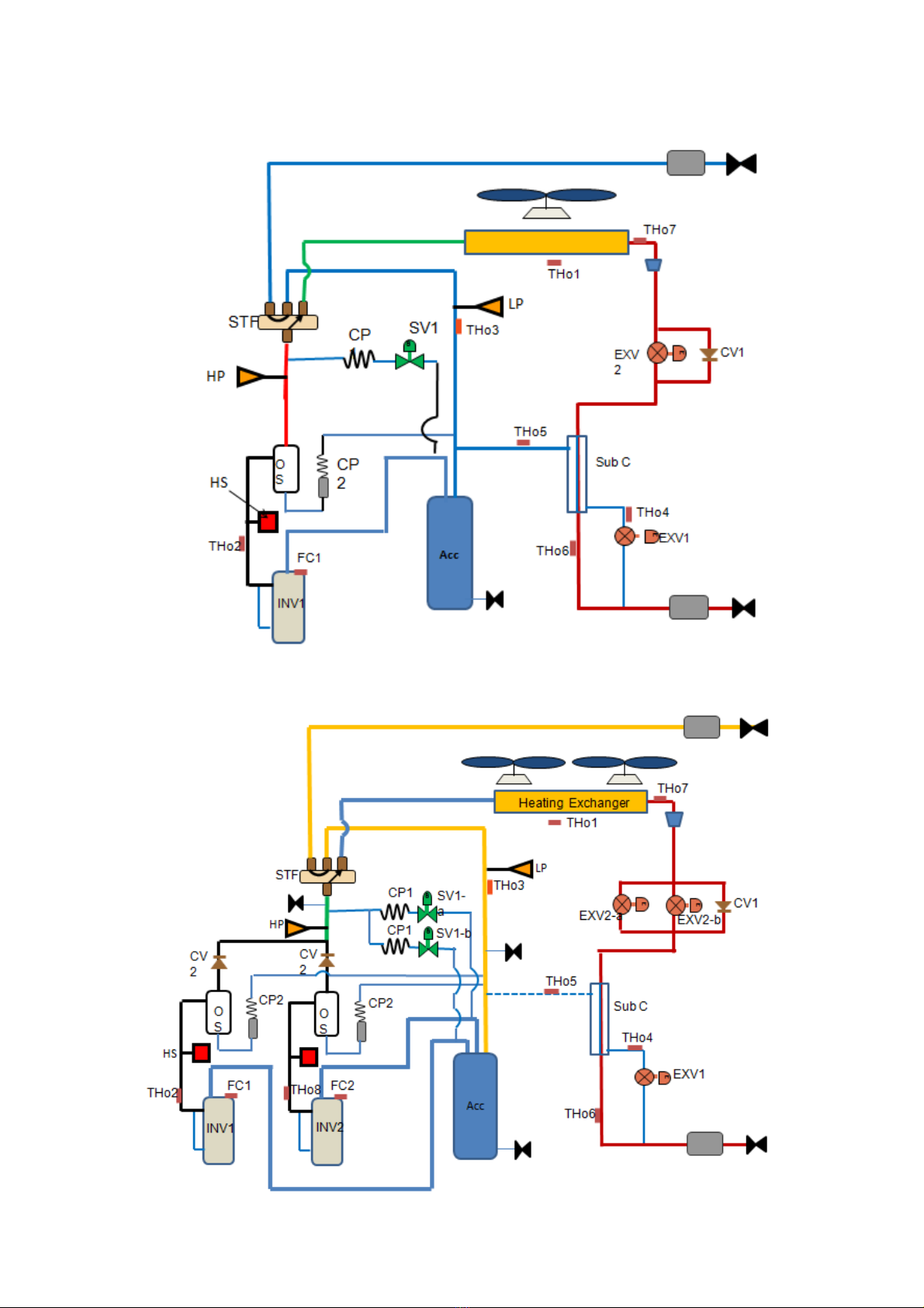
1. Refrigerating System Schematic Diagram
1.1 TIMS080/100/120/140/160AS
4-way valve
Hot air bypass valve
Hot air
bypass
valve
Compressor
Air/liquid separator
Heating expansion
valve
Subcooler
Subcooling expansion
valve
1.2 TIMS180/200/220/240/260/280/300/320AS
4-way valve
Heating expansion
valve
Subcooling expansion valve
15
1.3 TIMS080/100/120/140/160AX
1.4 TIMS180/200/220AX

16
1.5 TIMS080/100/120AST
Copper
silencer
1.6 TIMS140/160/180AST
Copper
silencer
Refrigerant cooling loop
17
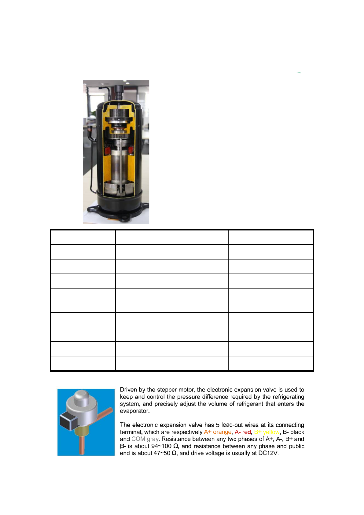
1.7 Key ODU Components
①Compressor
Air inlet
Air jetting port
Air outlet
The inverter compressor adopts the low-
temperature and strong heating scroll compressor
that is equipped with the advanced permanent
magnet synchronous motor. Speed: 20-100RPS;
generally, compressor coil has a resistance value
of 2~4 Ωand insulation resistance ≥1 MΩ.
Features of scroll compressor:
1. Highest efficiency
2. Small rotation torque changes, stable
performance with less vibration and low noises
3. Least components used, simple structure,
compact, low weight and high reliability
4. High requirements for machining precision and
high costs
Model Compressor Item No.
TIMS080-100AS/X E655DHD-65D2YG B7020226
TIMS120AS/X E705DHD-72D2YG B7020796
TIMS140-160AS/X E856DHD-80D2YG B7020743
TITIMS180-240AS
TIMS180-220AX
E655DHD-65D2YG*2 B7020226
TIMS260AS E705DHD-72D2YG*2 B7020796
TIMS280-320AS E856DHD-80D2YG*2 B7020743
TIMS080-120AST DS4GK5052FVS B7020977
TIMS140-180AST AMB78FZDMT B7021045
②Electronic expansion valve
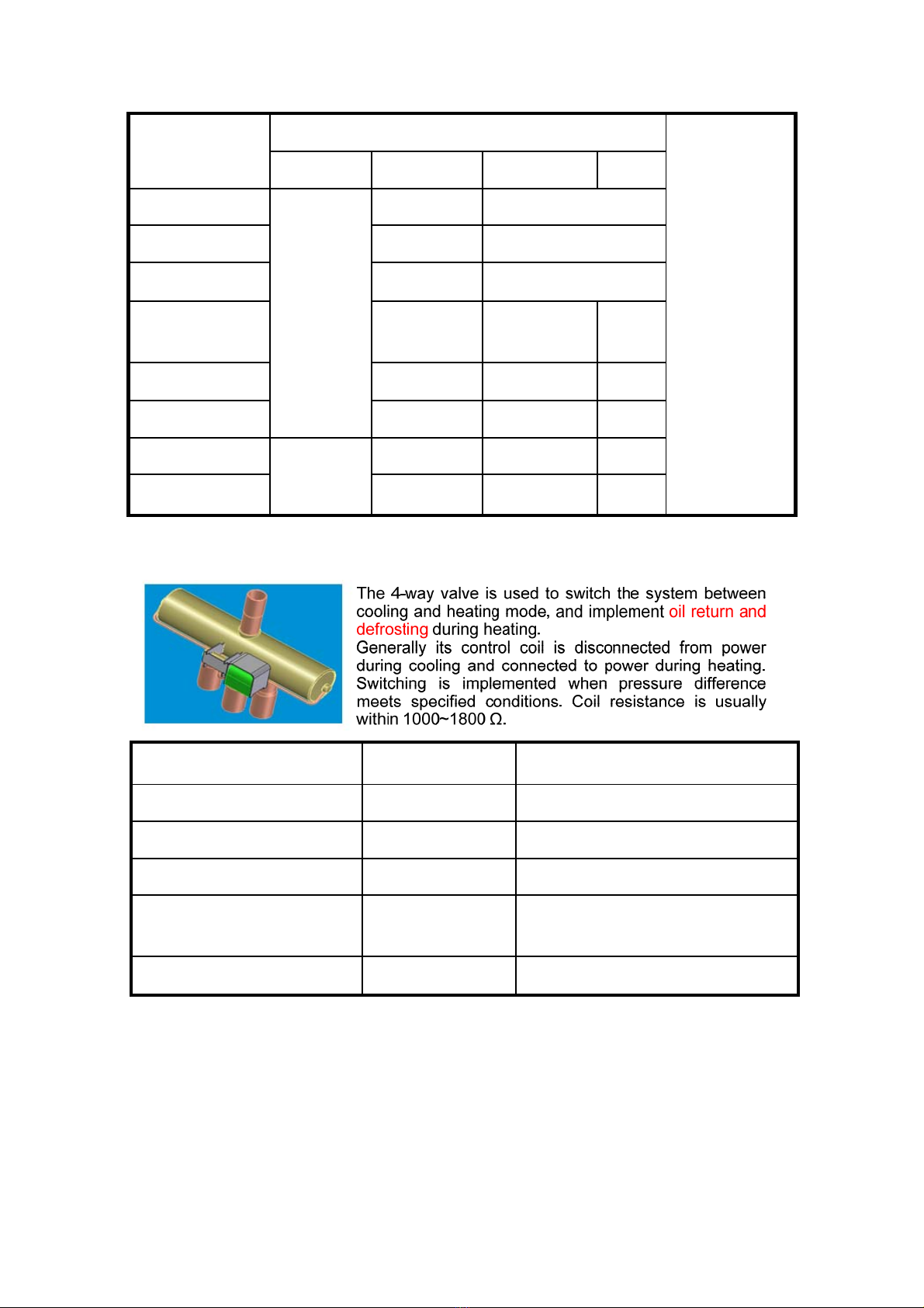
18
Model Electronic expansion valve Item No.
UKV18D202
B4040079
UKV-30D209
B4040083
UKV-32D210
B4040147
UKV-40D305
B4040107
DPF(TS1)
1.65C-03
B4040283
EXV1 EXV2 EXV3 EXV4
TIMS080-100AS/X
UKV18D202
UKV30D209 /
TIMS120AS/X UKV32D210 /
TIMS140-160AS/X UKV-40D305 /
TIMS180-240AS
TIMS180-220AX UKV-40D305 UKV-40D305 /
TIMS260AS UKV-40D305 UKV-40D305 /
TIMS280-320AS UKV-40D305 UKV-40D305 /
TIMS080-120AST DPF(TS1)
1.65C-03
UKV30D209 / /
TIMS140-180AST UKV-40D305 / /
③4-way valve
Model 4-way valve Item No.
TIMS080-100AA STF-H0712 B4050052
TIMS120-180AA STF-2011G B4050061
TIMS080-120AS/X STF-H0712 B4050052
TIMS140-260AS
TIMS140-220AX
STF-2011G B4050061
TIMS280-320AS STF-2501G B4050013

19
④Air/liquid separator
Model Air/liquid separator capacity L Item No.
TIMS080-160AS
TIMS180-260AS
TIMS080-160AX
TIMS180-220AX
TIMS080-180AST
24 B7010147
B7010148
B7010145
B7010166
B7010147
TIMS280-320AS 30 B7010152
⑤Oil separator
Model Oil separator capacity L Item No.
TIMS080-160AS
TIMS180-260AS
TIMS080-160AX
TIMS180-220AX
TIMS280-320AS
TIMS080-180AS T
1.5
B7010167

20
⑥Pressure sensor
The pressure sensor converts the system pressure value into voltage signal, and then
sends the signal to main board, thereby ensuring system operation and pressure
protection. Falling into two categories (low pressure and high pressure), the pressure
sensor has 3 lead-out wires.
High pressure sensor (red) Vout=0.87*Pg+0.5
Low pressure sensor (blue) Vout=2*Pg+0.5
Pg=Mpa (gage pressure)
Model High/low pressure sensor Item No.
TIMS080-160AS
TIMS180-260AS
TIMS080-160AX
TIMS180-220AX
TIMS280-320AS
TIMS080-180AST
2HMP6-1 (red)/2HMP6-2 (black) B5180406/B5180361
2. Exploded view/3D diagram
2.1 TIMS080/100/120AS/AX
This manual suits for next models
369
Table of contents
Other TICA Inverter manuals


Popular Inverter manuals by other brands


SolaX Power
SolaX Power X3-Fit-G4 installation manual

Fuji Electric
Fuji Electric Frenic-Mini instruction manual

Briggs & Stratton
Briggs & Stratton P4500 Operator's manual

Fuji Electric
Fuji Electric frenic 5000g11s instruction manual

Phocos
Phocos SI700-12110 user manual

Eversolar
Eversolar Eversol-TL2100 installation instructions


