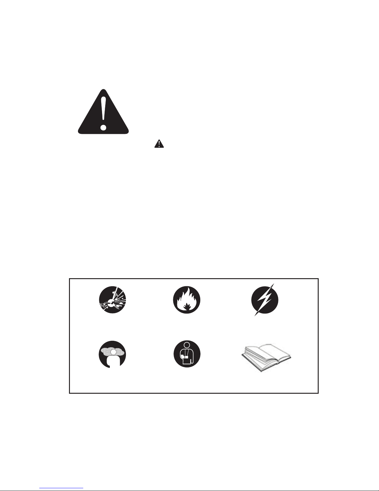
Jet JIN3500E User manual

Operation MANUAL
•
®Registered trademark of JET Equipment & Tools Ltd. M14-IPEWASH
www.jetgroupbrands.com
Important Safety Instructions
Save These Instructions
Inverter
JIN3500E

2
table of contents
Safety
4 Introduction
5Safety Warnings
6 Safety Information
Control Function
9 Description
9 Control Panel
10 3 in 1 Switch Knob
10 Engine Smart Control
11 Digital Display Meter
11 Oil Warning Light
12 Overload Indicator Light (Red)
12 AC Pilot Light (Green)
13 DC Protector
13 Ground (Earth) Terminal
13 Parallel Operation Outlets
13 Brake
Pre-Operation
14 Fuel
15 Engine oil
Operation
16 Operation
16 Staring the engine
17 Stopping the engine
18 Alternating Current (AC) connection
19 Battery Charging
20 AC Parallel Operation
21 AC Parallel Operation Applications
22 Application Range

3
table of contents
Maintenance
24 Maintenance
24 Maintenance Chart
26 Spark Plug Inspection
26 Carburetor Adjustment
27 Clean Fuel Filter
27 Engine Oil Replacement
28 Air Filter
28 Muffler Screen
Storage
30 Drain the Fuel
30 Engine
Troubleshooting
31 Engine Can’t Start
31 Generator Won’t Produce Power
Parameters
32 Parameters
Wiring Diagram
33 120V

4
introduction
Using the Operator’s manual
The operating manual is an important part of your generator and
should be read thoroughly before initial use, and referred to often
to make sure adequate safety and service concerns are being ad-
dressed.
Reading the owner’s manual thoroughly will help avoid any personal
injury or damage to your machine. By knowing how best to operate
this machine you will be better positioned to show others who may
also operate the unit.
This manual contains information for the complete range of Case IH
generators, and was written to take you from the safety requirements
to the operating functions of your machine. You can refer back to the
manual at any time to help troubleshoot any specific operating func-
tions, so store it with the machine at all times.
Attention: Read through the complete manual
prior to the initial use of your generator.

5
safety
The safety alert symbol ( ) is used with a signal word (DANGER,
CAUTION, WARNING), a pictorial and/or a safety message to alert
you to hazards.
DANGER you WILL be KILLED or SERIOUSLY HURT if you don’t
follow instructions.
WARNING you CAN be KILLED or SERIOUSLY HURT if you don’t
follow instructions.
CAUTION you CAN be HURT if you don’t follow instructions
NOTICE your generator or other property could be damaged if you
don’t follow instructions.
Save these Instructions
SAFETY WARNINGS
This is the safety alert symbol. It is used to alert
you to potential personal injury hazards. Obey all
safety messages that follow this symbol to avoid
possible injury or death.
Hazard Symbols and Meanings
explosion
kickback read manual
fire electric shock
toxic fumes

6
safety
SAFETY INFORMATION
Read and understand this owner’s manual before operating your
generator. It will help you avoid accidents if you get familiar with your
generator’s safe operation procedures.
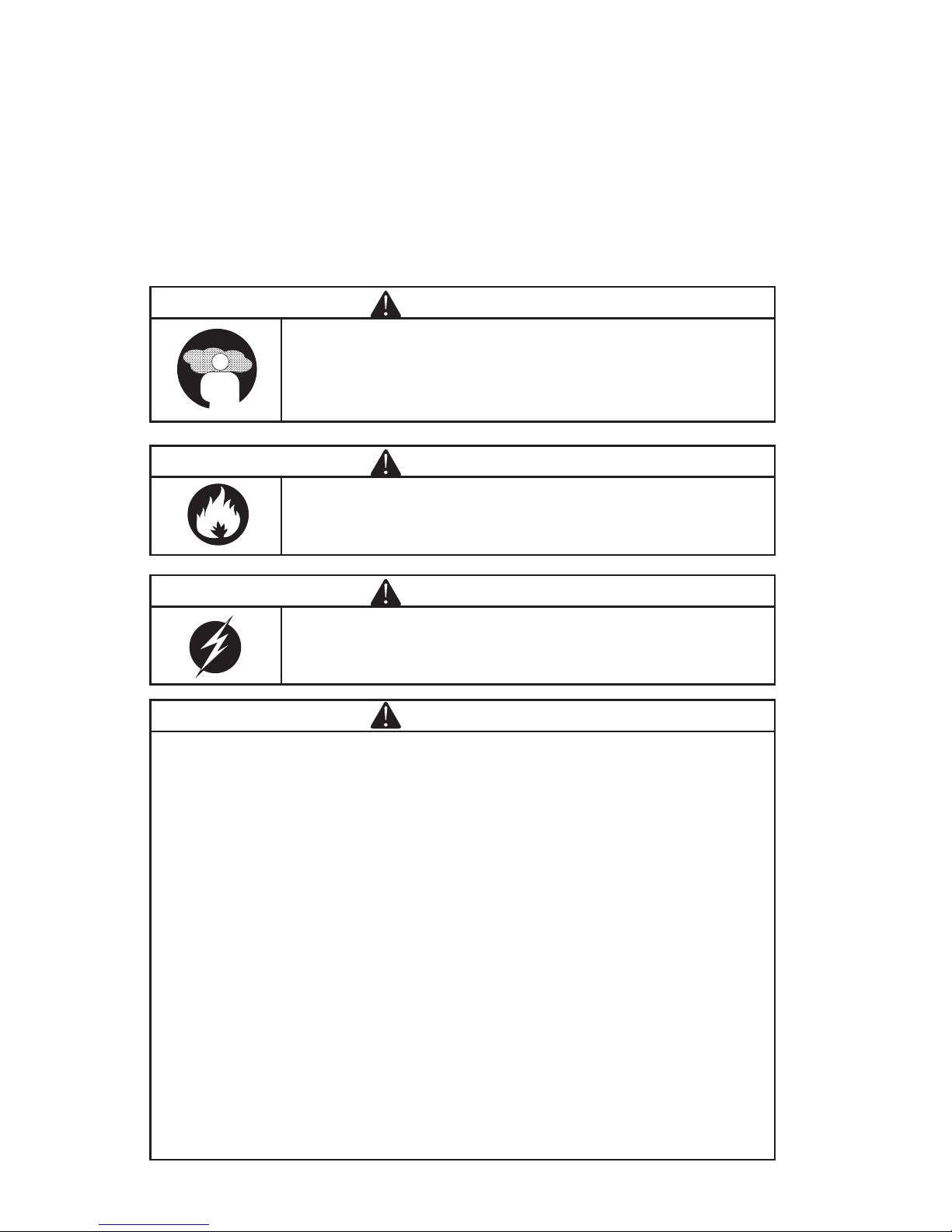
DANGER
Do not use indoors.
DANGER
Keep the machine clean and avoid spilling combus-
tibles including gasoline on it.
WARNING
Do not use in a wet condition.
WARNING
• Turn the generator “OFF” when adding fuel.
• Don’t add fuel near the flammable thing or cigarette.
• Keep children and pets away from the area of operation. Do not
place flammable objects close to the exhaust when generator
operation. Keep it at least 1m away from inflammables.
• The generating set must not be connected to other power
sources, such as the power company supply main. Protection
against electrical shock depends on circuit breaker specially
matched to the generating set. Due to high mechanical stresses
only, tough rubber sheathed flexible cable (in accordance with ICE
245 or the equivalent should be used. When using extension lines
or mobile distribution networks the total length of lines for a cross
section of 1.5 mm should not exceed 60 m; for a cross section
of 2.5 mm this should not exceed 100 m. Electrical equipment
(including lines and plug connections) should not be defective.
• Utilize safe proper grounding. Use the ground wire with enough
electric flux. Ground wire diameter: 0.12mm/A.
• The generator surface has high temperature, avoid scalding. Pay
attention to the warnings on the generating set.

7
safety
CONNECTION TO A HOME POWER SUPPLY
If the generator is to be used as standby home power supply the
connection is to be performed by a qualified electrician. When loads
are connected to the generator, carefully check whether electrical
connections are safe and reliable. Any improper connection may
cause damage to the generator or cause a fire.
• Keep generator at least 3ft (1m) away from buildings or other
structures.
• Only operate generators in a dry, well ventilated area.
• Keep exhaust pipe clear of foreign objects.
• Keep generator away from open flame. No Smoking!
• Keep generator on a stable and level surface.
• Do not block generator air vents with paper or other material.
DO NOT place any heavy objects on the generator. Select and place
the generator in the proper position of the transport vehicle so that
the generator will not move or fall down. Secure the generator if
necessary.

8
safety
UNIT SAFETY SYMBOLS
There is the warning label on the machine to remind you of the safety
regulations.
SYMBOLS
Read the safety instructions before using the generator.
Only fill the generator in well-ventilated areas and keep
it away from open flames sparks and cigarettes Spilled
fuel should be soaked up immediately.
Switch off the engine and let it cool down before filling
the generator Fuel is easily flammable and may even
explode under certain circumstances.
Gases such as carbon monoxide (colourless and
odorless gas) are produced during operation which
may lead to suffocation. Only use the generator in well
ventilated areas.
Warning! Dangerous voltages are present when the
generator is in operation. Generator must always be
switched off before performing maintenance works.
Wear ear protection when operating the generator.
Disconnect all devices from the connections before
performing maintenance work before leaving the device
and after switching it off.
The generator may not be connected to the public pow-
er supply When the device is falsely connected there is
a risk of fire material damage and even a fatal electric
shock being suffered by the operator as is also the case
when performing works on the public power supply.

9
control function
1. Fuel tank cap
2. Handle
3. Control panel
4. Inverter parts
5. Battery
6. Brake
7. Recoil starter grip
8. Shutter
9. Muffler
10. Oil drain bolt
11. Oil filler cap
12. Air cleaner
13. Carburetor
14. Spark plug
15. Left cover
16. Oil observation window
Control Function
DESCRIPTION
CONTROL PANEL
120V
1. AC receptacle
2. AC receptacle
3. AC circuit breaker
4. Multimeter
5. 3 in 1 switch knob
6. DC protector
7. DC receptacle
8. Electric Start
9. ESC (engine start control)
10. Parallel receptacle
11. Ground terminal

10
control function
1. Engine/fuel valve OFF”; Ignition
circuit is switched off. Fuel is switched
off. The engine will not run.
2. Engine switch\fuel valve choke.
“ON” Ignition circuit is switched on.
Fuel is switched on. Choke is switched
on. The engine will run.
3. Engine switch\fuel valve\choke.
“ON” Ignition circuit is switched on.
Fuel is switched on. Choke is switched
on. The engine can be start.
TIP: The choke is not required to start
a warm engine
1. “ON”
When the ESC switch is turned to
“ON”, the economy control unit
controls the engine speed according
to the connected load. The results
are better fuel consumption and less
noise.
2. “OFF”
When the ESC switch is turned to
“OFF”, the engine runs at the rated
(3100r/min) Regard-less of whether is
a load connected or not.
TIP: The choke is not required to start a
warm engine
3 IN 1 SWITCH KNOB
ENGINE SMART CONTROL

11
control function
Liquid crystal display
Normal Operation:
During the normal operation, the
operation key (3) for switching the display
cycle showing: voltage current power-
accumulative time current time.
In case of failed operation:
U> a: AC over voltage, indicating the
character of AC (alternative indication
of AC and digit)
b: DC over voltage, indicating the
character of DC (alternative indication
of DC and digit)
U< a: AC under-voltage, indicating the
character of AC (alternative indication
of AC and digit)
b: DC under-voltage, indicating the
character of DC (alternative indication
of DC and digit)
I> Output over current of generator
Output short circuit of generator
Over heat of generator
Maintenance time
DIGITAL DISPLAY METER
1. Multimeter
2. Liquid crystal display
3. Operating key
4. Oil warming light
5. Overload indicator light
6. AC pilot light
When the oil level falls below the lower level,
the oil warning light comes on and then the
engine stops automatically. Unless you refill
with oil, the engine will not start again.
TIP: If the engine stalls or does not start,
turn the engine switch to “ON” and then
pull the recoil starter. If the oil warning light
flickers for a few seconds, the engine oil is
insufficient. Add oil and restart.
OIL WARNING LIGHT

12
control function
The overload indicator light comes on
when an overload of a connected electrical
device is detected, the inverter control unit
overheats, or the AC output voltage rises.
Then, the AC protector will trip, stopping
power generation in order to protect the
generator and any connected electric
devices. The AC pilot light (Green) will go
off and the overload indicator light (Red) will
stay on, but the engine will not stop running.
When the overload indicator light comes on
and power generation stops, proceed as
follows:
1. Turn off any connected electric devices
and stop the engine.
2. Reduce the total wattage of connected
electric devices within the rated output.
3. Check for blockages in the cooling air
Inlet and around the control unit. If any
blockages are found remove.
4. After checking, restart the engine.
TIP: The overload indicator light may
come on for a few seconds at first when
using electric devices that require a large
starting current, such as a compressor or a
submergible pump. However, this is not a
malfunction.
The AC pilot light comes on when the engine
starts and produces power.
OVERLOAD INDICATOR LIGHT (RED)
AC PILOT LIGHT (GREEN)

13
control function
The DC protector turns to “OFF”
automatically when electric device being
connected to the generator is operating and
current above the rated flows. To use this
equipment again, turn on DC protector by
pressing its button to “ON”.
1. “ON” Direct current is output.
2. “OFF” Direct current is not output.
Ground (Earth) terminal (1) connects the
earth line for prevention of electric shock.
When the electric device is earthed, always
the generator must be earthed.
DC PROTECTOR
GROUND (EARTH) TERMINAL
NOTICE
• Reduce the load of the connected electric device below the speci-
fied rated output of the generator if the DC protector turns off. If
the DC protector turns off again, stop using the device immedi-
ately and consult a franchised dealer.
This is the terminal for connecting special
cables for parallel running of two generator.
The parallel running requires two generator
and the special cables. (The rated output
in parallel running is 6.0Kva and the rated
current is 60A/100V;50A/120V;26A/230V.)
The handing, operation procedure and
the notes on usage are described in the
PARALLEL RUNNING KIT OWNER’S
MANUAL included in the Parallel.
During the operation and idle period of
machine, brake timely and switch to “STOP”.
In case of the machine is required to be
moved, switch the brake to “RUN”.
PARALLEL OPERATION OUTLETS
BRAKE

14
pre-operation
Make sure enough gasoline is in the fuel tank.
1. Fuel level gauge
Recommended fuel: Unleaded gasoline | Fuel tank capacity: Total:
10.0L
FUEL
Pre-Operation
NOTICE
• Pre-operation checks should be made each time operation.
WARNING
• The engine and muffler will be very hot after the engine has been
run. Avoid touching the engine and muffler while they are still hot
with any part of your body or clothing during inspection or repair.
WARNING
• Fuel is highly flammable and poisonous. Check “SAFETY
INFORMATION”(See page 2-5) carefully before filling.
• Do not overfill the fuel tank, otherwise it may overflow when the
fuel warms up and expands. After filling the fuel, make sure the
fuel tank cap is tightened securely.
• Immediately wipe off spilled fuel with a clean.
• Use only unleaded gasoline. The use of leaded gasoline
• Will cause severe damage to internal engine parts.

15
pre-operation
The generator has been shipped without
engine oil. Do not start the engine until
filled with the sufficient engine oil.
Do not tilt the generator when adding
engine oil. This could result in overfilling
and damage to the engine.
Recommended engine oil: SAE 10W -30
Recommended engine oil grade:
API Service SE type or higher
Engine oil quantity: 0.6 L
ENGINE OIL

16
operation
Before starting the engine, do not
connect any electric devices.
Turn the ESC switch to “OFF” (1)
Turn the 3 in 1 switch to “CHOKE”
a. Ignition circuit is switched on.
b. Fuel is switched on.
c. Choke is switched off.
TIP: The choke is not required to start a
warm engine. Push the choke knob in to
the position “ON”.
TIP:
• The generator can be used with the rated output load at standard
atmospheric conditions.
• “Standard atmospheric conditions ”; Ambient temperature 25.
• Barometric pressure 100kPa; Relative humidity 30%
• The output of the generator varies due to change temperature,
altitude (lower air pressure at higher altitude) and humidity.
• The output of the generator is reduced when the temperature, the
humidity and the altitude are higher than standard atmospheric
conditions.
• Additionally, the load must be reduced when using in confined
areas, as generator cooling is affected.
STARTING THE ENGINE
Operation
NOTICE
• Never operate the engine in a closed area or it may cause un-
consciousness and death within a short time. Operate the engine
in a well ventilated area. The generator has been shipped without
engine oil. Do not start the engine until filled with the sufficient
engine oil.

17
operation
Electric Start
Turn the engine switch on the control
panel to ON Or press it to START if it
is electrical start state then generator
unit can be started In order to extend
the service life of the storage battery do
not press on the switch for more than 3
seconds and the interval between two
pressings should be longer than 10
seconds.
Recoil Start
Grasp the carrying handle firmly to
prevent the generator from falling over
when pulling the recoil starter.
After the engine starts, warm up the
engine until the engine does not stop
when the choke knob is returned to the
“ON” position. (3)
TIP:
When starting the engine, with the
ESC “ON” and there is no load on the
generator:
In ambient temperature below 0ºC (32ºF),
the engine will run at the rated (3600r/
min) for 5 minutes to warm up the engine.
In ambient temperature below 5ºC (41ºF),
the engine will run at the rated r/min
(3600r/min) for 3 minutes to warm up the
engine.
The ESC unit operates normally after the
above time period, while the ESC is “ON”.
Release the load.
STOP THE ENGINE

18
operation
TIP: Turn off any electric devices.
1. Disconnect any electric devices.
2. Turn the ESC to “OFF” (1).
3. Turn the 3 in 1 switch to “OFF” (2).
a. Ignition circuit is switched off.
b. Fuel valve is switched off.
ALTERNATING CURRENT (AC) CONNECTION
NOTICE
• Be sure all electric devices including the lines and plug connec-
tions are in good condition before connection to the generator.
• Be sure the total load is within generator rated output.
• Be sure the receptacle load current is within receptacle rated cur-
rent.
WARNING
• Be sure any electric devices are turned off before plugging them
in.
TIP: Make sure to ground (Earth) the generator. When the electric
device is earthed, always the generator must be earthed.
1. Start the engine.
2. Turn the ESC to “ON”.
3. Plug in to AC receptacle.
4. Make sure the AC pilot light is on.
5. Turn on any electric devices.
TIP: The ESC must be turned to “OFF” before increasing engine speed
to rated rpm.
• Most motorized appliances require more than their electrical rating for
startup. When an electrical motor is started, the overload indicator (red)
may come on. This is normal if the overload indicator (red) goes off
within 4 seconds. If the overload indicator (red) stays on, consult your
generator dealer.

19
operation
• If the generator is connected to multiple loads or electricity consumers,
please remember to first connect the one with the highest starting
current. And last connect the one with the lowest starting current.
• If the generator is overloaded, or if there is a short circuit in a connected
appliance, the overload indicator (red) will go ON. The overload
indicator (red) will stay ON, and after about 4 seconds, the connected
appliance(s) will shut off, and the output indicator (green) will go OFF.
Stop both engines and investigate the problem. Determine if the cause
is a short circuit in a connected appliance or an overload, correct the
problem and restart the generator.
BATTERY CHARGING
TIP:
• The generator DC rated voltage is 12V.
• Start the engine first, and then connect the generator to the battery
for charging.
• Before starting to charge the battery, make sure that the DC
protector is turned on.
1. Start the engine.
2. Connect the red battery charger lead to the positive (+) battery
terminal.
3. Connect the black battery charger lead to the negative (-) battery
terminal.
4. Turn the ESC “OFF” to start battery charging.
NOTICE
• Be sure the ESC is turned off while charging the battery.
• Be sure to connect the red battery charger lead to the positive (+)
battery terminal, and connect the black lead to the negative (-) bat-
tery terminal. Do not reverse these positions.
• Connect the battery charger leads to the battery terminals se-
curely so that they are not disconnected due to engine vibration or
other disturbances.
• Charge the battery in the correct procedure by following instruc-
tions in the owner’s manual for the battery.
• The DC protector turns off automatically if current goes above the
rated flow during battery charging. To restart charging the battery,
turn he DC protector on by pressing its button to “ON”. If the DC
protector turns off again, stop charging the battery immediately
and consult a servicing dealer.

20
operation
AC PARALLEL OPERATION
TIP:
• Follow instructions in the owners manual for the battery to
determine the end of battery charging.
• Measure the specific gravity of electrolyte to determine if the battery
is fully charged. At full charge, the electrolyte specific gravity is
between 1.26 and 1.28.
• It is advisable to check the specific gravity of the electrolyte at least
once every hour to prevent overcharging the battery.
Before connection an appliance to either generator, make sure that it
is in good working order and that its electrical rating does not exceed
that of the receptacle.
During parallel operation, the ESC switch should be in the same posi-
tion on both generators.
1. Connect the parallel operation cable between the generator to
either the main generator or companion generator following the
instructions supplied with the cable kit.
2. Start the engines and make sure the output indicator (green) on
each generator comes on.
3. Plug an appliance into the AC receptacle.
4. Turn on the appliance.
WARNING
• Never smoke or use broken connectors on the battery while
charging. Sparks may ignite the battery gas.
• Battery electrolyte is poisonous and dangerous, causing severe
burns, etc. contains sulfuric (sulphuric) acid. Avoid contact with
skin, eyes or clothing.
• Antidote:
EXTERNAL: Flush with water.
INTERNAL: Drink large quantities of water or milk. Follow with
milk of magnesia, beaten egg or vegetable oil . Call physician
immediately.
EYES: Flush with water for 15 minutes and get prompt medical
attention.
• Batteries produce explosive gases. Keep sparks, flame,
cigarettes, etc., away. Ventilate when charging or using in closed
space. Always wear eye protection when working near batteries.
• Keep out of reach of children.
Table of contents
Popular Inverter manuals by other brands

Daihen
Daihen OTC CPTX-I 400 2W owner's manual

Mitsubishi Electric
Mitsubishi Electric FR-F800 instruction manual

Elenco Electronics
Elenco Electronics GFG-8016D instruction manual

FRONIUS
FRONIUS xPrimo GEN24 4.0 Plus operating instructions

Lenze
Lenze E931E Series Hardware manual

Lindy
Lindy 32628 user guide