Tiger Aircraft AG-5B Series User manual

T/QEK
AIKCKAff
AG-5B
SERIES
N.UUNTENANCE~AL
Table S-03
INSPECTION PROCEDURE GUIDELINE
TIQEK
~IKtKAfT
MODEL
AG-SB
ANNUAL
OR
100-
HOUR
INSPECTION
PROCEDURE
ANNUAL
OR
100-
HOUR
INSPECTION
PROCEDURE
GUIDELINE
FAR
43.15
(c)
(1)
states: "Each person performing
an
annual or 100-hour inspection shall
use
a check list
while
performing
the
inspection. The check list
may
be
of
the
person's
own
design,
one
provided
by
the
manufacturer
of
the
equipment being inspected, or
one
obtained
from
an-
other source.
This
check list must include
the
scope
and
detail
of
the
items contained in
appen-
dix
D
to
this
part
and
paragraph (b)
of
this
section."
The
following
pages contain a comprehen-
sive
annual or
100
-hour inspection procedure check
list.
OWNER'S
NAME
STREET
ADDRESS
CITY
STATE
ZIP
CODE
REGISTRATION
NO.
SERIAL
NO.
AIRFRAME
HOURS
DATE
INSPECTION
COMPLETED
SERVICING
AGENCY
CITY
REPAIR
STATION
No.
(if
applicable)
Check
for
conformity with FAASpecifications, Airworthiness
Directives
and
Tiger Aircraft Service Bulletins
and
Letters.
NOTE
It
is
recommended that reference
be
made
to
the
applicable
maintenance handbook, service bulletins, letters, installation
instructions,
and
vendor specifications
for
torque values,
clearances, settings, tolerances
and
other specification
data.
STATE
Chapter 5
Page
5-11
Rev.
08/08/05
T/QER
AIKCKAff
AG-5B SERIES
MAINTENANCE MANUAL
Table 5-03 (continued)
MODELAG-5B
ANNUAL
OR
100-
HOUR
INSPECTION PROCEDURE
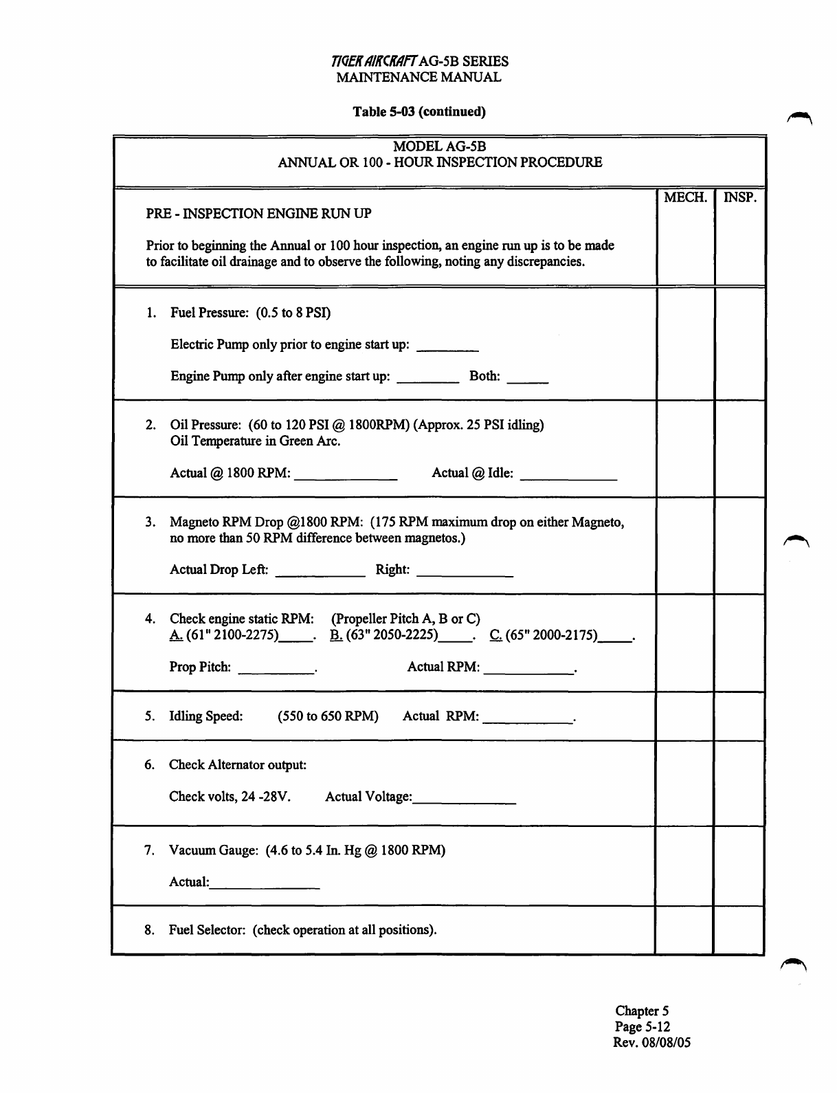
PRE -INSPECTION ENGINE
RUN
UP
Prior to beginning the Annual
or
100 hour inspection,
an
engine run
up
is to
be
made
to facilitate oil drainage and to observe the following, noting any discrepancies.
1.
Fuel Pressure: (0.5 to 8 PSQ
Electric Pump onlyprior to engine start up:
__
_
Engine Pump only after engine start up:
__
_ Both:
2. Oil Pressure: (60 to 120 PSI @ 1800RPM) (Approx. 25 PSI idling)
Oil Temperature
in
Green Arc.
Actual@
1800 RPM:
____
_
Actual@
Idle:
____
_
3. Magneto RPM Drop @1800 RPM: (175 RPM maximum drop
on
either Magneto,
no more than
50
RPM difference between magnetos.)
Actual Drop Left:
____
_ Right:
-----
4. Check engine static RPM: (Propeller PitchA, B
or
C)
A. (61" 2100-2275)
__
. B. (63" 2050-2225)
__
. C. (65" 2000-2175)
__
.
Prop Pitch:
___
_ Actual RPM:
-----
5.
Idling Speed: (550 to 650 RPM) Actual
RPM:-----
6. Check Alternator output:
Check volts, 24 -28V. Actual Voltage:
_____
_
7. Vacuum Gauge: (4.6 to 5.4 In.
Hg@
1800 RPM)
Actual:
_____
_
8. Fuel Selector: (check operation
at
all positions).
MECH. INSP.
Chapter 5
Page 5-12
Rev. 08/08/05
T/QEK
AIKCKAFT
AG-5B
SERIES
MAINTENANCE MANUAL
Table 5-03 (continued)
MODELAG-5B
ANNUAL
OR
100-HOUR INSPECTION PROCEDURE
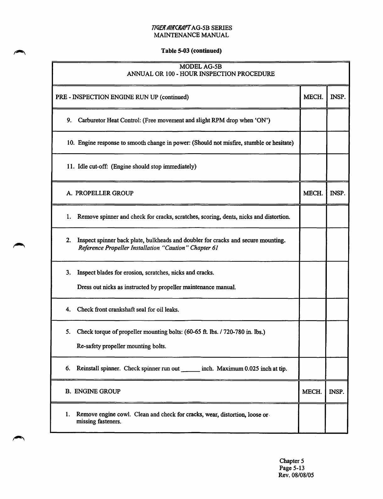
PRE -INSPECTION ENGINE
RUN
UP
(continued)
9.
Carburetor Heat Control: (Free movement and slight
RPM
drop when 'ON')
10.
Engine response
to
smooth change in power: (Should not misfrre, stumble or hesitate)
11.
Idle cut-off: (Engine should stop immediately)
A.
PROPELLER
GROUP
1.
Remove spinner and check
for
cracks, scratches, scoring, dents, nicks and distortion.
2.
Inspect spinner back plate, bulkheads and doubler
for
cracks and secure mounting.
Reference Propeller Installation "Caution" Chapter
61
3.
Inspect blades for erosion, scratches, nicks and cracks.
Dress out nicks
as
instructed
by
propeller maintenance manual.
4.
Check front crankshaft seal
for
oil leaks.
5.
Check torque
of
propeller mounting bolts: (60-65
ft.
lbs.
I 720-780
in.
lbs.)
Re-safety propeller mounting bolts.
6.
Reinstall spinner. Check spinner
run
out
___
inch.
Maximum 0.025 inch at tip.
B.
ENGINE
GROUP
1.
Remove engine cowl. Clean and check for cracks, wear, distortion, loose or.
missing fasteners.
MECH.
MECH.
MECH.
Chapter 5
Page
5-13
Rev.
08/08/05
INSP.
INSP.
INSP.
T/QER
AIRCRAfT
AG-5B SERIES
MAINTENANCE MANUAL
Table
5-03 (continued)
MODELAG-5B
ANNUAL OR
100-
HOURINSPECTION PROCEDURE
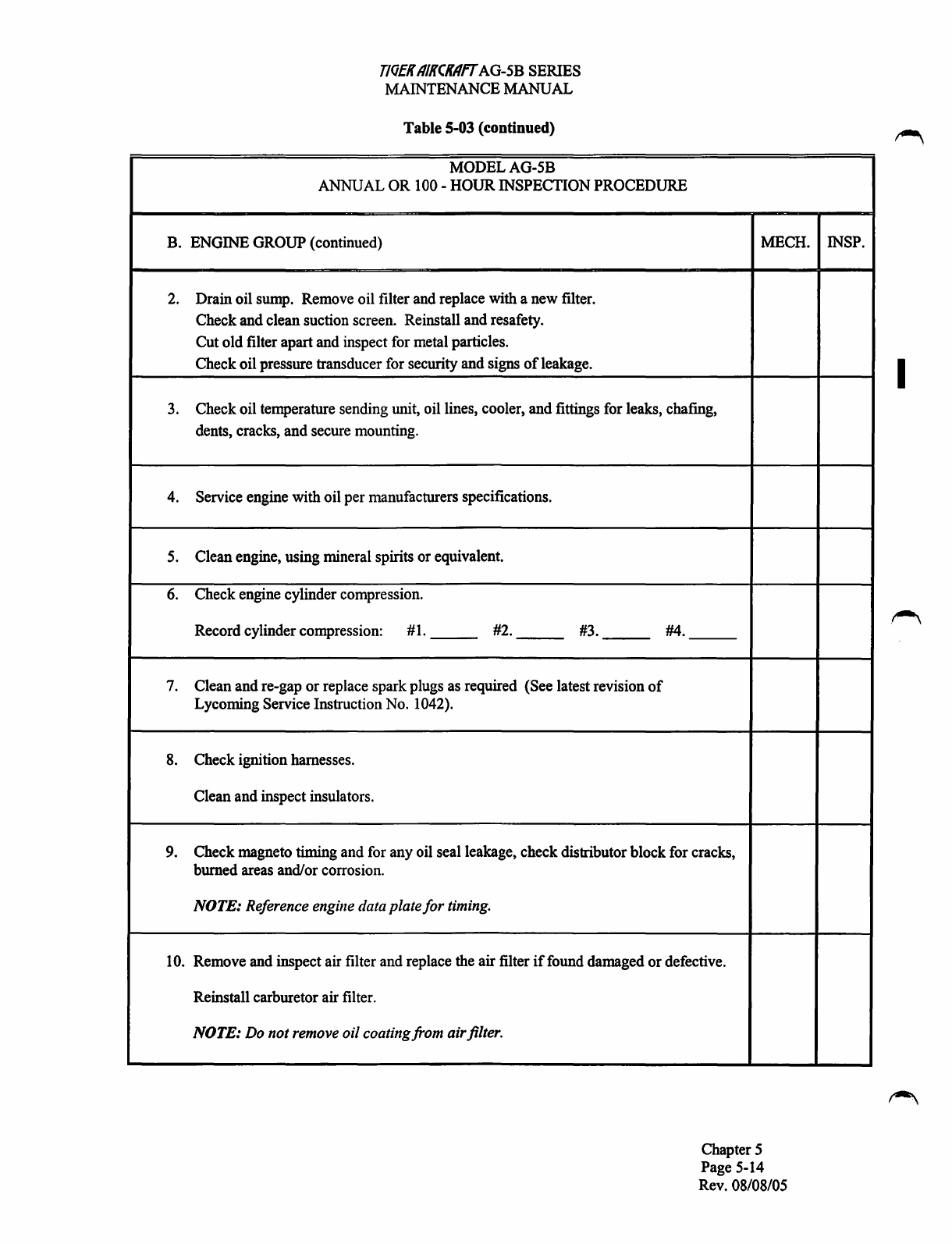
B. ENGINE GROUP (continued)
2. Drain oil sump. Remove oil filter and replace with a new filter.
Check and clean suction screen. Reinstall and resafety.
Cut old filter apart and inspect for metal particles.
Check oil pressure transducer for security and signs
of
leakage.
3. Check oil temperature sending unit, oil lines, cooler, and fittings for leaks, chafmg,
dents, cracks, and secure mounting.
4. Service engine with oil per manufacturers specifications.
5. Clean engine, using mineral spirits or equivalent.
6. Check engine cylinder compression.
Record cylinder compression: #1.
__
#2.
__
#3.
__
7. Clean and re-gap
or
replace sparkplugs as required (See latest revision
of
Lycoming Service Instruction No. 1042).
8. Check ignition harnesses.
Clean and inspect insulators.
#4.
9. Check magneto timing and for any oil seal leakage, check distributor block for cracks,
burned areas and/or corrosion.
NOTE:
Reference engine data plate
for
timing.
10. Remove and inspect air filter and replace the air filter
if
found damaged
or
defective.
Reinstall carburetor air filter.
NOTE:
Do notremove oil coatingfrom airfilter.
MECH. INSP.
Chapter 5
Page 5-14
Rev. 08/08/05
I
T/QER
AIRCRAFT
AG-SB SERIES
MAINTENANCE MANUAL
Table 5-03 (continued)
MODELAG-5B
ANNUAL OR
100-
HOUR INSPECTION PROCEDURE
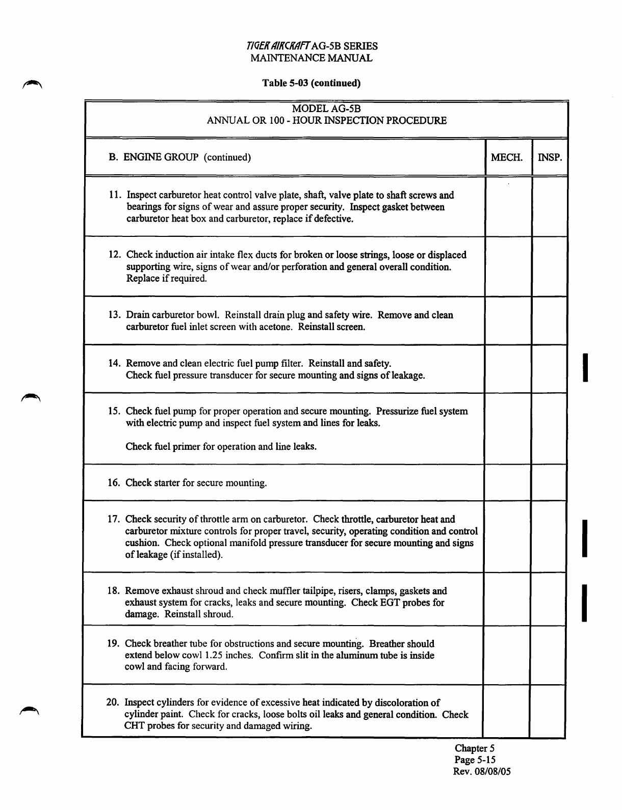
B. ENGINE GROUP (continued)
11. Inspect carburetor heat control valve plate, shaft, valve plate to shaft screws and
bearings for signs
of
wear and assure proper security. Inspect gasket between
carburetor heat box and carburetor, replace
if
defective.
12. Check induction air intake flex ducts for broken
or
loose strings, loose or displaced
supporting wire, signs
of
wear and/or perforation and general overall condition.
Replace
if
required.
13. Drain carburetor bowl. Reinstall drain plug and safety wire. Remove and clean
carburetor fuel inlet screen with acetone. Reinstall screen.
14. Remove and clean electric fuel pump filter. Reinstall and safety.
Check fuel pressure transducer for secure mounting and signs
of
leakage.
15. Check fuel pump for proper operation and secure mounting. Pressurize fuel system
with electric pump and inspect fuel system and lines for leaks.
Check fuel primer for operation and line leaks.
16. Check starter for secure mounting.
17. Check security
of
throttle arm on carburetor. Check throttle, carburetor heat and
carburetor mixture controls for proper travel, security, operating condition and control
cushion. Check optional manifold pressure transducer for secure mounting and signs
ofleakage
(if
installed).
18. Remove exhaust shroud and check muffler tailpipe, risers, clamps, gaskets and
exhaust system for cracks, leaks and secure mounting. Check EGT probes for
damage. Reinstall shroud.
19. Check breather tube for obstructions and secure mountiiig. Breather should
extend below cowl 1.25 inches. Confrrm slit in the aluminum tube is inside
cowl and facing forward.
20. Inspect cylinders for evidence
of
excessive heat indicated
by
discoloration
of
cylinder paint. Check for cracks, loose bolts oil leaks and general condition. Check
CHT probes for security and damaged wiring.
MECH.
Chapter 5
Page 5-15
Rev. 08/08/05
INSP.
I
I
I

T/QEK
AIKCKAfT
AG-5B SERIES
N.UUNTENANCE~AL
Table
5-03 (continued)
MODELAG-5B
ANNUAL OR
100-
HOUR INSPECTION PROCEDURE
B. ENGINE GROUP (continued)
21. Inspect engine mount for cracks and secure mounting. Checkrubber vibration
dampeners for signs
of
deterioration. Replace
if
required.
22. Check all baffles for cracks, loose
or
missing screws and deteriorated seal material.
23. Check alternator for secure mounting and lugs and brackets for cracks. Check
condition and tension
of
alternator drive belt. Replace
if
required. Adjust the
Alternator Belt as follows:
Apply a torque wrench
to
the nut that attaches the pulley to the alternator and apply
force in a clockwise direction, note the torque when the pulley slips. Adjust belt to
the following tension:
Belt Size Condition
Torgue
Slippage
3/8" New 11-13
ft.
lbs.
3/8" Old 7-9 ft.lbs.
Yl"
New 13-15
ft.
lbs.
Yz"
Old 9-10 ft. lbs.
24. Check battery electrolyte level and specific gravity. Clean and tighten battery
terminals. Check battery drain for condition and assure drainage is clear
of
the
aircraft structure.
Note:
GlOOO
equipped
aircraft
have two batteries (check both).
The
Back-Up
Battery
must be replaced every 24 months. See
Chapter
24A
25. Inspect vacuum system components for secure mounting. Check vacuumpump
drive for evidence
of
seal leakage. Replace seal and pump
if
required. Check all
interconnecting lines and fittings for leaks, deterioration and damage.
Replace
if
required.
26. Check ground straps for condition and secure attachment.
27. Check electrical wiring for condition and secure connections including shielded
cable ground connection.
28. Check Alternator Control Unit, Starter Relay and Master SwitchRelay for condition,
operation and installation.
MECH.
Chapter 5
Page 5-16
Rev. 08/08/05
INSP.
I
T/QER
11/RCRflfT
AG-5B SERIES
MAINTENANCE MANUAL
Table
5-03 (continued)
MODELAG-5B
ANNUAL
OR
I
00-
HOUR
INSPECTION PROCEDURE
B. ENGINE GROUP (continued)
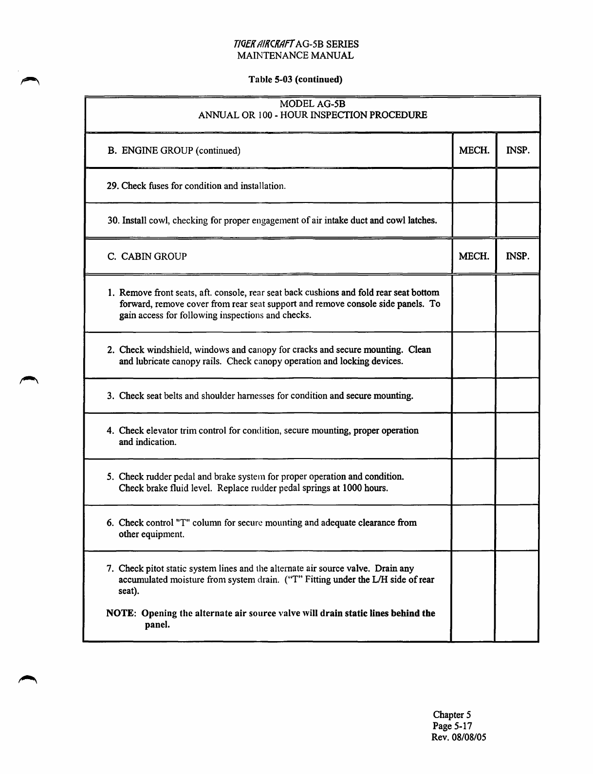
29. Check fuses for condition and installation.
30. Install cowl, checking for proper engagement
of
air intake duct and cowl latches.
C. CABIN GROUP
1.
Remove front seats, aft. console, rear seat back cushions and fold rear seatbottom
forward, remove cover from rear seat support and remove console side panels.
To
gain access for following inspections and checks.
2. Check windshield, windows and canopy for cracks and secure mounting. Clean
and lubricate canopy rails. Check canopy operation and locking devices.
3. Check seat belts and shoulder harnesses for condition
and
secure mounting.
4. Check elevator trim control for condition, secure mounting, proper operation
and indication.
5. Check rudder pedal and brake system for proper operation
and
condition.
Check brake fluid level. Replace rudder pedal springs at 1000 hours.
6. Check control "T" column for secure mounting and adequate clearance from
other equipment.
7. Check pitot static system lines and the alternate air source valve. Drain
any
accumulated moisture from system drain. ("T" Fitting under the L/H side
of
rear
seat).
NOTE:
Opening
the
alternate
air
source
valve will
drain
static
lines
behind
the
panel.
MECH.
MECH.
Chapter 5
Page 5-17
Rev. 08/08/05
INSP.
INSP.
TIOEK
11/:TCK/IFT
AG-5B SERIES
MAINT!::\A1\CE MANUAL
TabL.· 5-03 (continued)
- - -
7\'IODEL
AG-5B
ANNUAL OR lOll- IlOUR INSPECTION PROCEDURE
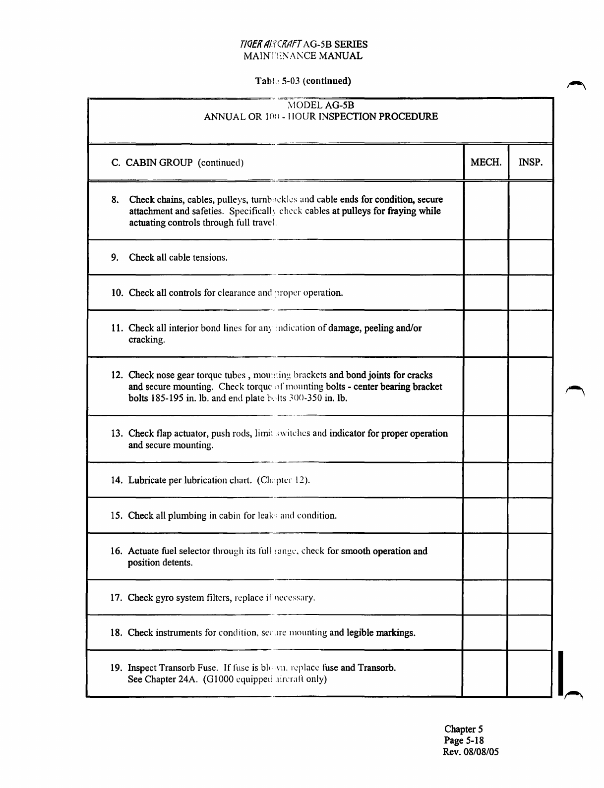
C. CABIN GROUP (continued) MECH.
8. Check chains, cables, pulleys,
turnbtt~.:klcs
and cable ends for condition, secure
attachment and safeties. Specificall:. check cables at pulleys for fraying while
actuating controls through full travc
l.
9. Check all cable tensions.
10. Check all controls for clearance and i)ropcr operation.
11. Check all interior bond lines for any indication
of
damage, peeling and/or
cracking.
12. Check nose gear torque
tubes,
mom:~ing
brackets and bondjoints for cracks
and secure mounting. Check torque
')
rmounting bolts -center bearing bracket
bolts 185-195 in. lb. and end plate b•lts
~00-350
in.
lb.
13. Check flap actuator, push rods, limit ;witches and indicator for proper operation
and secure mounting.
14. Lubricate
per
lubrication chart. (Ch<:ptcr
12).
-
15. Check all plumbing in cabin for leak,; and condition.
16. Actuate fuel selector through its
full
:angl',
check for smooth operation and
position detents.
-
17. Check gyro system filters, replace irnecessary.
18. Check instruments for condition.
se(
trc
mounting and legible markings.
19. Inspect Transorb Fuse.
If
fuse
is
bl(
vn. replace ihse and Transorb.
See Chapter 24A.
{GlOOO
equipped
,tirnan
only)
Chapter 5
Page 5-18
Rev. 08/08/05
INSP.
'~

T/QEK
AIKCKAfT
AG-5B SERIES
N.UUNTENANCE~AL
Table 5-03 (continued)
MODELAG-5B
ANNUAL OR
100-
HOUR INSPECTION PROCEDURE
C. CABIN GROUP (continued) MECH.
20. Check electrical wiring, switches, lights and electronic equipment for condition
and security. Test the Emergency Buss Dual Diode. (Reference Chapter 24A,
01000
equipped aircraft only.)
21. Inspectbaggage compartment, baggage door and cargo tie downs.
22. Inspect all placards in cabin for condition and legibility.
23. Inspect the emergency locator transmitter (ELT) for security, operation and
battery expiration date.
24. Reinstall items removed in item 1
of
this section.
25. Check fresh air vents for proper operation.
D. FUSELAGE AND EMPENNAGE GROUP MECH.
1.
Remove tailcone (stinger) and empennage inspection covers.
2. Inspect exterior surfaces for condition and damage. Assure all drain holes in
bottom
of
fuselage are unobstructed.
3. Inspect bond lines for any indication
of
damage, peeling separation and/or cracks.
Chapter 5
Page 5-19
Rev. 08/08/05
INSP.
I
INSP.
T/QEK
AIKCKAff
AG-5B
SERIES
~NANCE
MANUAL
Table
5-03
{continued)
MODELAG-5B
ANNUAL
OR
100-HOUR INSPECTION
PROCEDURE
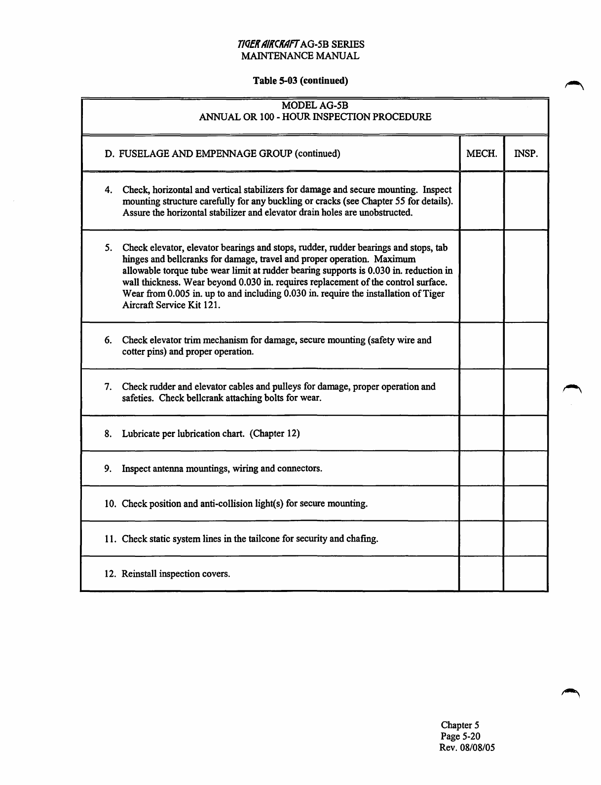
D.
FUSELAGE
AND
EMPENNAGE
GROUP
(continued)
4.
Check,
horizontal and vertical stabilizers
for
damage
and
secure mounting. Inspect
mounting structure carefully for
any
buckling or cracks (see Chapter
55
for
details).
Assure
the
horizontal stabilizer
and
elevator drain
holes
are
unobstructed.
5.
Check elevator, elevator bearings
and
stops, rudder, rudder bearings
and
stops,
tab
hinges
and
bellcranks
for
damage,
travel and proper operation. Maximum
allowable torque tube wear limit at rudder bearing supports
is
0.030
in.
reduction in
wall
thickness. Wear beyond 0.030 in. requires replacement
of
the
control surface.
Wear
from
0.005
in.
up
to
and
including 0.030
in.
require
the
installation
of
Tiger
Aircraft Service Kit
121.
6.
Check elevator trimmechanism
for
damage,
secure mounting (safety
wire
and
cotter pins)
and
proper operation.
7.
Check rudder
and
elevator cables
and
pulleys
for
damage,
proper operation
and
safeties. Check bellcrank attaching bolts
for
wear.
8.
Lubricate per lubrication chart. (Chapter
12)
9.
Inspect antenna mountings, wiring
and
connectors.
10.
Check position
and
anti-collision light(s)
for
secure mounting.
11.
Check static system lines in the tailcone
for
security
and
chafmg.
12.
Reinstall inspection covers.
MECH.
Chapter 5
Page
5-20
Rev.
08/08/05
INSP.

T/QEK
AIKCKAff
AG-5B
SERIES
MAThnENANCEMANUAL
Table 5-03 (continued)
MODELAG-5B
ANNUAL
OR
100-HOUR
INSPECTION
PROCEDURE
E.
WING
GROUP
MECH.
1.
Remove
wing
tips
and
access
panels, except
fuel
cell area. Inspect all surfaces,
skins
ribs
and
tips
for
damage.
Check position/strobe
and
landing lights for secure
mounting.
Insure that all drain holes
are
open.
CAUTION: DO NOT USE A MAGNETIC SCREWDRIVER
TO
REMOVE
THE
OUTBOARD, FORWARD INSPECTION PANEL ON THE
RIGHT
WING
OF
GlOOO
EQUIPPED AIRCRAFT. (MAGNETOMETER LOCATION)
2.
Visually inspect interior
and
exterior bond
lines
for
any
indication
of
damage,
peeling, separation and/or cracks.
3.
Check ailerons, aileron bearings and
stops,
flaps,
and
flap
bearings
for
secure
mounting,
damage,
proper travel and
wear.
Assure that aileron
and
flap
drain
holes
are
clear. Maximum allowable aileron torque
tube
wear
limit at bearing supports
is
0.030
in.
reduction in wall thickness. Wear beyond 0.030
in.
requires replacement
of
the torque
tube
or control surface. Wear
from
0.005
in.
up
to
and
including 0.030
in.
requires
the
installation
of
Tiger Aircraft Service Kit
121.
4.
Check
fuel
vents
and
connecting lines
for
damage
and/or restrictions.
5.
Check
fuel
tanks,
sump
tanks
and
lines
for
evidence
of
leakage.
Check
sump
tanks
and
lines
for
secure
mounting.
6.
Check
fuel
cap
sealing condition.
7.
Check
wing
and
outboard
wing
section attaching bolts. Torque
to
60-85
in.
lb.
8.
Inspect
fuel
tank placards.
9.
Check pitot
tube
opening
and
lines
for
obstruction
and
condition
and
heat element
for
proper operation.
10.
Check
for
interior corrosion
of
skin indicated by a
white
flaking material.
Chapter 5
Page
5-21
Rev.
08/08/05
INSP.
I
T/QEK
A/KCKAff
AG-5B
SERIES
MAINTENANCE
MANUAL
Table
5-03 (continued)
MODELAG-5B
ANNUAL
OR
100-HOUR INSPECTION
PROCEDURE
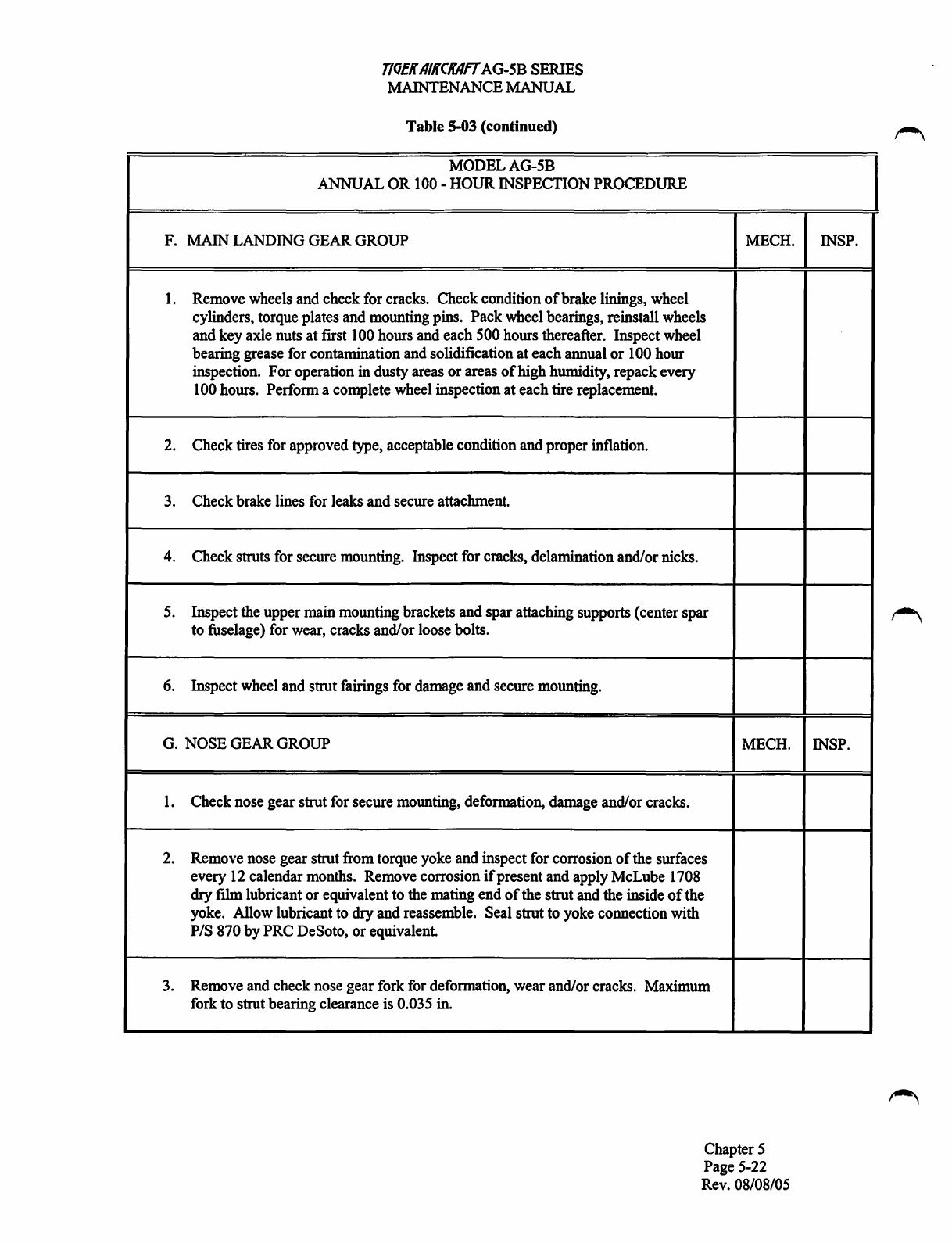
F.
MAIN
LANDING
GEAR
GROUP
MECH.
1.
Remove
wheels
and
check
for
cracks. Check condition
of
brake linings, wheel
cylinders, torque plates
and
mounting pins. Pack wheel bearings, reinstall wheels
and
key
axle
nuts at
frrst
100
hours
and
each 500
hours
thereafter. Inspect
wheel
bearing grease
for
contamination
and
solidification at each annual or
100
hour
inspection. For operation in dusty areas or areas
of
high humidity, repack every
100
hours. Perform a complete wheel inspection at each tire replacement.
2.
Check tires
for
approved
type,
acceptable condition
and
proper inflation.
3.
Check brake lines
for
leaks
and secure attachment.
4.
Check struts
for
secure mounting. Inspect
for
cracks, delamination and/or
nicks.
5.
Inspect
the
upper
main
mounting brackets
and
spar attaching supports (center spar
to
fuselage)
for
wear,
cracks and/or
loose
bolts.
6.
Inspect
wheel
and
strut fairings
for
damage
and
secure mounting.
G.
NOSE
GEAR
GROUP
MECH.
1.
2.
3.
Check nose gear strut
for
secure mounting, deformation,
damage
and/or cracks.
Remove
nose
gear strut
from
torque
yoke
and
inspect
for
corrosion
of
the
surfaces
every
12
calendar
months.
Remove
corrosion
if
present and apply McLube
1708
dryfilm lubricant or equivalent
to
the
mating
end
of
the strut
and
the
inside
of
the
yoke.
Allow lubricant
to
dryand reassemble.
Seal
strut
to
yoke
connection with
PIS
870
by
PRC
DeSoto, or equivalent.
Remove
and
check
nose
gear
fork
for
deformation, wear and/or cracks. Maximum
fork
to strut bearing clearance
is
0.035
in.
Chapter 5
Page
5-22
Rev.
08/08/05
INSP.
INSP.

T/QfR
AIRCRAfT
AG-5B SERIES
N.UUNTENANCE~AL
Table S-03 (continued)
MODELAG-5B
ANNUAL OR 100 -HOUR INSPECTION PROCEDURE
G. NOSE GEAR GROUP (continued) MECH.
4.
Grease fork and friction dampener, assemble to strut and tighten to 10-22 lb. drag
to axle. (Reference Chapter 32)
5. Remove nose wheel, clean, check for cracks, inspect and repackbearings,
reinstall wheel and safety axle at frrst 100 hours and each 500 hours thereafter.
Inspect wheel bearing grease for contamination and solidification at each annual
or
100 hour inspection. For operation in dusty areas
or
areas
of
high humidity,
repack every 100 hours. Perform a complete wheel inspection at tire replacement.
6.
Inspect nose wheel for cracks, corrosion and/or loose
or
broken bolts.
7.
Check tire for approved type, acceptable condition and proper inflation.
8. Check wheel fairing for damage and secure mounting.
H. OPERATIONAL INSPECTION MECH.
1.
2.
3.
4.
5.
Check brake and parking brake operation.
Check fuel primer operation and lines for leaks.
Check electric pump operation.
Check fuel pressure.
Check starter for proper operation.
Chapter 5
Page 5-23
Rev. 08/08/05
INSP.
INSP.
H.
T/QEK
AIKCKAfT
AG-5B
SERIES
MAINTENANCE
MANUAL
Table 5-03 (continued)
MODELAG-5B
ANNUAL
OR
100
-HOUR INSPECTION
PROCEDURE
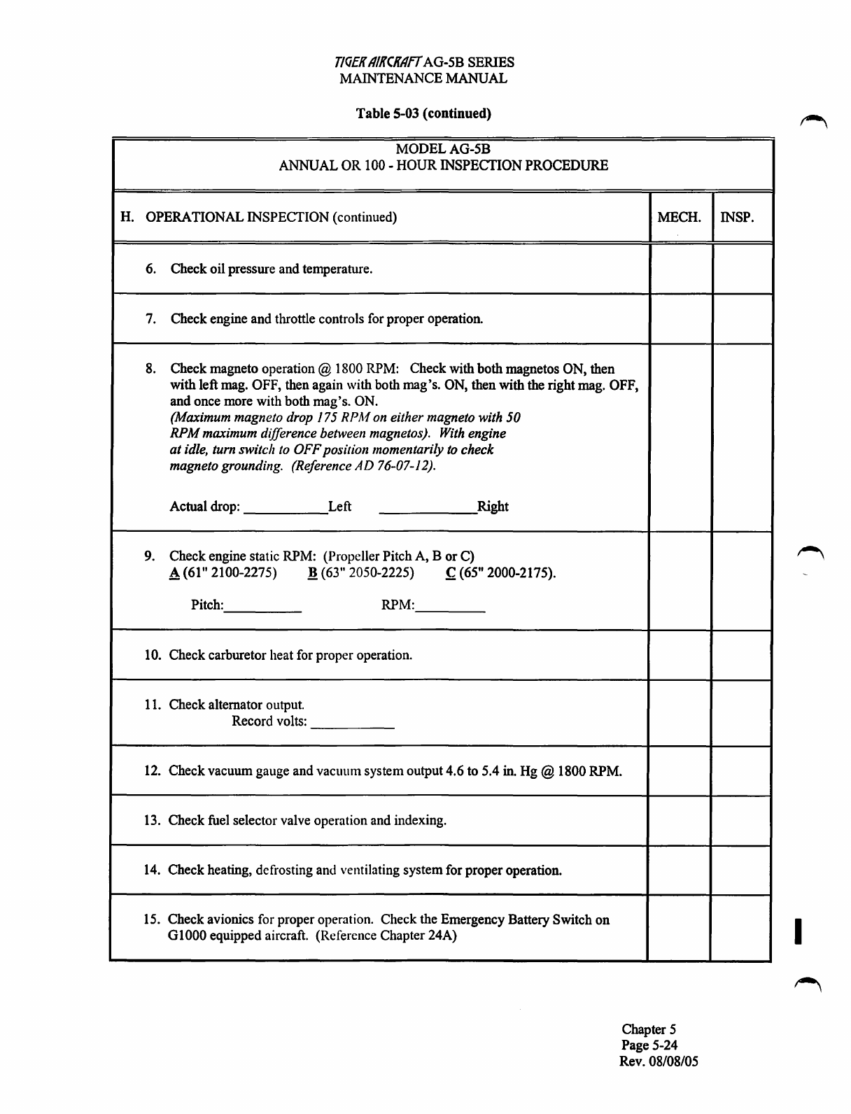
OPERATIONAL INSPECTION (continued)
6.
Check oil pressure and temperature.
7.
Check engine and throttle controls
for
proper operation.
8.
Check magneto operation @
1800
RPM:
Check with both magnetos
ON,
then
MECH.
with left
mag.
OFF,
then
again with both mag's.
ON,
then with
the
right
mag.
OFF,
and once
more
with both mag's.
ON.
(Maximum magneto drop 175
RP/11
on either magneto with
50
RPM
maximum difference between magnetos).
With
engine
at
idle, turn switch to OFFposition momentarily
to
check
magneto grounding. (Reference
AD
76-07-12).
Actual
drop:
Left Right
9. Check engine static
RPM:
(Propeller Pitch
A,
B or
C)
A(61" 2100-2275)
.!!
(63"
2050-2225)
~
(65"
2000-2175).
Pitch:
RPM:
10.
Check carburetor heat
for
proper operation.
11.
Check alternator
output.
Record
volts:
12.
Check vacuum gauge and vacuum system output 4.6
to
5.4
in.
Hg@
1800
RPM.
13.
Check
fuel
selector valve operation
and
indexing.
14.
Check heating, defrosting
and
ventilating system
for
proper operation.
15.
Check avionics
for
proper operation. Check
the
Emergency Battery Switch on
G
1000
equipped aircraft. (Reference Chapter
24A)
Chapter 5
Page
5-24
Rev.
08/08/05
INSP.
I
TJQEK
AIKCKAff
AG-5B SERIES
MAThiTENANCEMANUAL
Table 5-03 (continued)
MODELAG-5B
ANNUAL OR
100-
HOUR INSPECTION PROCEDURE
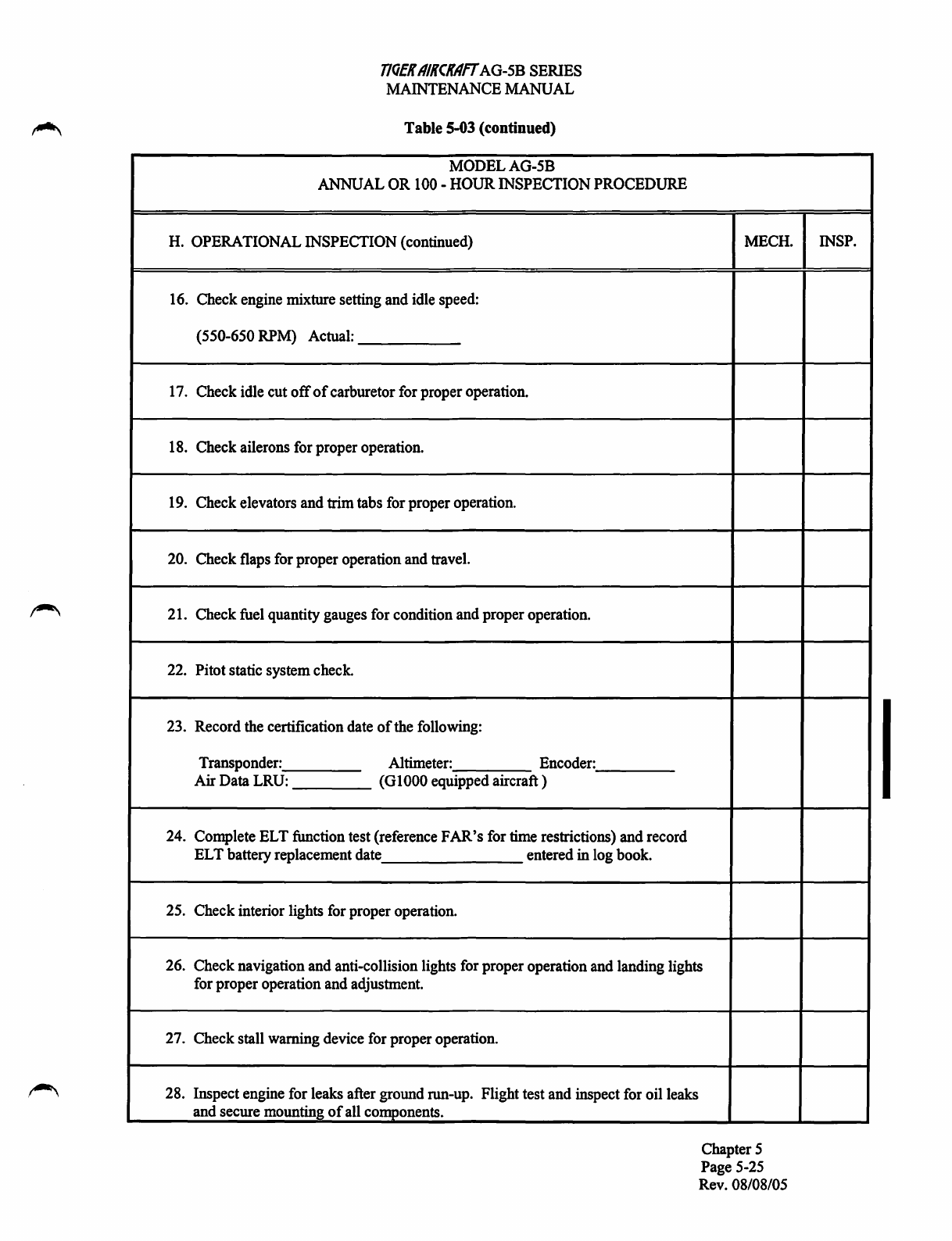
H. OPERATIONAL INSPECTION (continued)
16. Check engine mixture setting and idle speed:
(550-650 RPM) Actual:
17. Check idle cut
off
of
carburetor for proper operation.
18. Check ailerons for proper operation.
19. Check elevators and trim tabs for proper operation.
20. Check flaps for proper operation and travel.
21. Check fuel quantity gauges for condition and proper operation.
22. Pitot static systemcheck.
23. Record the certification date
of
the following:
Transponder: Altimeter: Encoder:
Air Data LRU: (G1000 equipped aircraft)
24. Complete ELT function test (reference
FAR's
for time restrictions) and record
ELT battery replacement date entered inlog book.
25. Check interior lights for proper operation.
MECH.
26. Check navigation and anti-collision lights for proper operation and landing lights
for proper operation and adjustment.
27. Check stall warning device for properoperation.
28. Inspect engine for leaks after ground run-up. Flight test and inspect for oil leaks
and secure mounting
of
all components.
Chapter 5
Page 5-25
Rev. 08/08/05
INSP.

I.
1.
2.
3.
4.
5.
6.
T/QfK
AIKCKAff
AG-5B SERIES
N.UUNTENANCE~AL
Table
5-03 (continued)
MODELAG-5B
ANNUAL
OR
100-
HOURINSPECTION PROCEDURE
GENERAL
Aircraft cleaned and serviced.
Aircraft conforms to
TC
Data
Sheet
All FAA Airworthiness Directives complied with.
All Service Letters and Bulletins complied with.
Checked for proper and complete Pilots Operating Handbook (with AFM).
Aircraftpapers in proper order. Make log book entry.
Minimum required documents:
a. Registration
b.Airworthiness Certification
c. POH with AFM (including weight and balance records and equipment list.)
d. Log Books for Aircraft, Engine and Propeller
MECH.
Chapter 5
Page 5-26
Rev. 08/08/05
INSP.
Table of contents
Other Tiger Aircraft Aircraft manuals

Popular Aircraft manuals by other brands


Cessna
Cessna 172 Skyhawk SERIES Ownersmanual

Pipistrel
Pipistrel Sinus 503 Flight and maintenance manual

Aerospool
Aerospool WT-9 Dynamic Technical description and operating instructions

Ozone
Ozone Swift 2 Pilot's manual

HPH
HPH Glasflugel 304S Technical Description, Operating, Maintenance and Repair Manual

iKarus
iKarus C42 Pilot operating handbook


