TIGIEFFE AIRO A Series User manual

PIATTAFORME AEREE SEMOVENTI
SELF-PROPELLED WORK-PLATFORMS
PLATES-FORMES DE TRAVAIL AUTOMOTRICES
SELBSTFAHRENDE HUBARBEITSBÜHNEN
PLATAFORMAS ELEVADORAS AUTOPROPULSADAS
ZELFRIJDENDE HOOGWERKERS
SJÄLVGÅENDE ARBETSPLATTFORMAR
SAMOKRETNE RADNE PLATFORME
“A” SERIES
A10 A12 A13 J
USE AND MAINTENANCE MANUAL
- ENGLISH -
AIRO is a division of TIGIEFFE SRL
Via Villasuperiore, 82 -42045 Luzzara (RE) ITALIA-
+39-0522-977365 -+39-0522-977015
WEB: www.airo.it
023.20.UEM-EN
2015-00

Use and Maintenance Manual Self-propelled aerial platforms Page 2
Tigieffe thanks you for purchasing a product of its range, and invites you to read this manual. Here you can find all the
necessary information for a correct use of the purchased machine; therefore, you are advised to follow the instructions
carefully and to read the manual thoroughly. The manual should be kept in a suitable place where no damage can occur
to it. The content of this manual may be modified without prior notice and further obligations in order to add changes and
improvements to the units already delivered. No reproduction or translation may take place without the written
permission of the owner. Contents:
1. INTRODUCTION.......................................................................................................................... 4
1.1 Legal aspects.............................................................................................................................................4
1.1.1 Delivery of the unit....................................................................................................................................... 4
1.1.2 Declaration of commissioning, first inspection, further periodical inspections and transfers of ownership.. 4
1.1.2.1 Declaration of commissioning and first inspection....................................................................................... 4
1.1.2.2 Further periodical inspections ..................................................................................................................... 5
1.1.2.3 Transfers of Ownership............................................................................................................................... 5
1.2 Intended use..............................................................................................................................................5
1.3 Description of the unit..............................................................................................................................5
1.4 Control stations.........................................................................................................................................6
1.5 Power supply.............................................................................................................................................6
1.6 Identification..............................................................................................................................................7
1.7 Location of main components .................................................................................................................8
2TECHNICAL FEATURES OF STANDARD MACHINES.............................................................. 9
3SAFETY PRECAUTIONS ...........................................................................................................11
3.1 Power supply...........................................................................................................................................11
3.2 Work and maintenance rules .................................................................................................................11
3.3 Safety rules..............................................................................................................................................12
3.3.1 General...................................................................................................................................................... 12
3.3.2 Handling .................................................................................................................................................... 12
3.3.3 Operating procedures................................................................................................................................ 14
3.3.4 Wind speed according to Beaufort table.................................................................................................... 15
4INSTALLATION AND PRELIMINARY CHECKS........................................................................19
4.1 Before using the machine ......................................................................................................................19
5GENERAL USE INSTRUCTIONS...............................................................................................20
5.1 Platform control panel............................................................................................................................20
5.1.1 Drive and steering ..................................................................................................................................... 22
5.1.1.1 Drive.......................................................................................................................................................... 22
5.1.1.2 Steering..................................................................................................................................................... 22
5.1.2 Platform positioning.................................................................................................................................. 23
5.1.2.1 Scissors lifting/lowering (first boom).......................................................................................................... 23
5.1.2.2 Second boom lifting/lowering .................................................................................................................... 23
5.1.2.3 Jib lifting/lowering (A13 J) ......................................................................................................................... 23
5.1.2.4 Telescopic boom extraction/retraction....................................................................................................... 23
5.1.2.5 Turret orientation (rotation)........................................................................................................................ 23
5.1.2.6 Platform rotation........................................................................................................................................ 24
5.1.2.6.1 Platform rotation A10 and A12 (OPTIONAL)............................................................................................. 24
5.1.2.6.2 Platform rotation A13 J.............................................................................................................................. 24
5.1.2.7 Platform levelling....................................................................................................................................... 24
5.1.3 Other functions of the platform control panel............................................................................................. 25
5.1.3.1 Selection of electric/thermic propulsion (models “EB”, “ED”) (R)............................................................... 25
5.1.3.2 Heat engine starting key ( models “EB”, “ED”) (T)..................................................................................... 25
5.1.3.3 Manual horn (H) ........................................................................................................................................ 25
5.1.3.4 Emergency STOP button (I)...................................................................................................................... 25
5.1.3.5 Fault warning light (L)................................................................................................................................ 25
5.1.3.6 Overload warning light (M) ........................................................................................................................ 26
5.1.3.7 Voltmeter (N)............................................................................................................................................. 26
5.1.3.7.1 Standard voltmeter.................................................................................................................................... 26

Use and Maintenance Manual Self-propelled aerial platforms Page 3
5.1.3.7.2 Optional voltmeter ..................................................................................................................................... 26
5.1.3.8 Fuel level indicator (OPTIONAL for models “ED” and “EB”)...................................................................... 26
5.2 Ground control station and electric central unit ..................................................................................27
5.2.1 Ground control station............................................................................................................................... 27
5.2.1.1 On-off key and control station selector...................................................................................................... 28
5.2.1.2 Emergency stop button ............................................................................................................................. 28
5.2.1.3 Warning light: machine on......................................................................................................................... 28
5.2.1.4 Platform control levers............................................................................................................................... 28
5.2.1.5 Battery charger light .................................................................................................................................. 29
5.2.2 Electric power unit on the ground.............................................................................................................. 29
5.3 Platform access.......................................................................................................................................30
5.4 Start-up.....................................................................................................................................................30
5.4.1 Diesel engine start-up (“ED” models)........................................................................................................ 30
5.4.2 Petrol motor start-up (“EB” models)........................................................................................................... 31
5.5 Machine stop ...........................................................................................................................................32
5.5.1 Normal stop............................................................................................................................................... 32
5.5.2 Emergency stop ........................................................................................................................................ 32
5.5.3 Diesel engine stop (“ED” models).............................................................................................................. 32
5.5.4 Petrol engine stop (“EB” models) .............................................................................................................. 33
5.6 Emergency manual controls ..................................................................................................................34
5.7 Socket for electric tool connection and battery charger powering ....................................................35
5.8 Fuel level and re-fuelling (models “ED”, “EB”) ....................................................................................35
5.9 End of work..............................................................................................................................................35
6HANDLING AND CARRYING.....................................................................................................36
6.1 Handling...................................................................................................................................................36
6.2 Carrying....................................................................................................................................................37
6.3 Emergency towing ..................................................................................................................................38
7MAINTENANCE..........................................................................................................................39
7.1 Machine cleaning ....................................................................................................................................39
7.2 General maintenance..............................................................................................................................40
7.2.1 Various adjustments.................................................................................................................................. 41
7.2.2 Greasing.................................................................................................................................................... 42
7.2.3 Hydraulic circuit oil level check and change.............................................................................................. 43
7.2.4 Suction filter replacement.......................................................................................................................... 43
7.2.5 Turret rotation reduction gear oil level check and change (traditional rotation system)............................. 44
7.2.6 Traction reduction gear oil level check and change .................................................................................. 45
7.2.7 Turret rotation clearance adjustment (traditional rotation system)............................................................. 46
7.2.8 Telescopic boom sliding blocks clearance adjustment.............................................................................. 46
7.2.9 Platform rotation clearance adjustment..................................................................................................... 47
7.2.10 Inclinometer adjustment ............................................................................................................................ 48
7.2.11 Adjustment of the overload controller (load cell) ....................................................................................... 50
7.2.12 Operation check of microswitches M1....................................................................................................... 52
7.2.13 Operation check of dead-man pedal safety system .................................................................................. 52
7.2.14 Starter battery for models “EB” and “ED” .................................................................................................. 52
7.2.14.1 Starter battery maintenance...................................................................................................................... 52
7.2.14.2 Starter battery recharge ............................................................................................................................ 52
7.2.15 “DRIVE” battery......................................................................................................................................... 53
7.2.15.1 General instructions for DRIVE battery ..................................................................................................... 53
7.2.15.2 DRIVE battery maintenance..................................................................................................................... 53
7.2.15.3 Battery charger: DRIVE battery recharge.................................................................................................. 54
7.2.15.4 Battery charger: fault report....................................................................................................................... 55
7.2.16 Battery replacement .................................................................................................................................. 55
8MARKS AND CERTIFICATIONS................................................................................................56
9CONTROL REGISTER ...............................................................................................................56

Use and Maintenance Manual Self-propelled aerial platforms Page 4
1. INTRODUCTION
This Use and Maintenance Manual provides general instructions concerning the complete range of units indicated on the
cover. Therefore the description of their components, as well as control and safety systems, may include parts not
present on your unit since supplied on request or not available. In order to keep pace with the technical development
AIRO-Tigieffe s.r.l. reserves the right to modify the product and/or the use and maintenance manual at any time without
updating the units already delivered.
1.1 Legal aspects
1.1.1 Delivery of the unit
Within EU (European Union) member countries the machine is delivered complete with:
-Use and Maintenance manual in your language;
-CE mark applied on the unit;
-CE conformity declaration.
It is to be noted that the Use and Maintenance Manual is an integral part of the machine and a copy of this, together
with copies of the documents certifying that the periodical checks have been carried out, must be kept on board in its
suitable container. In the event of a transfer of property the machine must always be provided with its use and
maintenance manual.
1.1.2 Declaration of commissioning, first inspection, further periodical inspections and transfers of
ownership
The legal obligations of the owner of the machine vary according to the country of commissioning. It is therefore
recommended to inquiry about the procedures in force in your country from the boards responsible for industrial safety.
This manual contains a final section called "Check register" for a better filing of documents and recording of any
modifications.
1.1.2.1 Declaration of commissioning and first inspection
In ITALY the owner of the Aerial Platform must notify the use of the unit to the local competent ISPESL (National Institute
for the prevention of accidents at the workplace) and submit it to periodical compulsory inspections. The first one of
these inspections is carried out by ISPESL, while the following ones by the territorial inspection boards (ASL/USL or
ARPA). The inspections are on a payment basis and the machine owner will be charged for them. For these inspections,
the territorial inspection boards (ASL/USL or ARPA) and ISPESL can be supported by authorized public or private
subjects. The authorized private subjects acquire the qualification of responsibles of the public service and refer directly
to the public structure that controls this function.
To declare the commissioning of the unit in Italy, send the form that is supplied together with other documents upon
machine delivery, by registered letter with advice of receipt.
Within one year of the declaration, ISPESL will assign a Serial Number and during the First Inspection will issue a
"Check booklet" indicating only the detectable data of the machine already in use or inferable from the relative User
Manual. Afterwards ISPESL will send a copy of the same booklet to the territorial inspection boards (ASL/USL or ARPA)
which will carry out the further periodical mandatory inspections (every year).

Use and Maintenance Manual Self-propelled aerial platforms Page 5
1.1.2.2 Further periodical inspections
Yearly inspections are compulsory. In Italy the owner of the Aerial Platform must apply for a periodical inspection by
sending a registered letter to the local competent inspection board (ASL/USL or ARPA) at least twenty days before the
expiry of the year from the last inspection.
NB: If a machine without a valid control document should be moved in an area outside the competence of the usual
inspection board, the owner of the machine must ask the inspection board, competent for the new territory where the
machine is to be used, for the annual inspection.
1.1.2.3 Transfers of Ownership
In case of transfer of ownership (in Italy) the new owner of the Aerial Platform must notify the ownership of the unit to the
local competent inspection board (ASL/USL or ARPA) by enclosing a copy of:
-Conformity declaration issued by the manufacturer;
-Declaration of commissioning carried out by the first owner.
-
1.2 Intended use
The machine described in this use and maintenance manual is a self-propelled aerial platform intended for lifting persons
and materials (equipment and building materials) in order to carry out maintenance, installation, cleaning, painting, de-
painting, sand-blasting, welding operations, etc.
The max. capacity allowed (which varies according to the model –see paragraph “Technical features”) is divided as
follows:
-80 Kg for each person on board;
-40 Kg for equipment;
-the remaining load is represented by the material being worked.
In any case NEVER exceed the maximum capacity allowed as indicated in paragraph "Technical features”.
All loads must be positioned inside the basket. Do not lift loads (even if complying with the maximum capacity allowed)
hanging from the platform or lifting structure.
Do not carry large-sized panels since they increase the resistance to wind force thus causing the machine to overturn.
While de-placing the unit with lifted platform do not load horizontal loads onto the platform (the operators on board must
not pull ropes, wires, etc.).
A load limiter interrupts the operation of the unit if the load on the platform exceeds by 25% the rated load (see chapter
"general use instructions”).
The unit cannot be used in areas where road vehicles operate. Always surround the working area by means of suitable
signs when the unit is used in public areas.
Do not use the machine to tow trucks or other vehicles.
1.3 Description of the unit
The machine described in this use and maintenance manual is a self-propelled aerial platform equipped with:
-motorized chassis equipped with wheels;
-hydraulically driven rotating turret;
-articulated boom operated by hydraulic cylinders (the number of articulations and cylinders varies according to
machine model);
-operator platform (the max. capacity varies according to the model - see chapter "Technical features”).
The chassis is motorised to allow the machine to move (see "General use instructions"). On two-driving wheel models
the chassis is equipped with two rear driving wheels and two front idle steering wheels. On four-driving wheel models the
chassis is equipped with two rear driving wheels and two front driving and steering wheels. All driving wheels are

Use and Maintenance Manual Self-propelled aerial platforms Page 6
equipped with hydraulic parking brakes, positive logic type (when drive controls are released brakes are automatically
activated).
The hydraulic cylinders which move the articulated structure (except for the basket cylinder rotation and boom inclination
sensor cylinder) are provided with over-centre valves directly flanged on the same. These devices allow the booms to
remain in position even if one of the supply tubes accidentally breaks.
The platform is equipped with guard-rails and toe-boards of a prescribed height (the height of the guard-rails is 1100
mm; the height of the toe-boards is 150 mm).
1.4 Control stations
The machine is equipped with two control stations:
-at platform for normal use of the unit;
-at turret (or at ground) for emergency controls to recover or stop the unit in emergency situations. The on-ground
control post is also equipped with a key-selector to select the control post and to start the unit.
1.5 Power supply
The machines can be powered by:
-an electric-hydraulic system composed of rechargeable accumulators and electric pump;
-a heat engine (Diesel engine models are identified by the abbreviation “-D”; petrol engine models are identified by
the abbreviation “-B”);
-a bi-fuel (electric/thermic) system (bi-fuel Electric/Diesel models are identified by the abbreviation “ED”; bi-fuel
Electric/Petrol models are identified by the abbreviation “EB”).
In any case both the hydraulic and the electric systems are equipped with all necessary protections (see electric and
hydraulic circuit diagrams annexed to this manual).
Do not use the machine for purposes different from those it was intended for.
If disposal of the unit is necessary, comply with current local regulations.
Use and Maintenance Manual Self-propelled aerial platforms Page 7
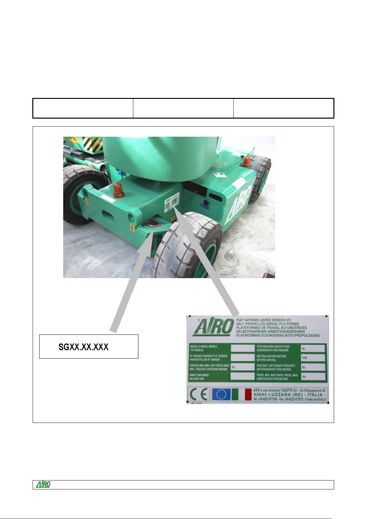
1.6 Identification
In order to identify the machine, when spare parts and service are required, always mention the information given in the
serial number plate. Should this plate (as well as the various stickers applied on the unit) be lost or illegible, it is to be
replaced as soon as possible. In order to identify the machine when no plate is available the serial number is also
stamped on the chassis. To locate the plate and the stamp of the serial number, see the following picture. The main data
of the machine to which this book refers are indicated in the following boxes:
Model.................................…………..
Chassis:..................................………...
Year:...................................…………...
Fig.1
Fig.1

Use and Maintenance Manual Self-propelled aerial platforms Page 8
1.7 Location of main components
Below is a diagram showing the machine and its components.
Fig.2
1) Control panel;
2) Electric central unit;
3) Hydraulic central unit;
4) Hydraulic drive motors;
5) Turret rotation hydraulic motor;
6) 220V socket;
7) Bubble level for visual check of
machine levelling;
8) Lifting cylinders;
9) Battery;
10) Power steering;
11) Inclinometer;
12) Heat engine fuel tank;
13) Load limiter;
14) Turntable;
15) Control device for electric
system isolation (electric
machines –E and electro/diesel
ED only).

Use and Maintenance Manual Self-propelled aerial platforms Page 9
2TECHNICAL FEATURES OF STANDARD MACHINES
DESCRIPTION
A10 E
A12 E
A12 EB
A12 ED
A13 JE
A13 JED
Max. working height - m -
9,9
12
12
12
13.1
13.1
Max. walking surface height - m -
7.9
10
10
10
11.1
11.1
Max. outreach from turntable centre - m -
4.5
6.3
6.3
6.3
8.1
8.1
Turret rotation (not continuous) - degrees -
360
360
360
360
360
360
Platform rotation - degrees -
140 (OPT)
140 (OPT)
140 (OPT)
140 (OPT)
140
140
Max. platform dimensions - mm -
800x1360
800x1360
800x1360
800x1360
800x1360
800x1360
Max. capacity - Kg -
200 (*)
200 (*)
200 (*)
200 (*)
200 (*)
200(*)
Max. No. of people on platform
2
2
2
2
2
2
Machine weight (unloaded) - Kg -
3000
3900 (*)
4120 (*)
4140 (*)
5400 (*)
5640 (*)
Max. load on each wheel - Kg -
1360
1740
1830
1840
2380
Volume - m3 -
12.4
11.9
11.9
11.9
14.9
14.9
Max. hydraulic pressure - bar -
210
210
210
210
230
210
Tyre dimensions - mm -
Ø 584x324
Ø 584x324
Ø 584x324
Ø 584x324
Ø 584x324
Ø 584x324
Tyre type
23x10-12
23x10-12
23x10-12
23x10-12
23x10-12
23x10-12
Max. operating temperature - °C -
+50°
+50°
+50°
+50°
+50°
+50°
Min. operating temperature - °C -
-5°
-5°
-5°
-5°
-5°
-5°
Stability limits:
Longitudinal inclination - degrees -
2°
2°
2°
2°
4°
4°
Transversal inclination - degrees -
2°
2°
2°
2°
4°
4°
Max. wind force (**) - m/s -
12.5
12.5
12.5
12.5
12.5
12.5
Battery power
Battery voltage and capacity - V/Ah -
48/325
48/325
48/325
48/325
48/325
48/325
Battery weight - Kg -
2 x 220
2 x 220
2 x 220
2 x 220
2 x 220
2 x 220
Single-phase battery charger - V/A -
48/40
48/40
48/40
48/40
48/40
48/40
Max. power absorbed by battery charger - A -
15
15
15
15
15
15
Max. capacity - KW -
4.5
4.5
4.5
4.5
4.5
4.5
Power voltage motor 1 - V -
48
48
48
48
48
48
Max. absorbed current - A -
160
160
160
160
160
160
Max. drive speed - m/s -
1.1
1.1
1.1
1.1
1.1
1.1
Min. drive speed - m/s -
0.2
0.2
0.2
0.2
0.2
0.2
Oil tank capacity - l -
40
40
40
40
40
40
Max. gradeability - % -
25
25
25
25
25
25
Petrol engine (model EB)
Engine type
----
----
KOHLER
CH15
----
----
----
Max. engine power - kW -
----
----
11.2
----
----
----
Starter battery - V/Ah -
----
----
12/55
----
----
----
Max. drive speed - m/s -
----
----
1.1
----
----
----
Min. drive speed - m/s -
----
----
0.2
----
----
----
Oil tank capacity - l -
----
----
67
----
----
----
Petrol tank capacity - l -
----
----
5
----
----
----
Max. gradeability - % -
----
----
25
----
----
----

Use and Maintenance Manual Self-propelled aerial platforms Page 10
DESCRIPTION
A10 E
A12 E
A12 EB
A12 ED
A13 JE
A13 JED
Diesel engine (model ED)
Diesel engine type
----
----
----
HATZ 1B40
----
HATZ 1B40
Max. engine power - KW -
----
----
----
6.6
----
6.6
Starter battery - V/Ah -
----
----
----
12/55
----
12/55
Max. drive speed - m/s -
----
----
----
1.1
----
1.1
Min. drive speed - m/s -
----
----
----
0.2
----
0.2
Oil tank capacity - l -
----
----
----
67
----
67
Diesel oil tank capacity - l -
----
----
----
5
----
5
Max. gradeability - % -
----
----
----
25
----
25
(*) In some cases different limits can be fixed. It is recommended to comply with the data shown on the machine plate.
(**) Wind speeds higher or equal to 12.5 m/s indicate that the machines can also be used outside; Wind speeds equal to 0 m/s indicate that the
machines can be used INSIDE ONLY.
Noise tests have been carried out under the most unfavourable conditions to study the effects on the operator.
-ELECTRICAL MODELS: The level of acoustic pressure weighed (A) at work places does not exceed 70dB(A).
-MODELS WITH HEAT ENGINE: The level of acoustic pressure weighed (A) at work places does not exceed 107dB(A); the level of acoustic
pressure at ground control station does not exceed 87dB(A); the level of acoustic pressure at platform control station does not exceed
87bD(A).
As to vibrations in ordinary working conditions:
-- the rms. value weighed according to acceleration frequency relevant to the upper limbs is lower than 2.5 m/sec2;
-- the rms. value weighed according to acceleration frequency relevant to the body is lower than 0.5 m/sec2.
Use and Maintenance Manual Self-propelled aerial platforms Page 11
3SAFETY PRECAUTIONS
3.1 Power supply
The electric and hydraulic circuits are provided with safety devices, calibrated and sealed by the manufacturer.
Do not tamper with and modify the calibration of any component of the electric and hydraulic system.
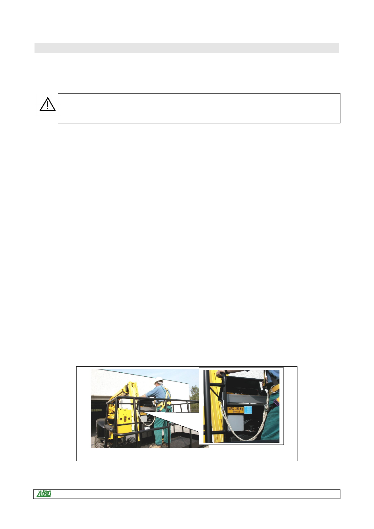
3.2 Work and maintenance rules
-Always wear personal protective clothes according to current regulations concerning industrial health and safety (in
particular, helmet and safety harness are COMPULSORY. See picture below).
-The machine must be used only in areas well lit up, checking that the ground is flat and firm. The machine may not
be used if the lighting conditions are not sufficient.
-Do not use the thermic power (Diesel or Petrol engine) indoors or in insufficiently ventilated areas.
-Before using the machine check its integrity and conservation state.
-During maintenance operations do not dispose of any waste materials in the environment, but comply with current
regulations.
-Do not carry out any service or maintenance operations when the machine is connected to the power supply. Follow
the instructions given in the following paragraphs.
-For the maintenance of the heat engine (Diesel or Petrol engine) supplement the instructions given in this manual
with those given in the heat engine manual.
-Do not approach the electric and hydraulic system components with sources of heat or flames.
-The platform is intended for people carriage; therefore, it is necessary to comply with the current local regulations
relevant to this class of machines.
-Do not increase the max. allowed height by means of scaffolds, ladders or other.
-Do not use the machine as a crane.
-Do not use the machine as a hoist and/or lift.
-Protect the unit (in particular the platform control switchboard) and the operator when working in adverse
environmental conditions (painting, de-painting, sand-blasting, washing, etc.).
-It is forbidden to the unit in case of severe weather conditions (rainstorms with wind exceeding the limit speed
indicated in chapter "Technical features”).
-In the event of rain or in parking condition always protect the on-platform control panel by means of the specially
provided cap.
-Do not use the machine in areas where risks of fire or explosion exist.
-Do not use pressurized water jets (high-pressure cleaners) to wash the machine.
Fig.3

Use and Maintenance Manual Self-propelled aerial platforms Page 12
3.3 Safety rules
3.3.1 General
Only adults, after carefully reading this manual, are allowed to use the machine.
Use the machine at a distance of at least 5 metres from high-tension lines (in any case not in
proximity to live elements).
Use the machine according to the capacity values indicated in the technical features section. The
max. No. of people allowed on the platform and the capacity are specified on the identification plate.
It is absolutely forbidden to load persons, tools and building materials on the platform when it is not
in access position.
Do NOT use the framework of the platform or any of its elements for grounding connection while
welding on platform.
It is the machine owner and/or safety manager’s responsibility to check that the operators have
been thoroughly trained in the use of the machine.
It is the machine owner and/or safety manager’s responsibility to check that the maintenance and
repair operations are carried out by skilled personnel.
3.3.2 Handling
Before any movement make sure that the machine plugs are disconnected from the power source.
Always check the cable position during handling if the machine is powered with a 220V electric
pump.
In order to avoid any instability, use the machine on regular and firm grounds. Before lifting the
platform check the platform level through the spirit level which is located on the platform. To
prevent the machine from overturning, comply with the max. gradeability values indicated in the
technical features section under paragraph "Stability limits". However, movements on inclined
grounds are to be carried out with the utmost caution.
As soon as the platform is lifted (the tolerance varies according to the model) the safety drive speed
is automatically activated.
Drive the unit with lifted platform only on flat grounds, verifying the absence of holes or steps on
the floor and bearing in mind the overall dimensions of the unit.
While driving the unit with lifted platform the operators are not allowed to place horizontal loads
onto the platform (operators on board must not pull ropes, wires, etc.).
The machine must not be used directly for road transport. Do not use it for material transport (see
paragraph 1.2 “Intended use”).
Check that in the operating area there are not obstacles or other dangerous elements.
Pay particular attention to the area above the machine during lifting to avoid any crushing and
collisions.
Use and Maintenance Manual Self-propelled aerial platforms Page 13
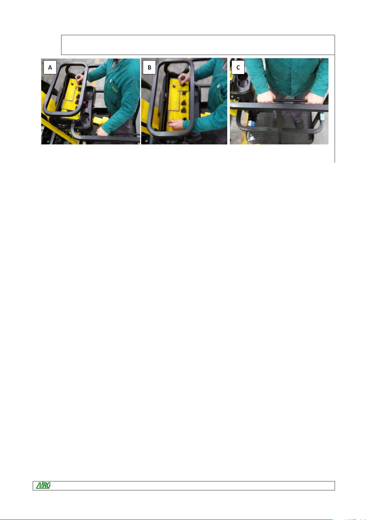
Mind your hands throughout machine operation. The driver should keep his hands as shown in
picture A or B, while operators on board should keep their hands as shown in picture C.
Fig.4

Use and Maintenance Manual Self-propelled aerial platforms Page 14
3.3.3 Operating procedures
The machine is equipped with a load-on-platform control system stopping the platform in case of
overloading. Platform operation can be resumed only after removing the exceeding load. Should the
audible warning device and the red light located on the platform control panel turn on, then the
machine is overloaded (see paragraph relevant to general use instructions). Remove the exceeding
load before starting operations again.
The machine is equipped with a chassis inclination control system disabling lifting operations in
case of unstable positioning. Working operations can be resumed only after placing the machine in
a steady position. Should the audible device and the red light on the platform control panel turn on,
the machine is not correctly positioned (see paragraphs relevant to general use instructions). Bring
it to safety rest position before starting operations again.
Electric power machines are equipped with a device controlling the electric system isolation. In
case of isolation loss or remote switch fault, such device (located on the chassis or on the turret –
see paragraph "Location of main components") brings the machine to a complete halt and signals
the fault by means of a continuous hissing sound.
Do not lean over the platform guard-rails. Avoid severe weather conditions and, in particular, windy
days.
During operations in public areas surround the working area by means of barriers or other suitable
signs.
Do not use the thermic power (Diesel or Petrol engine) indoors or in insufficiently ventilated areas.
Make sure that no people, apart from the operator, are in the area where the machine is operating.
While moving the platform, the operator on board should pay particular attention to avoid any
contact with the personnel on the ground.
Lift the platform only if the machine is resting on solid and horizontal surfaces.
Drive the machine with lifted platform only if the ground is solid and horizontal.
After each work session, always take the key out of the control panel and keep it in a safe place to
prevent unauthorized people from using the machine.
Always place working tools in a steady position to prevent them from falling and hurting the
operators on the ground.
Use and Maintenance Manual Self-propelled aerial platforms Page 15
3.3.4 Wind speed according to Beaufort table.
You can use the table below for a simple assessment of the wind speed. We remember that the max. limit for each
machine model is indicated in the table TECHNICAL FEATURES OF STANDARD MACHINES.
The machines for which the max. wind limit is 0 m/s must be used indoors only. These machines
cannot be used outdoors even with no wind.
Beaufort
Number
Wind
speed
(km/h)
Wind
speed
(m/s)
Description
Sea conditions
Land conditions
0
0
<0.28
Calm
Flat
Calm. Smoke rises vertically.
1
1-6
0.28–1.7
Light air
Ripples without crests.
Wind motion visible in smoke.
2
7-11
1.7–3
Light Breeze
Small wavelets. Crests of glassy
appearance, not breaking.
Wind felt on exposed skin.
Leaves rustle.
3
12-19
3–5.3
Gentle breeze
Large wavelets. Crests begin to
break; scattered whitecaps.
Leaves and smaller twigs in
constant motion.
4
20-29
5.3–8
Moderate
breeze
Small waves.
Dust and loose paper raised.
Small branches begin to move.
5
30-39
8.3-10.8
Fresh breeze
Moderate (1.2 m) longer waves.
Some foam and spray.
Smaller trees sway.
6
40-50
10.8-13.9
Strong breeze
Large waves with foam crests and
some spray.
Large branches in motion.
Whistling heard in overhead
wires. Umbrella use becomes
difficult.
7
51-62
13.9-17.2
Near gale /
moderate gale
Sea heaps up and foam begins to
streak.
Whole trees in motion. Effort
needed to walk against the
wind.
8
63-75
17.2-20.9
Fresh gale
Moderately high waves with
breaking crests forming spindrift.
Streaks of foam.
Twigs broken from trees. Cars
veer on road.
9
76-87
20.9-24.2
Strong gale
High waves (6-7 m) with dense
foam. Wave crests start to roll over.
Considerable spray.
Larger branches break off trees,
construction/temporary signs
and barricades blown over,
damage to circus tents and
canopies.
10
88-102
24.2-28.4
Whole gale /
Storm
Very high waves. The sea surface
is white and there is considerable
tumbling. Visibility is reduced.
Trees broken off or uprooted,
saplings bent and/or deformed,
poorly attached asphalt shingles
and shingles in poor condition
peel off roofs.
11
103-117
28.4-32.5
Violent storm
Exceptionally high waves.
Widespread vegetation
damage, minor damage to most
roof shingles/surfaces, gravel
may be blown from flat roofs.
12
>117
>32.5
Hurricane
Huge waves. Air filled with foam
and spray. Sea completely white
with driving spray. Visibility greatly
reduced.
Considerable and widespread
damage to vegetation, a few
windows broken, structural
damage to mobile homes and
poorly constructed sheds and
barns.
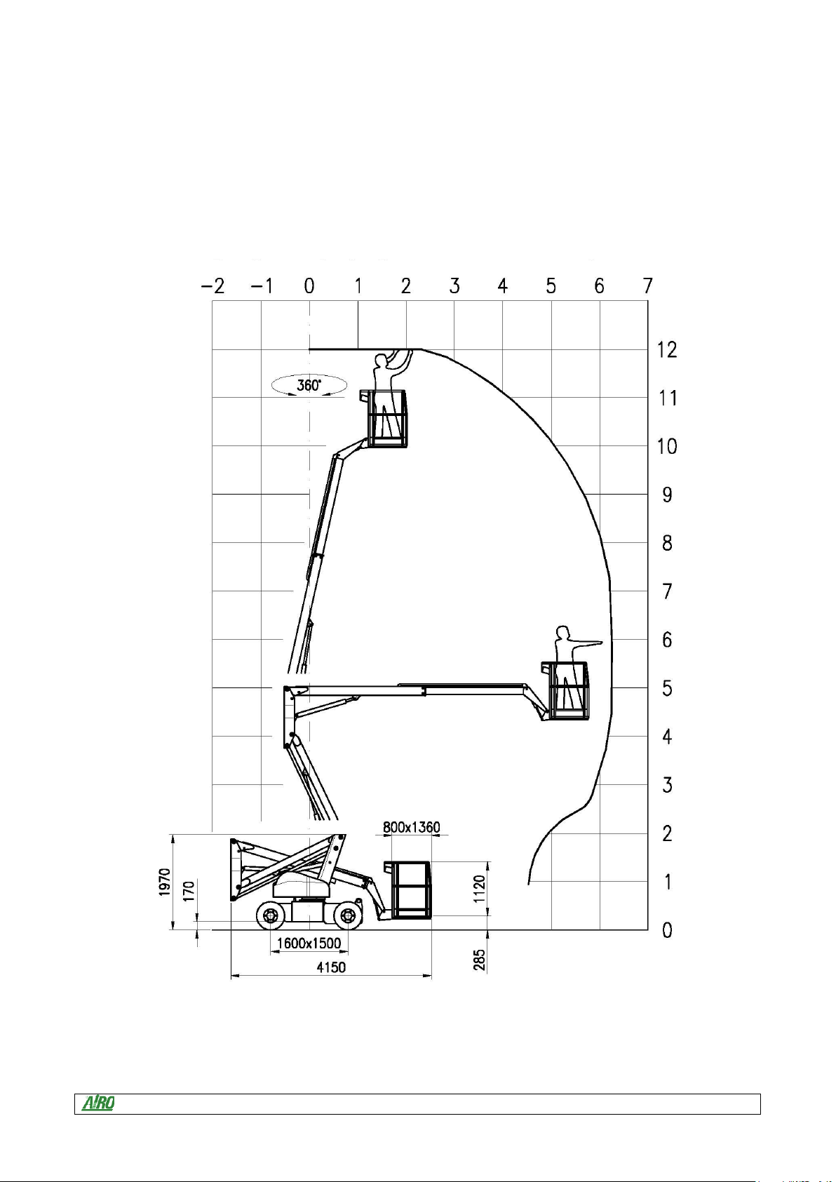
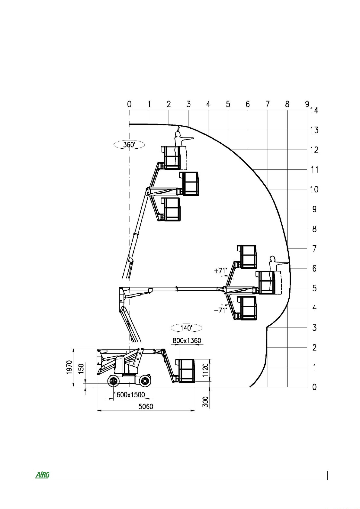
From the following pictures you can locate the action range of the platform while the chassis is kept in a fixed
position. Watch these pictures carefully in order to position the chassis so as to avoid any contacts with obstacles
present in the action range.
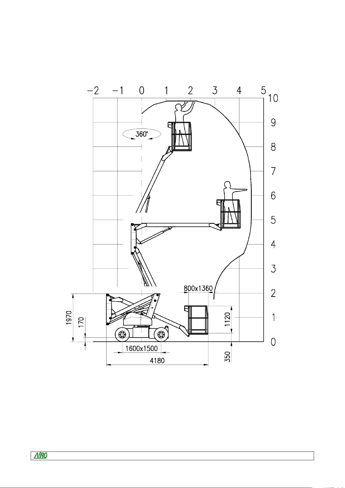
Use and Maintenance Manual Self-propelled aerial platforms Page 16
FIG.5
A10
Use and Maintenance Manual Self-propelled aerial platforms Page 17
FIG. 6
A12 E
A12 EB
A12 ED
Use and Maintenance Manual Self-propelled aerial platforms Page 18
FIG.7
A13 JE
A13 JED

Use and Maintenance Manual Self-propelled aerial platforms Page 19
4INSTALLATION AND PRELIMINARY CHECKS
The machine is supplied completely assembled, therefore it can perform all functions in full safety as provided for by the
manufacturer. No preliminary operation is required. To unload the machine, follow the instructions in paragraph “handling
and carrying”.
Place the machine onto a firm ground and with a gradeability lower than the max. allowed (see technical features
“Stability limits”). The machine is equipped with platform bubble level for visual check and an inclinometer on the chassis
(or turret) to always check machine levelling, both transversal and longitudinal.
Before using the machine read the instructions given in this manual and the concise instructions indicated on the
platform plate.
Before starting any operations verify the integrity of the unit (by means of a visual check) and read the plates indicating
the operating limits.
4.1 Before using the machine
Before using the machine the operator must always check visually that:
-the battery is completely charged;
-the oil level lies between the min. and max. value (with lowered platform);
-the machine carries out all operations in safety;
-the wheels and drive engines are properly fixed;
-the wheels are in good condition;
-the guardrails are fixed to the platform and the self-closing gates are present;
-the structure does not show clear faults (check welding of lifting structure);
-the instructions plates are perfectly readable;
-the controls are perfectly efficient both at platform and at emergency ground control station, including the “dead-
man” system.
Use and Maintenance Manual Self-propelled aerial platforms Page 20
5GENERAL USE INSTRUCTIONS
Before using the machine read this chapter thoroughly.
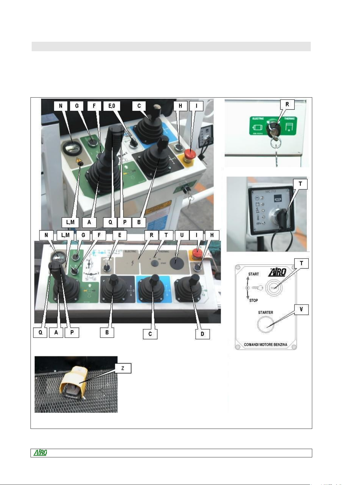
5.1 Platform control panel
Fig.8
Other manuals for AIRO A Series
3
This manual suits for next models
9
Table of contents
Other TIGIEFFE Boom Lift manuals

Popular Boom Lift manuals by other brands

Terex
Terex Genie Z-34/22N Operator's manual

Oshkosh Corporation
Oshkosh Corporation JLG X26JPLUS Operator, safety, and general maintenance manual

Terex
Terex Genie GR-20J Operator's manual

Terex
Terex Genie Z-25J Operator's manual

Skyjack
Skyjack ZB12032 operating manual

Terex
Terex Genie Z-135/70 installation instructions


