Special Limitations
SB66JRT – 0084221 5
Special Limitations
Travel with the platform raised is limited to creep speed
range. Elevating the platform is limited to firm, level
surfaces only.
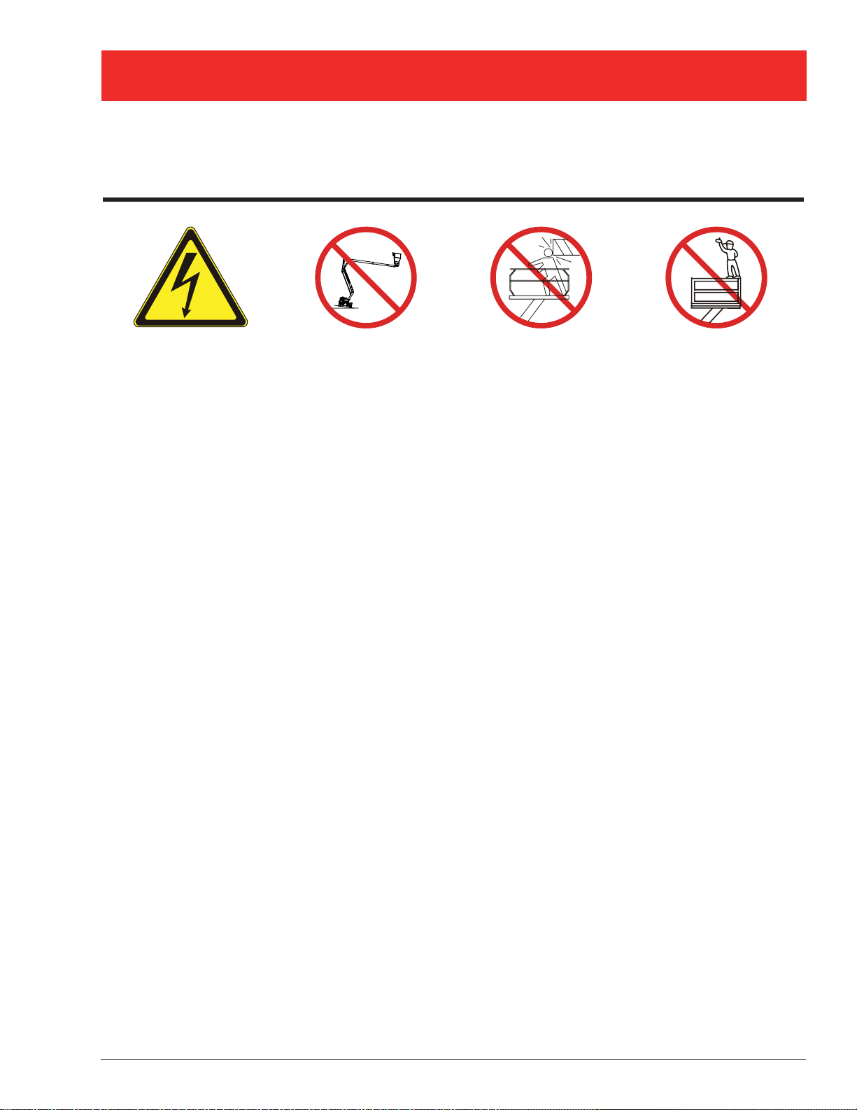
ADanger
The elevating function shall ONLY be used when the
work platform is level and on a firm surface.
The work platform is NOT intended to be driven over
uneven, rough, or soft terrain.
Platform Capacity
Twopeopleand toolsmayoccupytheplatform.The maxi-
mum platform capacity for the aerial platform is stated in
the “Specifications” on page 20.
ADanger
DO NOT exceed the maximum platform capacity or
the platform occupancy limits for this machine.
Manual Force
Manual force is the force applied by the occupants to
objects such as walls or other structures outside the
work platform.
The maximum allowable manual force is limited to 200N
(45 lbs) of force per occupant, with a maximum of 400 N
(90 lbs) for two occupants.
ADanger
DO NOT exceed the maximum amount of manual
force for this machine.
Platform Overload Sensing System
All functions are stopped from the upper and lower con-
trols, when the platform overload limit is exceeded. The
horn will sound intermittently and the platform overload
light will blink until the excess load is removed from the
platform. At that time, the machine functions are again
operational.
If the platform becomes significantly overloaded, or if an
upwardforceontheplatformexceedsapproximately2225
N(500lb), thesystemwill enterintoerrormode,stopping
all functions from the upper and lower controls. The horn
will then sound constantly and the overload light will stay
illuminated at the upper and lower controls.
The system will remain in error mode until the excess
load is removed from the platform and the emergency
stop button or start switch is cycled off and back on,
resetting the system.At that time, the machine functions
are operational.
ACaution
The emergency power system is for emergency low-
ering and stowing only. The length of time the pump
can be operated depends on the capacity of the bat-
tery. Do not use this system for normal operation.
If the platform overload sensing system is tripped while
operating the machine or if the system is in error mode
and can not be reset, the emergency power system may
still be used for emergency machine operation.
ADanger
The aerialplatformcan tipover ifit becomesunstable.
Death or serious injury will result from a tip-over ac-
cident. Do not exceed the capacity values indicated
on the platform rating placard.
The overload sensing system is not active when the
machine is being driven with the booms in the stowed
position. This allows the machine to be driven without
the system sensing an overload due to rough ground
conditions.
To eliminate repeated tripping of the system during ma-
chine operation, there is a five second delay in machine
functions following:
starting the engine.
placing the drive/boom selector switch in the boom
position when the main boom is below horizontal and
fully retracted.
removing excess load from the platform.
Beaufort Scale
Never operate the machine when wind speeds exceed
12.5 m/s (28mph) [Beaufort scale 6]. Refer to Figure 1.
•
•
•
BEAUFORT
RATING WIND SPEED GROUND CONDITIONS
m/s km/h ft/s mph
3 3,4~5,4 12,25~19,4 11.5~17.75 7.5~12.0 Papers and thin branches move, flags wave.
4 5,4~8,0 19,4~28,8 17.75~26.25 12.0~18 Dust is raised, paper whirls up, and small branches sway.
5 8,0~10,8 28,8~38,9 26.25~35.5 18~24.25 Shrubs with leaves start swaying. Wave crests are apparent in ponds
or swamps.
6 10,8~13,9 38,9~50,0 35.5~45.5 24.5~31 Tree branches move. Power lines whistle. It is difficult to open an
umbrella.
7 13,9~17,2 50,0~61,9 45.5~56.5 31.~38.5 Whole trees sway. It is difficult to walk against the wind.
Figure 1 – Beaufort Scale