TIGIEFFE AIRO A Series User manual

PIATTAFORME AEREE SEMOVENTI
SELF-PROPELLED WORK-PLATFORMS
PLATES-FORMES DE TRAVAIL AUTOMOTRICES
SELBSTFAHRENDE HUBARBEITSBÜHNEN
PLATAFORMAS ELEVADORAS AUTOPROPULSADAS
ZELFRIJDENDE HOOGWERKERS
SJÄLVGÅENDE ARBETSPLATTFORMAR
SAMOKRETNE RADNE PLATFORME
SERIES „A“
A12 JRTD A15 JRTD
USER'S MANUAL
ENGLISH TRANSLATION OF THE ORIGINAL USER MANUAL IN ITALIAN
AIRO is a division of TIGIEFFE SRL
Via Villa Superiore, 82 -42045 Luzzara (RE) ITALY -
+39-0522-977365 - +39-0522-977015
WEB: www.airo.com
057.20.UEM-EN
2020 - 01

User’s Manual – A12 JRTD A15 JRTD Series
Page 2
Review date
Description of revision
01-2010
•Manual issue.
11-2010
•Instructions for use of bio oil has been added.
•Oil temperature and oil list updated.
12-2010
•Instructions for emergency towing using an optional pump have been added.
05-2011
•Amended information on “Commissioning and first inspection, subsequent inspections and
title transfer report”.
•Additions to the Technical Data: “Total quantity of battery electrolyte”
•"Max. power" diesel engine changed and "Regulated Power" added
2013-10
•Instruction details have been added relative to harness anchoring points.
2014-09
•Added information on the maximum manual forces.
•Changed Name and Surname of CEO.
2015-01
•CE Statement of Compliance updated
•Additional instructions on hand position have been added.
2015-10
•The list of recommended hydraulic oils was updated.
•A paragraph was added stating strictly original spare parts should be used or alternatively
the approval of the manufacturer should priory obtained.
•The whole paragraph “Deboarding the platform off the ground” is new.
2015-11
•Tilt alarm operation description updated.
2018-05
•Data sheets were added with units of measurement of the international system and US unit
of measurement.
•Changed Name and Surname of CEO.
•Unified First and Second Part.
2019-07
•Statements of successful commissioning of machine in Italy description updated.
2020-01
•“OPTIONAL load control system for engines TIER4F/STAGE5” has been added.
•Regulatory references and certifying agency have been updated.

User’s Manual – A12 JRTD A15 JRTD Series
Page 3
Tigieffe thanks you for purchasing a product of its range, and reminds you to read this manual and familiarize with its contents
before using the machine. Here you can find all the necessary information for a correct use of the purchased machine; therefore,
you are advised to follow the instructions carefully and to read the manual thoroughly. Please store this manual in a safe place, but
at quick-reach in case of need. The contents of this manual may be modified as a result of any change or improvement done by the
manufacturer. The reproduction or translation of the whole manual or parts thereof is strictly forbidden without prior written approval
of the owner.
Contents:
1. INTRODUCTION................................................................................................................................................ 6
1.1. Legal mentions.................................................................................................................................................... 6
1.1.1. Handover of the machine....................................................................................................................................... 6
1.1.2. Statements of successful commissioning, first installation test, periodical functional tests and property transfers...... 6
1.1.2.1. Statements of successful commissioning carried out by the first owner. .................................................................. 6
1.1.2.2. Periodical Functional Tests.................................................................................................................................... 7
1.1.2.3. Transfers of ownership.......................................................................................................................................... 7
1.1.3. Operators training and information......................................................................................................................... 7
1.2. Tests performed before delivery......................................................................................................................... 7
1.3. Intended use........................................................................................................................................................ 7
1.3.1. Deboarding the platform off the ground.................................................................................................................. 8
1.4. Description of the machine................................................................................................................................. 8
1.5. Operator's stations.............................................................................................................................................. 9
1.6. Power supply..................................................................................................................................................... 10
1.7. Machine life, demolition and decommissioning............................................................................................... 10
1.8. Identification...................................................................................................................................................... 11
1.9. Location of main components. ......................................................................................................................... 12
2. TECHNICAL FEATURES OF THE STANDARD MACHINES. .....................................................................13
2.1. Model A12 JRTD................................................................................................................................................ 13
2.2. Model A15 JRTD................................................................................................................................................ 16
2.3. Vibrations and noise......................................................................................................................................... 19
3. SAFETY SIGNS. ..............................................................................................................................................20
3.1. Personal protective equipment (PPE)............................................................................................................... 20
3.2. General safety norms........................................................................................................................................ 20
3.3. Use instructions................................................................................................................................................ 21
3.3.1. General............................................................................................................................................................... 21
3.3.2. Handling. ............................................................................................................................................................ 21
3.3.3. Operating procedure. .......................................................................................................................................... 22
3.3.4. Wind speed according to the Beaufort scale......................................................................................................... 23
3.3.5. Ground Pressure and load-bearing capacity......................................................................................................... 24
3.3.6. High-voltage lines................................................................................................................................................ 25
3.4. Hazardous situations and/or accidents............................................................................................................ 25
4. INSTALLATION AND PRELIMINARY CHECKS...........................................................................................26
4.1. Familiarizing with the machine. ........................................................................................................................ 26
4.2. Preliminary controls.......................................................................................................................................... 26
5. OPERATING INSTRUCTIONS........................................................................................................................27
5.1. Platform control panel....................................................................................................................................... 27
5.1.1. Travelling and steering. ....................................................................................................................................... 28
5.1.2. Platform positioning movements. ......................................................................................................................... 29
5.1.2.1. Lifting/lowering of the first crank arm (pantograph). .............................................................................................. 29
5.1.2.2. Upper boom lifting/lowering. ................................................................................................................................ 30
5.1.2.3. Jib lifting/lowering................................................................................................................................................ 30
5.1.2.4. Telescopic boom extension/retraction. ................................................................................................................. 30
5.1.2.5. QUICK UP/QUICK DOWN (optional) ................................................................................................................... 30
5.1.2.6. Turret orientation (rotation). ................................................................................................................................. 30
5.1.2.7. Jib rotation (optional)........................................................................................................................................... 30
5.1.2.8. Platform rotation.................................................................................................................................................. 30

User’s Manual – A12 JRTD A15 JRTD Series
Page 4
5.1.2.9. Platform levelling................................................................................................................................................. 31
5.1.3. Other functions of the platform control panel. ....................................................................................................... 32
5.1.3.1. Manual horn........................................................................................................................................................ 32
5.1.3.2. Emergency stop button........................................................................................................................................ 32
5.1.3.3. Warning lights..................................................................................................................................................... 32
5.1.3.3.1. Green pilot lamp (ZA), operator's station enabled................................................................................................. 32
5.1.3.3.2. Red pilot lamp (ZB): warns when battery is out of charge - (Only available on electrical models)............................ 32
5.1.3.3.3. Red pilot light (ZC): diesel engine fault or low fuel. ............................................................................................... 33
5.1.3.3.4. Danger red warning light (ZD).............................................................................................................................. 33
5.1.3.3.5. Red pilot: Overload (ZE)...................................................................................................................................... 33
5.2. Ground control panel and electric control unit. ............................................................................................... 34
5.2.1. Ground control panel and electric control unit (OPTIONAL) for TIER 4 FINAL and STAGE 5 engines .................... 35
5.2.2. On-off key and control panel selector (A). ............................................................................................................ 36
5.2.3. Emergency stop button (B). ................................................................................................................................. 36
5.2.4. Diesel engine, start button (C). ............................................................................................................................ 36
5.2.5. User interface display (D). ................................................................................................................................... 37
5.2.6. MURPHY display and DPF regeneration.............................................................................................................. 37
5.2.7. Pilot light: machine ON and running..................................................................................................................... 40
5.2.8. Diesel engine, warning pilot lamps (G H L M)....................................................................................................... 40
5.2.9. Platform control levers (N O P Q R S T U)............................................................................................................ 40
5.3. Boarding the platform....................................................................................................................................... 41
5.4. Machine start..................................................................................................................................................... 41
5.4.1. Starting of the diesel engine. ............................................................................................................................... 42
5.5. Stopping the machine....................................................................................................................................... 42
5.5.1. Normal stop. ....................................................................................................................................................... 42
5.5.2. Emergency stop button........................................................................................................................................ 42
5.5.3. Stopping the diesel engine................................................................................................................................... 43
5.6. Emergency manual controls............................................................................................................................. 44
5.7. Optional socket for electric attachments.......................................................................................................... 45
5.8. Fuel level and re-fuelling (models “ED”, “D”)................................................................................................... 45
5.9. End of a work day.............................................................................................................................................. 45
6. HANDLING AND TRANSPORTATION,.........................................................................................................46
6.1. Handling, ........................................................................................................................................................... 46
6.2. Transportation................................................................................................................................................... 47
6.3. Emergency tow-away of the machine............................................................................................................... 48
6.3.1 Emergency towing the machine away (standard facility)............................................................................................. 48
6.4. Emergency towing the machine away (optional facility).................................................................................. 49
7. MAINTENANCE...............................................................................................................................................50
7.1. Machine cleaning. ............................................................................................................................................. 50
7.2. General maintenance. ....................................................................................................................................... 51
7.2.1. Adjustments........................................................................................................................................................ 52
7.2.2. Greasing............................................................................................................................................................. 53
7.2.3. Checking and changing the hydraulic circuit oil..................................................................................................... 54
7.2.3.1 Bio oils (optional)................................................................................................................................................. 55
7.2.3.2 Emptying............................................................................................................................................................. 55
7.2.3.3 Filters. ................................................................................................................................................................ 55
7.2.3.4 Washing. ............................................................................................................................................................ 55
7.2.3.5 Filling.................................................................................................................................................................. 55
7.2.3.6 Commissioning / check........................................................................................................................................ 55
7.2.3.7 Mixing................................................................................................................................................................. 56
7.2.3.8 Micro-filtration. .................................................................................................................................................... 56
7.2.3.9 Disposal.............................................................................................................................................................. 56
7.2.3.10 Topping up.......................................................................................................................................................... 56
7.2.4. Hydraulic filter replacement. ................................................................................................................................ 57
7.2.4.1. Suction filters. ..................................................................................................................................................... 57
7.2.4.2. Return filter......................................................................................................................................................... 57
7.2.5. Adjustment of the clearance of the sliding pads under the telescopic boom........................................................... 58

User’s Manual – A12 JRTD A15 JRTD Series
Page 5
7.2.6. Efficiency check of the pressure relief valve in the operating line........................................................................... 59
7.2.6.1 Pressure relief valve of the circuit of proportional movements............................................................................... 59
7.2.6.2. Pressure relief valve of the circuit of ON-OFF movements.................................................................................... 60
7.2.7. Efficiency check of the inclinometer in the turret. .................................................................................................. 61
7.2.8. Adjustment of the overload controller (load cell). .................................................................................................. 63
7.2.9. Overload controller by-pass –ONLY FOR EMERGENCY OPERATIONS. ............................................................ 64
7.2.10. Operation check of M1 micro switches................................................................................................................. 65
7.2.11. Functional check of the manning control pedal. .................................................................................................... 66
7.3. Starter battery. .................................................................................................................................................. 67
7.3.1 Battery maintenance. .......................................................................................................................................... 67
7.3.2 Starter battery recharge....................................................................................................................................... 67
7.3.3 Battery replacement. ........................................................................................................................................... 67
8. MARKS AND CERTIFICATIONS....................................................................................................................68
9. PLATES AND LABELS...................................................................................................................................69
10. CONTROL LEDGER........................................................................................................................................71
11. WIRING DIAGRAMS........................................................................................................................................86
12. HYDRAULIC DIAGRAM..................................................................................................................................93
13. FORMAT OF THE EC STATEMENT OF COMPLIANCE..............................................................................95

User’s Manual – A12 JRTD A15 JRTD Series
Page 6
1. INTRODUCTION.
This is a general manual applicable to all models stated on the cover page. Therefore, the description of the machine and its
components, as well as control and safety systems, may include parts that are not actually available on your machine depending
on model and date of purchase. In order to keep pace with the technical development, AIRO-Tigieffe s.r.l. reserves itself the right to
modify the product and/or the user's manuals as needed and without any obligation to prior updates of already existing manuals.
1.1. Legal mentions.
1.1.1. Handover of the machine.
Deliveries to any member country of the EC (European Union) are always accompanied by the following documents:
▪User's Manual in the native language of the country of use.
▪CE-plate attached to the machine
▪EC Statement of Compliance
▪Warranty certificate
▪Declaration of internal testing
Only for Italy:
▪Instruction for applying to INAIL to register the commissioning of the machine and schedule the first overhaul inspection on
INAIL webpage.
Please note: this manual is an integral part of the machine. The original manual or copy thereof must be available on board of the
machine along with the original reports (or copies thereof) of all periodical tests conducted by the user. In the event of a transfer of
ownership the machine must always be provided with its use and maintenance manual.
1.1.2. Statements of successful commissioning, first installation test, periodical functional tests and
property transfers.
The legal obligations of the owner of the machine vary according to the country of commissioning. Therefore, customers are
recommended to check on the safety procedures applicable in their countries and the Authorities having jurisdiction in their
countries for all work-place-safety-related issues. At the end of this manual contains, you can find a section titled "Control ledger"
that you should use and fill out to properly keep track of all modifications/service cases.
1.1.2.1. Statements of successful commissioning carried out by the first owner.
In ITALY the owner of the Aerial Platform must notify the use of the machine to the local competent INAIL and submit it to
periodical compulsory checks. The first of such checks is performed by the INAIL within sixty days from a request being made. In
the event of such time passing without the inspection being made, the employer can call in the ASL (Local Health Unit) or qualified
public or private services. Subsequent tests are carried out by the already-mentioned parties within thirty days from a request
being made. In the event of such time passing without these tests being made, the employer can call in qualified public or private
services. The checks are on a payment basis and the employer (machine owner) will be charged for them. For these checks, the
territorial inspection boards (ASL/USL or ARPA) and INAIL can be supported by qualified public or private services. The qualified
private institutes acquire the qualification of responsible for the public service and refer directly to the public structure that controls
this function.
To declare the commissioning of the machine in Italy, Send the form that is supplied together with other documents upon machine
delivery, by registered letter with advice of receipt.
The INAIL will assign a serial number when the First Check is performed before completing the “technical identification sheet” on
which it indicates only the details obtained from the already-operating machine or obtainable from the instruction manual. The
“Technical Data Sheet” will form an integral part of the machine.

User’s Manual – A12 JRTD A15 JRTD Series
Page 7
1.1.2.2. Periodical Functional Tests.
Yearly overhauls are compulsory. In Italy, the owners of an Aerial Platform must apply for a periodical check by sending a
registered letter to the local competent inspection board (ASL/USL, or ARPA, or other qualified public or private services) at least
twenty days before the expiry of the year from the last check.
PLEASE NOTE: If a machine without a valid test certificate is moved from one area to another one falling within the jurisdiction of a
different inspection Authority, the owner is to apply for a new test at the new competent Authority in the new area where the
machine will be used.
1.1.2.3. Transfers of ownership.
If the machine is transferred in Italy, the new owner is to notify the ownership of the machine to the local competent Authorities
(ASL/USL, or ARPA, or other qualified public or private services) by supplying a copy of:
▪Statement of compliance issued by the manufacturer;
▪Statements of successful commissioning carried out by the first owner.
1.1.3. Operators training and information.
The employer must ensure that the workers appointed to use the equipment are adequately and specifically trained so they are
able to use the Mobile Elevating Work Platform in a proper and safe way and also avoid the risks caused by other people.
1.2. Tests performed before delivery.
Before being delivered to the market, each platform undergoes the following tests:
▪Braking test
▪Overload test
▪Operating test
1.3. Intended use.
The machine described in this manual is a self-propelled aerial platform intended for lifting persons and materials (equipment and work
materials) in order to carry out maintenance, installation, cleaning, painting, de-painting, sand-blasting, welding operations, etc.
The max. capacity allowed (which varies according to the model –see paragraph “Technical features”) is divided as follows:
▪80 Kg for each person on board;
▪40 Kg for tools and equipment;
▪the remaining load is represented by the materials.
NEVER exceed the maximum capacity as indicated in paragraph "Technical features”. Persons, tools and work materials can be
loaded on the platform only from the initial boarding position (platform lowered). It is absolutely forbidden to load persons, tools and
work materials on the platform when it is not in the boarding position.
Any load must be put inside the cage. Do not lift any load (even if within the maximum capacity) hanging off the platform or lifting
structure.
Do not carry large-sized panels since they increase the resistance to wind force thus causing the machine to overturn.
Do not load anything on the platform while the platform is UP and the machine travels (operators on board are not allowed to pull
wires or ropes, etc...)
An overload controller stops the machine if the load on the platform exceeds the nominal load by approx. 20% (see chapter
"General Use and Operation”) and platform is lifted.
The machine cannot be used in areas where road vehicles operate. Make sure to alert the presence of the platform by means of
suitable signs when the machine is used in public areas.
Do not use the machine to tow trucks or other vehicles.
Any other use different than those for which it was designed must be approved in writing by the manufacturer following a specific
request on the part of the user.

User’s Manual – A12 JRTD A15 JRTD Series
Page 8
Do not use the machine for purposes other than those for which it was designed, except after making a
request and having obtained written permission in this sense from the manufacturer.
1.3.1. Deboarding the platform off the ground.
The risk of deboarding the Aerial Work Platform when the platform is off the ground has not been accounted in our design safety
because the only possible deboarding configuration is the one with the platform completely lowered on ground. For this reason,
boarding or leaving a raised platform is absolutely prohibited.
However, operators do happen to incur certain situations where they need to leave or access the platform in different positions than
the initial boarding one. These situations are commonly referred to as “Deboarding the platform off the ground”.
The risks relative to “boarding a platform off the ground” depend on the configuration of the platform, but also from the risk
assessment analysis carried out by the employer before authorizing any such condition. However, the following circumstances
should always be taken in due account:
▪Site/area characteristics;
▪Use of the machine as an anchoring point for other operators and other applications, which should be prevented and never
be possible for no reasons;
▪Use of the machine at xx% of the its performance to prevent additional stress resulting from specific operations, or flexural
bending of the chassis which may force the platform away from the landing area. In this case, it is recommendable to
perform a few trials and define these limit conditions;
▪Implementation of a special emergency evacuation procedure (for instance having a man on the platform; another one at
the control station on ground, while a third one leaves a raised platform);
▪Administration of extensive training of the persons involved (both operators and passengers);
▪Installation of all implements needed at the point of deboarding to prevent falling of the persons leaving the platform.
This paragraph should not be interpreted as a formal approval by the manufacturer to deboard the platform off-the-ground, which
remains a strictly prohibited action. The Employer is the ultimate person responsible for making any such decision and this
paragraph is merely meant to supply additional informations and help.
1.4. Description of the machine
The machine described in this manual is a Self-Propelled Aerial Work Platform equipped with:
▪A motorized wheeled chassis;
▪A rotating, hydraulic turret;
▪A lifting system operated by means of hydraulic cylinders and joints whose number will change based on machine type;
▪An operator platform (the max. capacity of which varies based on machine type - see chapter "Technical features”).
The chassis is motorised to allow the machine to be moved even with the raised platform (see "Operating instructions”) and has
two rear driving wheels and two front steering idle wheels. The rear wheels are equipped with parking brakes, positive logic type
(when drive controls are released brakes are automatically activated).
The turret rests on a turntable fixed to the chassis and can be oriented (rotated) by 370° non-continuously around the central axle
of the machine by means of irreversible endless screw.
The lifting system, with articulated boom, can be divided into three main structures:
▪The first, with vertical extension, consists of a “double parallelogram” system named “pantograph”;
▪The second is an articulated boom lift with telescopic extension;
▪The third, consists of a terminal boom called "Jib" (the Jib is fixed as a standard, as an option it is rotating of about 180°
totally).
The hydraulic cylinders which move the articulated structure are provided with solenoid valves or safety valves directly flanged on
them. This construction detail allows the keeping of the booms in the same position even if one of the pipes accidentally breaks.
The platform is hinged to one end of the “jib” and can be swivelled by 180° (90° to the right and 90° to the left) by means of a
rotary actuator fitted with over centre valve. The platform has also got guard rails and toe boards of a predefined height (1100
mm /433 in for the guard rails and 150 mm /59 in for the toe boards; in the boarding area, the toe board is 100 mm /39 in high).

User’s Manual – A12 JRTD A15 JRTD Series
Page 9
The platform levelling is automatic and is ensured by mechanical ties and two cylinders in closed circuit. A manual adjustment is
strictly possible by means of a special control on condition that the boom is fully DOWN (closed) and the “Jib” inclination against
the plane ranges between +10° and –70°.
1.5. Operator's stations.
The machine is equipped with two control stations:
▪on the platform for normal operations;
▪and on the tower (or on ground). The latter contains the emergency controls (to lower or stop the machine in case of
emergencies), a key-selector to select the active control panel and to start the machine.

User’s Manual – A12 JRTD A15 JRTD Series
Page 10
1.6. Power supply.
All machines are powered by a diesel engine.
Both the hydraulic and the electric power systems are equipped with all necessary protections (see electric and hydraulic wiring
diagrams attached to this manual).
1.7. Machine life, demolition and decommissioning.
The machine has been designed to last for 10 years in normal operating conditions, if properly used and serviced. Within this
period, the manufacturer must carry out a complete inspection/overhaul.
If disposal of the unit is necessary, comply with current local regulations.
In Italy, the demolition/decommissioning must be notified to the local ASL / USL or ARPA.
The machine is made from metal parts which are easy to be identified (steel for the most parts, and aluminium for the hydraulic
blocks); thus, we can state that the machine is 90% recyclable.
European standards and those transposed by the member countries relating to respect for the environment
and the disposal of wastes envisage heavy administrative and penal fines in case of infringement.
Decommissioning or disposal of the machine should strictly comply with the provisions applicable in the
country of disposal on disposal of hydraulic oils and batteries.
User’s Manual – A12 JRTD A15 JRTD Series
Page 11
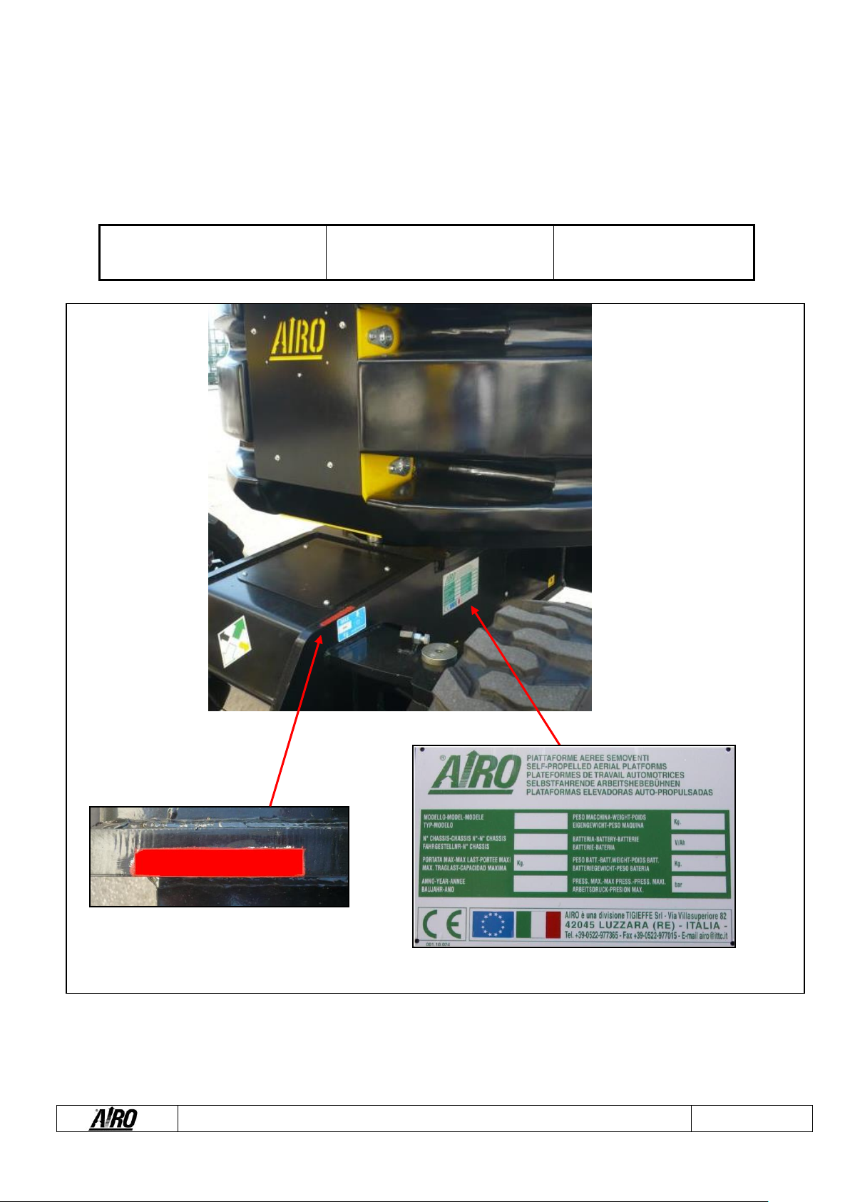
1.8. Identification.
When asking for technical service or spare parts, make sure to have the ID serial number of the machine. You will be asked about
it, so make a note of it and keep it with you. Should this plate (as well as the various stickers applied on the machine) be lost or
illegible, it is to be replaced as soon as possible. In order to identify a machine without a plate or a label, please check the
production number punched underneath the chassis. The exact location of the plate and the number punched on the chassis is
shown on the following label. Please check and copy them here below for your easier convenience in future.
MODEL: _________________
CHASSIS: __________________
YEAR: __________________
SG XXXXXX
Fig.1

User’s Manual – A12 JRTD A15 JRTD Series
Page 12
1.9. Location of main components.
The picture shows the machine and its own components:
1) Control panel
2) On-ground controls
3) Electric control unit
4) Hydraulic oil tank;
5) Diesel (fuel) tank
6) Diesel engine
7) Hydraulic pump to power travelling
8) Hydraulic pump to power the machine
operations
9) Hydraulic drive motors
10) Hydraulic motor for turret rotation;
11) (Optional) 230V outlet;
12) (Optional) Spirit level for the visual
control of the machine levelling;
13) Lifting cylinders
14) Starter battery
15) Power assisted steering
16) Inclinometer
17) Platform load limiter sensor (load cell);
18) Turntable.
Fig.2
1
2
3-4-5-
7-8-16
6-7-8
9
9
13
13
13
11-12
10-18
17
15
14
User’s Manual – A12 JRTD A15 JRTD Series
Page 13
2. TECHNICAL FEATURES OF THE STANDARD MACHINES.
THE TECHNICAL FEATURES OF THE PRODUCTS IN THE FOLLOWING PAGES CAN BE MODIFIED
WITHOUT PRIOR NOTICE
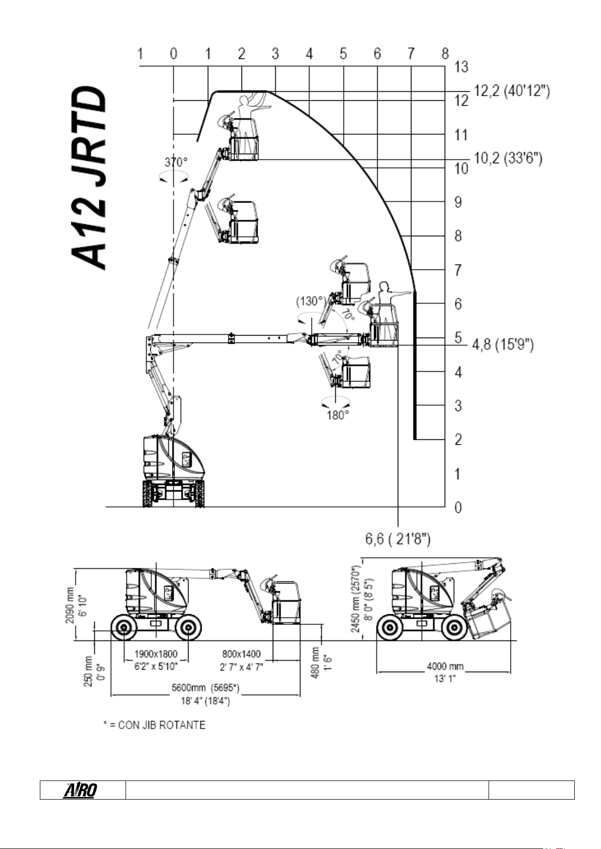
2.1. Model A12 JRTD.
A12 JRTD
Dimensions:
Maximum working height
12.2
m
40"
ft
Max. height of the platform floor
10.2
m
33 '5"
ft
Ground clearance
250
mm
9.8"
in
Max. outreach from turntable centre
7.1
m
23’3”
ft
Turret rotation (not continuous)
370
°
370
°
Platform rotation
180
°
180
°
Platform height for safety speed activation
< 3
m
<9’ 10”
ft
Internal steering radius
1.25
m
4 '1"
ft
External steering radius
3.6
m
11 '9"
ft
Maximum Capacity (m)
230
Kg
500
lbs
Max. number (n) of people on the platform –indoors
2
2
Mass weight of tool and material (me) (**) –outdoors
70
Kg
154.5
lbs
Max. number of people on the platform (n) –outdoors
2
2
Tool and material mass weight (me) (**) –outdoors
70
Kg
154.5
lbs
Maximum height during drive
Max
Max
Maximum platform dimensions (*****)
0.8 x 1.4
m
2' 7" x 4’
7"
ft
Maximum hydraulic pressure
380
Bar
5511
psi
Max. pressure of lifting circuit
250
Bar
3625.9
psi
Tire dimensions (****)
Ø 730 x 230
mm
Ø28.9"x
9.0"
in
Tire type (****)
10 x 16.5
10 x 16.5
Transport dimensions
5.6 x 1.8 x
2.09
m
18' 4" x 5’
9" x 6’ 10”
ft
Transport dimensions with retracted jib
4. x 1.8 x 2.45
m
13'1" x 5’
9" x 8’ 0"
ft
Machine weight w. no load (*)
5800
Kg
12786.12
lbs
Stability limits:
Longitudinal inclination
4
°
4
°
Lateral inclination
4
°
4
°
Maximum wind speed (***)
12.5
m/s
27.9
mph
Maximum manual load (***)
400
N
89.9
lbf
Max. load per wheel
2600
Kg
5700
lbs
Specifications:
Driving wheels
4
N
4
N
Max. drive speed
6
km/h
3.7
mph
Safety drive speed
0.6
km/h
0.4
mph
Oil tank capacity
90
l
23.7
gal
Maximum admissible gradient
38
%
38
%
Max. operating temperature
+50
°C
122
°F
Min. operating temperature
-15
°C
5
°F

User’s Manual – A12 JRTD A15 JRTD Series
Page 14
Diesel Power YANMAR “Stage III
Diesel engine type
3TNV-88
3TNV-88
Max. engine power
28.2
kW
37.8
hp
Rated Power
25
kW
33.5
hp
Starter battery
12 / 132
V/Ah
12 / 132
V/Ah
Total electrolyte quantity in the battery
7
l
1.8
gal
Diesel tank capacity
70
l
18.4
gal
Diesel Power YANMAR “Stage V / Tier 4 final”
Diesel engine type
3TNV-88
3TNV-88
Max. engine power
27.5
kW
37.4
hp
Rated Power
25
kW
33.5
hp
Starter battery
12 / 135
V/Ah
12 / 135
V/Ah
Total electrolyte quantity in the battery
7
l
1.8
gal
Diesel tank capacity
60
l
15.6
gal
380V three-phase electrical pump (optional)
Diesel engine power
NA
kW
NA
hp
Max. absorbed current
NA
A
NA
A
Max. drive speed
NA
km/h
NA
mph
230V single-phase electric pump (Optional)
Diesel engine power
NA
kW
NA
hp
Max. absorbed current
NA
A
NA
A
Max. drive speed
NA
km/h
NA
mph
(*) In certain cases, different limitations may be set. It is recommended to comply with the data shown on the machine plate.
(**) me = m –(n x 80).
(***) Wind speeds higher or equal to 12.5 m/s indicate that the machines can be also used outdoors; Wind speeds equal to 0 m/s indicate that the machines can
be used INDOORS ONLY.
(****) Standard off-road tires 10x116.5 filled with polyurethane foam.
(*****) Standard steel platform: 800x1400 mm (26x46 ft); Optional extra-large steel platform: 800x1800 mm (26x59 ft).
User’s Manual – A12 JRTD A15 JRTD Series
Page 15

User’s Manual – A12 JRTD A15 JRTD Series
Page 16
2.2. Model A15 JRTD.
A15 JRTD
Dimensions:
Maximum working height
15.1
m
49’6”
ft
Max. height of the platform floor
13.1
m
42’11”
ft
Ground clearance
250
mm
0’9”
in
Max. outreach from turntable centre
8.8
m
28 '9"
ft
Turret rotation (not continuous)
370
°
370
°
Platform rotation
180
°
180
°
Platform height for safety speed activation
< 3
m
<9’ 10”
ft
Internal steering radius
1.25
m
4 '1"
ft
External steering radius
3.6
m
11’9”
ft
Maximum Capacity (m)
230
Kg
500
lbs
Max. number (n) of people on the platform –indoors
2
2
Mass weight of tool and material (me) (**) –outdoors
70
Kg
154
lbs
Max. number of people on the platform (n) –outdoors
2
2
Tool and material mass weight (me) (**) –outdoors
70
Kg
154.5
lbs
Maximum height during drive
Max
Max
Maximum platform dimensions (*****)
0.8 x 1.4
m
2' 7" x 4’
7"
ft
Maximum hydraulic pressure
380
Bar
5511
psi
Max. pressure of lifting circuit
250
Bar
3626
psi
Tire dimensions (****)
Ø 730 x 230
mm
Ø28.7"
x9.0"
in
Tire type (****)
10 x 16,5
10 x 16,5
Transport dimensions
6,50 x 1,8 x
2,09
m
21' 3" x
5’ 10" x
6’ 10”
ft
Transport dimensions with retracted jib
4,70 x 1,8 x
2,40
m
15' 5" x
5’ 10" x
7’ 10”
ft
Machine weight w. no load (*)
6630
Kg
14617
lbs
Stability limits:
Longitudinal inclination
3.5
°
3.5
°
Lateral inclination
3.5
°
3.5
°
Maximum wind speed (***)
12.5
m/s
27.9
mph
Maximum manual load (***)
400
N
90
lbf
Max. load per wheel
3000
Kg
6600
lbs
Specifications:
Driving wheels
4
N
4
N
Max. drive speed
6
km/h
3.7
mph
Safety drive speed
0.6
km/h
0.4
mph
Oil tank capacity
90
l
24
gal
Maximum admissible gradient
35
%
35
%
Max. operating temperature
+50
°C
122
°F
Min. operating temperature
-15
°C
5
°F

User’s Manual – A12 JRTD A15 JRTD Series
Page 17
Diesel Power YANMAR “Stage III”
Diesel engine type
3TNV-88
3TNV-88
Diesel engine power
28
kW
38
hp
Starter battery
12 / 132
V/Ah
12 / 132
V/Ah
Total electrolyte quantity in the battery
7
l
2
gal
Diesel tank capacity
70
l
18
gal
Diesel Power YANMAR “Stage V / Tier 4 final”
Diesel engine type
3TNV-88
3TNV-88
Max. engine power
27.5
kW
37.4
hp
Rated Power
25
kW
33.5
hp
Starter battery
12 / 135
V/Ah
12 / 135
V/Ah
Total electrolyte quantity in the battery
7
l
1.8
gal
Diesel tank capacity
60
l
15.6
gal
380V three-phase electrical pump (optional)
Diesel engine power
NA
kW
NA
hp
Max. absorbed current
NA
A
NA
A
Max. drive speed
NA
km/h
NA
mph
230V single-phase electric pump (optional)
Diesel engine power
NA
kW
NA
hp
Max. absorbed current
NA
A
NA
A
Max. drive speed
NA
km/h
NA
mph
(*) In certain cases, different limitations may be set. It is recommended to comply with the data shown on the machine plate.
(**) me = m –(n x 80).
(***) Wind speeds higher or equal to 12.5 m/s indicate that the machines can be also used outdoors; Wind speeds equal to 0 m/s indicate that the machines can
be used INDOORS ONLY.
(****) Standard off-road tires 10x116.5 filled with polyurethane foam.
(*****) Standard steel platform: 800x1400 mm (26x46 ft); Optional extra-large steel platform: 800x1800 mm (26x59 ft).

User’s Manual – A12 JRTD A15 JRTD Series
Page 18

User’s Manual – A12 JRTD A15 JRTD Series
Page 19
2.3. Vibrations and noise.
Noise tests have been carried out under the most unfavourable conditions to study the effects on the operator. The level of acoustic
pressure weighed (A) at work places does not exceed 70dB(A) for each electric model.
For models with Diesel engine the level of acoustic pressure weighed (A) at work places does not exceed 106dB(A), the level of
acoustic pressure at ground control panel does not exceed 85dB(A), the level of acoustic pressure at platform control panel does
not exceed 78bD(A).
As to vibrations in ordinary working conditions:
▪The average weighted quadratic value in frequency of the acceleration which the upper members have to withstand is less
than 2.5 m/sec² for each of the models to which this manual refers.
▪The average weighted quadratic value in frequency of the acceleration which the upper members have to withstand is less
than 0.5 m/sec² for each of the models to which this manual refers.
User’s Manual – A12 JRTD A15 JRTD Series
Page 20
3. SAFETY SIGNS.
3.1. Personal protective equipment (PPE).
Always wear personal protective equipment according to current regulations concerning industrial health and safety (in particular,
hard hat and safety shoes are COMPULSORY).
It is the operator or safety manager’s responsibility to choose the personal protective equipment (PPE) depending on the activity to
be carried out. For their correct use and maintenance, refer to the equipment manuals themselves.
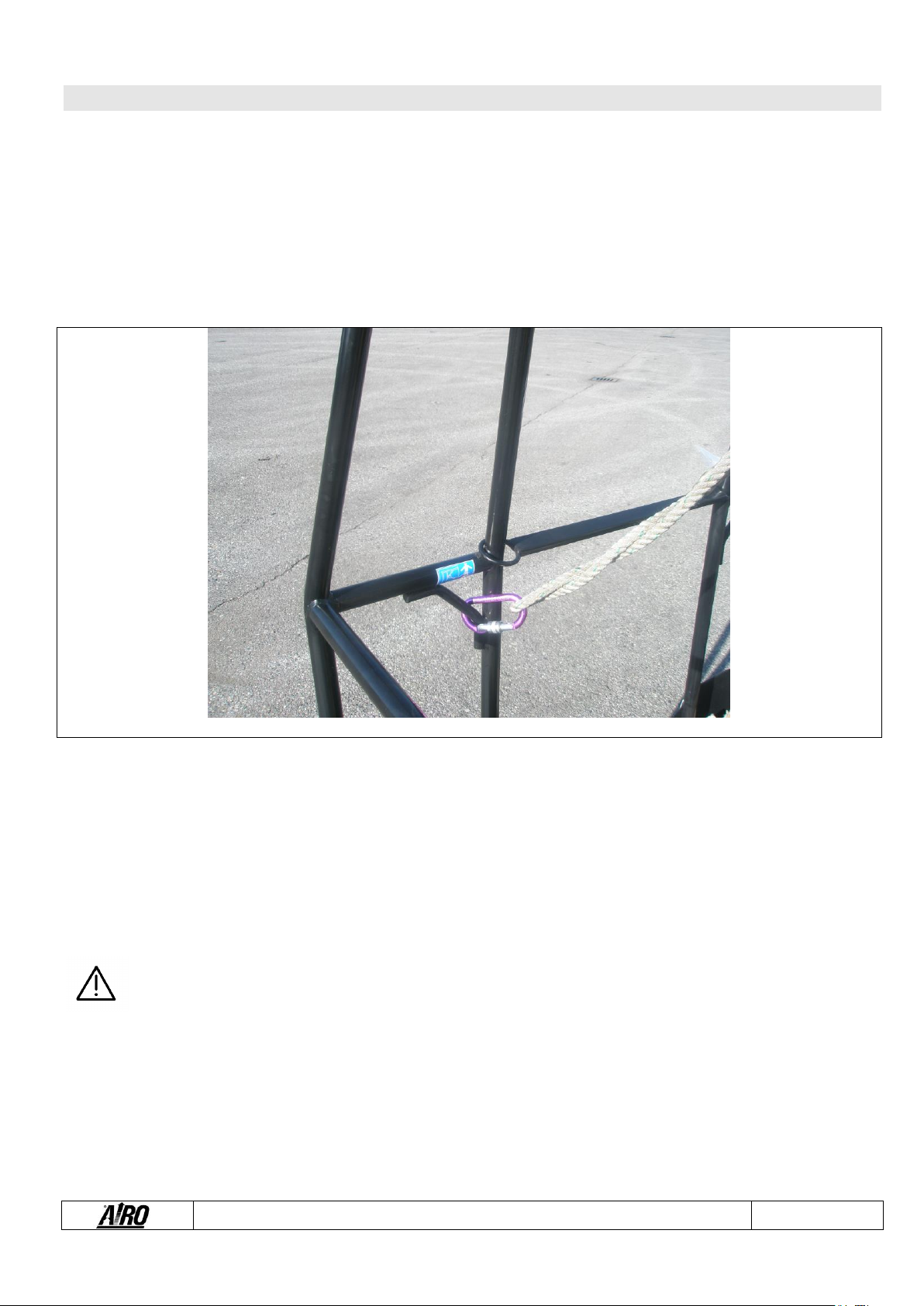
The use of safety harness is not compulsory except in certain countries with specific regulations. In Italy, the wearing of safety
harness is mandatory in accordance with the Sole Law on worker safety Dlgs 81/08.
The harness attaches to one of the anchors shown by the labels, as in the following picture.
Fig. 3
3.2. General safety norms.
▪Only adults (18 years old), after carefully reading this manual, are allowed to use the machine. The employer is
responsible for training.
▪The platform is designed to carry persons on board; therefore, compliance with the current local regulations
relevant to this class of machines (see paragraphs 1) must be ensured.
▪The machine is a two-men operation unit. This means at least one man must be on the ground and assigned
to all emergency operations as described in this handbook.
▪Always keep the machine at a safety distance from power lines as indicated in the next chapters.
▪Use the machine according to the capacity values indicated in the technical features section. The identification
plate shows the maximum number of people allowed on the platform, the maximum capacity and the mass
weight of tools and ancillary materials. Never exceed these figures.
▪Do NOT use the platform steelwork or any of its parts for grounding applications while welding on platform.
▪NEVER board/deboard passengers and NEVER load/unload any materials if the platform is not in the initial
boarding position.
▪The owner and/or safety manager are liable and responsible for due maintenance and repair operations to be
carried out strictly by skilled and qualified labours.
Other manuals for AIRO A Series
3
This manual suits for next models
2
Table of contents
Other TIGIEFFE Boom Lift manuals

Popular Boom Lift manuals by other brands


Skyjack
Skyjack SJ45 T+ Operation manual

JLG
JLG 100SX Operator's and safety manual

S.D.P.
S.D.P. EZ Hauler Series Preoperational Inspection and Maintenance

Haulotte
Haulotte STAR 6 Operator's manual

Terex
Terex Genie Z-60 DC Operator's manual

Oshkosh Corporation
Oshkosh Corporation JLG 600SC Operation and safety manual