Tigo EI User manual

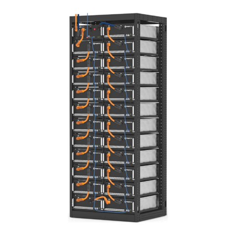
EI Battery (Including EI BMS)
!
1.1 Package Contents
1.2 System Configuration
BMS:
Index Item Quantity
1 BMS 1
2 BMS to Inverter Charging Cable (+) (2.0 m) 1
3 BMS to Inverter Charging Cable (-) (2.0 m) 1
4 BMS to Battery Module Power Cable (120 mm) 1
5 BMS Communication Cable (2.2 m) 1
6 COMM Communication Cable (200 mm) 1
7 Tightening Wrench 1
8 Wall Mounting Bracket 1
9 M5 Screw 4
10 Flat Washer 2
11 Grounding Wire (150 mm) 1
12 Lag Bolt 2
13 Wall anchor 2
14 Wire protector 2
15 Mounting Base 1
16 Safety manual 1
Battery Module:
Index Item Quantity
1 Battery Module 1
2 Battery Module Power Cable (690 mm) 1
3 COMM Communication Cable (600 mm) 1
4 M4 Screw 2
5 Grounding Wire (450 mm) 1
6 Quick Start Guide 1
Accessories:
Index Item Quantity
1 Battery Module Power Cable (1200 mm) 1
2 Battery Module COMM Communication Cable (1200 mm) 1
3 Grounding Wire (1200 mm) 1
4 Battery Base 1
5 Cover Plate 1
6 Wall Mounting Bracket 2
7 Wire Protector Ring 4
8 M4 Screw 8
9 Wall Bracket Accessories 1
10 Battery Module to BMS Power Cable (2500 mm) [optional] 1
1. General Information - Specications
ATTENTION - READ FIRST
!ATTENTION - Use the appropriate QSG's to perform the
physical installation of the EI system in the following order:
1. EI Battery
2. EI Inverter
3. EI Link
4. EI BMS
Quick Start Guide - EI BMS/TSB-3/EI Battery Accessories
Pg 1 of 3
1. This document is for general guidance only. Refer to the Energy Intelligence (EI) Inverter Installation & Operations Manual for more detail.
2. Before installing the system, verify that the package contents are intact and complete as per the packing list. Contact your dealer if there is equipment
damage or missing components.
PN: 002-00111-00 | REV 3.0 | Oct. 21, 2022
2. Installation
The EI Solution is ground mounted. All components stack together to form a complete unit. Extension batteries are installed to the right side of the main cabinet
as shown below.
1.2.1 Single Phase energy storage conguration examples:
2.1 Battery Base
1. Place the battery base 20 mm away from the wall.
2. Adjust the battery base levelers if needed. Verify using spirit level.
20 mm
levelers
2.2 Battery Module(s)
1. Load the battery modules on the base as per Section 1.2. 2. Secure the batteries on the left and right sides using the provided M4
Screws as shown.
1.2.2 Three phase energy storage system conguration examples:
200-250 mm 200-250 mm
200-250 mm 200-250 mm

EI Battery (Including EI BMS)
3. Electrical Connections
CAUTION - Check that all Disconnect switches are OFF before wiring. For personal safety always wear appropriate PPE.
!
Quick Start Guide - EI BMS/TSB-3/EI Battery Accessories
Pg 2 of 3
3.1 Battery Wiring
Open the BMS and all Battery wiring panels. Screws are located on the rear right side.
2.3 Battery Bracket
1. Secure battery bracket on top of Battery1.
2. Mark mounting holes on wall.
3. Remove mounting bracket from Battery1 and drill
out the holes.
4. Reinstall the battery bracket and secure to Battery1.
5. Secure mounting bracket to wall using appropriate
mounting hardware. Lag bolts and wall anchors
provided.
2.5 EI BMS Installation
1. Place the BMS on the top of Battery1.
2. Secure the BMS with M4 Screw on left and right side.
Note: This step is provided for reference.
Continue to the EI Inverter Quick Start
Guide to proceed with the rest of the
installation. Come back to this step once
the EI Inverter and EI Link have been
installed.
Battery1 is the battery that connects to the EI BMS.
2. Connect the BMS to EI Inverter Charging
Cables to the BAT+ and BAT- ports on the
BMS.
3. Connect the other end of the BMS to EI
Inverter Charging Cables to the
corresponding BAT+ and BAT- ports in
the EI Inverter.
4. Connect one end of the BMS
Communication Cable (RJ45 ends) to the
BMS port and the other end to the EI
Inverter BMS port.
5. Connect BMS and EI Link grounding
terminals with a properly sized (installer
made) grounding cable.
6. Tighten the BAT+, BAT-, and
communication cable connectors using
the provided tightening wrench.
7. Place the wire protector ring around the
BAT+. BAT-, and COM cables and then
snap the ring into the BMS upper
knockout.
2.4 Extension batteries (if applicable)
1. Follow the same procedure as above to install the
battery base and the wall mount bracket.
2. Install the two smaller cover brackets on top of the
battery module.
3. Press down and secure the top cover onto the
battery.
Note: Ensure all prior steps are completed before making electrical connections.
Note: Crimp the male connector to the red (+) cable. Crimp the female connector to the black (-) cable.
1. Strip 15mm of insulation off the Charging Cables and crimp the connectors from inverter accessories package onto the ends.
3.1.1 BMS to Inverter
BMS
BMS
BMS
to
EI Link
PN: 002-00111-00 | REV 3.0 | Oct. 21, 2022

EI Battery (Including EI BMS)
Quick Start Guide - EI BMS/TSB-3/EI Battery Accessories
Pg 3 of 3
Note: Previous step’s wiring not shown
1. BMS to Battery1 connections:
• Battery Module Power Cable from BMS B+ to Battery1 B+.
• Comm Communication Cable from BMS COMM to Battery 1 COMM1.
• Grounding Wire from BMS Ground to Battery1 Ground.
2. BMS to Battery2 connections:
• Battery Module Power Cable from BMS B- to Battery2 B-
3. Battery1 to Battery2 connections:
• Battery Module Power Cable from Battery1 B- to Battery2 B+.
• Comm Communication Cable from Battery1 COMM2 to Battery2 COMM1.
• Grounding Wire from Battery1 Ground to Battery2 Ground.
3.1.3. Battery Connections (Two Batteries)
Connect the following ports between the BMS, EI Inverter, and Battery1:
1. Connect Battery Module Power Cable from BMS B+ to Inverter B+ port.
2. Connect Battery Module Power Cable from BMS B- to Inverter B- port.
3. Connect Battery COMM cable from BMS COMM to Battery1 COM1 port.
4. Connect BMS Ground wire from BMS ground screw to Battery1 ground screw.
3.1.2 Battery Connection (One Battery)
1. BMS to Battery1: B+ to B+; COMM to COMM1;
Ground to Ground
2. BMS to Battery3: B- to B-
3. Battery1 to Battery2: B- to B+; COMM2 to COMM1;
Ground to Ground
4. Battery2 to Battery3: B- to B+; COMM2 to COMM1;
Ground to Ground
3.1.4 Three Batteries
1. BMS to Battery1: B+ to B+; COMM to COMM1;
Ground to Ground.
2. BMS to Battery3: B- to B-.
3. Battery1 to Battery2: B- to B+; COMM2 to COMM1;
Ground to Ground.
4. Battery2 to Battery3: B- to B+; COMM2 to COMM1;
Ground to Ground.
5. Battery3 to Battery4: B- to B+; COMM2 to COMM1;
Ground to Ground.
3.1.5 Four Batteries
4. Your Customer Service Contact
Tigo Energy Italy
Srl Via Calamandrei 36 52025
Montevarchi Tuscany, Italy
Americas: +1 408 402 0802
International: 00800 2255 8446
https://support.tigoenergy.com/
BMS
Battery1
Battery2
BMS
B+
B-
COM1
COM2
B-
B+
BAT +
BAT-
BMS
COMM
B+
B-
COM1
COM2
BMS
Battery1
BAT+
BAT-
BMS
Inverter Ports:
Battery3
B+
B-
COM1
COM2
Battery2
B+
B-
COM1
COM2
B-
B+
BAT +
BAT-
BMS
COMM
B+
B-
COM1
COM2
BMS
Battery1
BAT+
BAT-
BMS
Inverter Ports:
Battery3
B+
B-
COM1
COM2
Battery2
B+
B-
COM1
COM2
Battery4
Battery1 Battery2
Battery3
Battery1 Battery2
Battery3
Battery4
PN: 002-00111-00 | REV 3.0 | Oct. 21, 2022
Other manuals for EI
3
This manual suits for next models
2
Popular Camera Accessories manuals by other brands

Sony
Sony Electronic Viewfinder HDVF-C30W Maintenance manual
C&D Technologies
C&D Technologies TEL Series Installation and Operating Procedures

E-Image
E-Image EL-1250S user manual

Moog Videolarm
Moog Videolarm POD7CW Installation instructions manual
LEAB
LEAB 012-00022GF user manual
Philips
Philips LongLife 6F22L1F brochure


