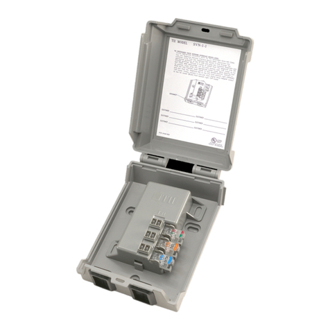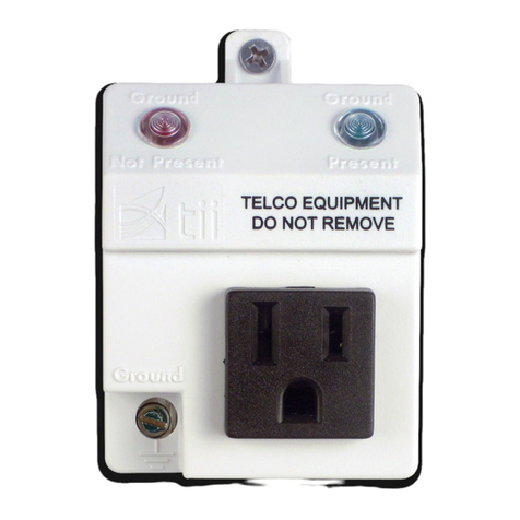
TII P/N 92202401
141 Rodeo Drive TII 821
Edgewood, NY 11717 Selective Ringing Module
Customer Service/Sales 888-844-4720 02/08 Rev B
INSTALLATION NOTE
GENERAL
This installation note covers the installation and field
testing of the TII 821 Selective Ringing Module. The
unit is self contained and requires no external power.
One unit serves all telephones at a station.
This unit contains electronic components and is
designed to be used in conjunction with a station
protector capable of limiting surge voltages to 1000
volts. A gas tube station protector is recommended.
WARRANTY RETURNS
Units are completely encapsulated and are not
repairable. See TII warranty. If unit fails within
warranty period, request a return authorization from
the factory. Return the unit prepaid. Units which fail
through normal wear and tear after warranty period
should be discarded.
DESCRIPTION
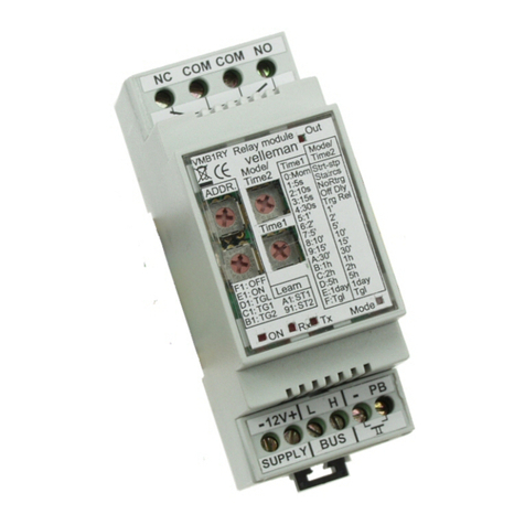
The TII 821 Selective Ringing Module is a hermetically
sealed electronic module used to isolate the ringing
circuit of a partyline station from all ringing signals
except the proper one for that particular station. This
allows the use of any combination of both selective,
grounded ringers and non-selective, bridged ringers at
that one station. The use of the TII 821 eliminates the
need for a Ringer Isolator.
One unit mounted at the station protector serves all
telephones at that station. Selective ringing for
various ringing schemes is provided by wiring the
module according to the instructions given below. The
TII 821 is compatible with the following ringing
schemes:
Two-party
Four-party superimposed, full selective
Four or eight partysemi-selective
INSTALLATION
Installation of the 821 SRM
If the red wire is not already connected to a
previous electronic module, connect it to the ring
post of the station protector.
If the green wire is not already connected to a
previous electronic module, connect it to the tip
post of the station protector.
Connect the blue wire to the red wire of the
customer bridge.
Connect the white wire to the green wire of the
customer bridge.
The yellow and black wires should be connected
as follows according to the party it is being used
on.
PARTY 1 (-RING)
Connect the black wire to the red wire of the 821.
Connect the yellow wire to the ground post of the
station protector.
PARTY 2 (-TIP)
Connect the black wire to the green wire of the 821.
Connect the yellow wire to the ground post of the
station protector.
PARTY 3 (+RING)
Connect the black wire to the ground post of the
station protector. Connect the yellow wire to the red
wire of the 821.
PARTY 4 (+TIP)
Connect the black wire to the ground post of the
station protector. Connect the yellow wire to the green
wire of the 821.
NOTE: The station sets may be wired either for
grounded ringing or for bridged ringing. By assuring
that all of the station sets are wired for bridged ringing
(1FR), it is only necessary to terminate the Tip and
Ring of the station wire. However, if any set(s) at this
station is wired for grounded ringing, the ringer return
lead of the station wire (usually yellow) must be tied to
the blue wire of the respective 821 if the customer is a
Tip party, or the white wire if the customer is a Ring
party. This will convert the station to bridged ringing
without modifying the sets. However, any set with
identification ground must be rewired to remove the
resistance to ground.
