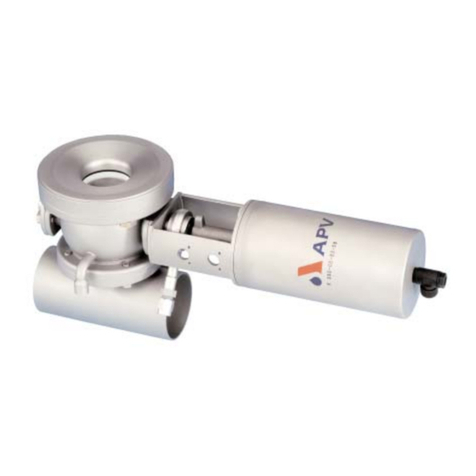
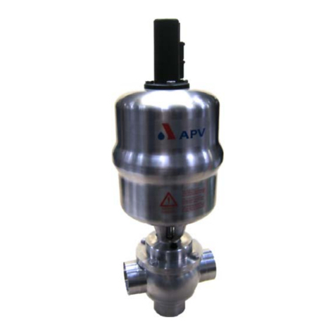
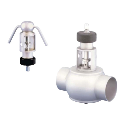
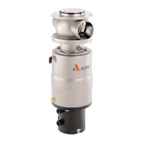
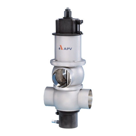
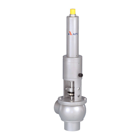
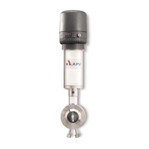
SPX APV DELTA SVS1F DN 125 User manual

Read and understand this manual prior to
operating or servicing this product.
Operating Manual
DELTA SVS1F DN 125-250
Butterfly Valve


1. General Terms 2
2. Safety Instructions 2
3. Mode of Operation 3
4. Auxiliary Equipment 4
5. Installation 5
5.1. Welding Instructions 5
6. Dimensions / Weights 6
7. Technical Data 7
8. Materials 7
9. Maintenance 8
10. Service Instructions 9 - 11
11. Trouble Shooting 12
12. Spare Parts Lists
SVS1F - A DN 125 - 250 - RN 01.038.020
SVS1F - M DN 125 - 250 - RN 01.038.021
manual actuation with locking device
SVS1F - DN 125 - 250 - RN 01.038.10
manual actuation with locking device
for valve feedback
SVS1F - DN 125 - 250 - RN 01.038.10 - 1
Table of Content Page
1
Butterfly Valve
DELTA SVS1F DN125-250
Operating Manual rev.2
UK


This operating manual has to be read and observed by the
responsible operating and maintenance personnel.
We have to point out that we will not accept any liability for
any damage or malfunctions resulting from the non-compliance
with this operating manual.
Descriptions and data given herein are subject to technical changes.
2. Safety Instructions
DANGER!
- Before any maintenance of the valve, depressurize the line system
and discharge it if possible.
- Do not reach into the open valve or into the yoke!
Risk of bruising by movable parts.
- Valve in dismantled state: risk of injury by sudden
valve actuation!
- Observe the following service instructions to ensure safe
maintenance of the valve.
- The welded housing of the actuator is under spring load -
do not attempt to open it by force!
1. General Terms
2
UK
Butterfly Valve
DELTA SVS1F DN125-250
Operating Manual rev.2

3. Mode of Operation
3
UK
Butterfly Valve
DELTA SVS1F DN125-250
Operating Manual rev.2
Use of high-quality stainless steel and seal material to the specified
requirements, the butterfly valve range DELTA SVS1F is applicable
in the food and beverage industries as well as in the chemical and
pharmaceutical industries.
The function of the butterfly valve is to shut off line sections.
Valves of the series DELTA SVS1F can either be operated manually
or remote controlled via a pneumatic actuator. Manual operation
and pneumatic actuator including add-on pieces are inter-
changeable.
Actuation by pneumatic actuator.
Reset by spring force into the limit position closed.
Extension of operating time of actuated valves by pneumatic air
throttle or adjusting screw in the control unit CU3 to optimize the
flow behaviour.
The butterfly valve can also be used in vacuum systems.
The valve opens and closes by turning the disc by 90°. Manual
actuation provides for locking of the disc in partly open position.
Smooth valve passage without diversion of line flow.
The opening diameter complies with the size of the inner line
diameter.
Cleaning of the product wetted valve surface is performed during
cleaning of the pipeline.
4. Auxiliary Equipment
Valve position indication - valve with pneumatic actuator:
Proximity switches to signal the limit position of the valve disc
can be installed in the yoke area if required.
We recommend to use our APV standard proximity switches.
Type: three-wire proximity switch (ref.-No. 08-60-011/93)
Operating distance: 4mm / diameter: 11mm / length: 30 mm.
Feedback complete with support and proximity switch
(ref.-No. 15-33-023/93) for a limit position.
Using a valve position indicator other than APV, we cannot accept
any liability for faulty function.

4
4. Auxiliary Equipment
- An adapter is required to install the control unit on the SVS1F valve.
UK
Butterfly Valve
DELTA SVS1F DN125-250
Operating Manual rev.2
- To install the control unit on a butterfly valve a special pneumatic
actuator is needed. The standard actuator must be replaced.
designation ID :
CU 31 Direct Connect L 804 629
CU 21 Profibus L 804 437
CU 31 Device Net L 804 611
CU 31 AS - Interface L 804 701
designation ID :
CU 2 adapter SVS1F / DKR2 L 801 195
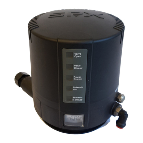
CU3 control unit
with adapter
actuator for control unit
DN 125 - 150 ref.-No.: 000 - 15 - 37 - 106/17
DN 200 - 250 ref.-No.: 000 - 15 - 37 - 103/17
Valve position indication - valve with manual actuation:
Specific manual actuations with feedback feature are available:
Feedback of both disc positions
open and closed are possible.
CONTROL UNIT
Units with feedback switch and solenoid valve for the pneumatic
control of the valve for assembly on the actuator are also available
in fieldbus technology.
The assembly of a CU3 control unit on a pneumatic actuator
is possible.
The following different designs are available:

5
5. Installation
UK
In normal installation position, the actuator is vertically to the top.
Depending on the requirements of the respective application, the
installation position is optional.
Valve installation can be undertaken between FG 1 flanges and
flanges according to DIN.
Attention : Observe welding instructions!
5.1 Welding Instructions
- Welding shall only be carried out by certified welders (EN 287 - 1).
(seam quality EN 25817 ,,B”).
- The welding of the mating flanges must be undertaken in such a way
that deformation strain cannot arise.
- TIG orbital welding is the most appropriate method!
- Before welding, all sensitive parts must be removed!
Dismantle the valve core with seals, etc. from the mating flanges.
- After welding of the mating flanges and after work at the pipelines,
the corresponding parts of the installation and pipelines must be
cleaned from welding residues and soiling.
If these cleaning instructions are not observed, welding residues
and dirt particles can settle in the valve and cause damage or be
carried over to other parts of the installation.
- Any damage resulting from the non-observance of these welding
instructions is not subject to our guarantee.
Butterfly Valve
DELTA SVS1F DN125-250
Operating Manual rev.2

6
6. Dimensions / Weights
UK
dimensions in mm
DN A A1 B C D E F G H
125 491 625 97 54 125 108 130 181 280
150 505 640 110 54 150 108 130 194 280
200 573 705 138 65 200 107 180 222 310
250 602 734 166 65 250 107 180 250 310
E
H
G
F
D
B
B
A
A1
C
D
weights in kg
with with
DN manual operation actuator
125 12,9 20,9
150 15,6 23,6
200 24,6 39,6
250 38,2 53,2
Butterfly Valve
DELTA SVS1F DN125-250
Operating Manual rev.2

7
UK
7. Technical Data
8. Materials
- valve disc 1.4404 / 1.4571
- housing flange / mating flange 1.4404
- SV seal, flange seal
standard: EPDM
option: HNBR, VMQ, FPM
- bearings Polyamide
- handle 1.4301
actuator
- yoke, actuator, bracket 1.4301
- coupling 1.4057
- indicator PE - solid
- spindle bearing Polyamide PA 12 / POM
- piston Polyacetal POM
- air connection Polyamide PA 6.6
- max. line pressure 10 bar
- max. operating temperature 135o C EPDM, HNBR,
*VMQ, *FPM
- short-term load 140o C EPDM,HNBR,
*VMQ, *FPM
*(no steam)
- vacuum tightness 2 mbar
- opening angle butterfly valve 90o C
min. air pressure for actuator 6 bar
max. air pressure for actuator 10 bar
- pneumatic air connection (for hose) 6 x 1
(use dry and clean pneumatic air, only)
DELTA SVS1F DN 125 150 200 250
pneumatic actuator 125 125 180 180
required turning torque MD Nm 30 45 65 80
pneum. air consumption at 6bar V NI 5,5 5,5 11 11
kvs values in m3/h 850 1500 2500 4000
Butterfly Valve
DELTA SVS1F DN125-250
Operating Manual rev.2

8
UK
- The maintenance intervals depend on the application of the valve
and should be determined by the operator carrying out regular
checks of the valve.
- There are a few wear parts on SVS1F butterfly valves, principally
the SV seal, flange seals and bearings.
- It is recommended that spare seals and bearings are
kept by the user. Complete seal kits for the valve service
are available (see spare parts lists).
- If damaged seals are replaced, generally all seals and
bearings should be changed.
- Dismantling and installation of seals according to service
instructions.
- All seals must be slightly greased before their installation.
Grease SV seal according to (fig.1)
- especially the cross bores.
- Assembly of valve and change of valve design NC or NO
see service instructions.
- Installation of actuator see service instructions.
- The inner parts of the actuator are maintenance free.
-Attention! Use food-grade special grease being suited for the
respective seal material, only.
Recommendation:
APV-food-grade grease for EPDM, FPM, HNBR and NBR
(0,75 kg /can - ref. No. 000 70-01-019/93)
(60 g /tube - ref. No. 000 70-01-018/93)
or
APV-food-grade grease for VMQ
(0,6 kg /can - ref. No. 000 70-01-017/93)
(60 g /tube - ref. No. 000 70-01-016/93)
!!! Do not use grease containing mineral oil for EPDM seals !!!
!!! Do not use Silicone-based grease for VMQ seals !!!
grease
grease
grease
SV seal
9. Maintenance
Butterfly Valve
DELTA SVS1F DN125-250
Operating Manual rev.2

9
UK
10.1 Dismantling from the line system
a. Shut off the line pressure and drain pipeline if possible.
b. Disconnect the pneumatic air line at the turning actuator.
c. Release clamp connection at support of proximity switches.
Pull off proximity switch.
d. Remove flange screws (8).
e. Take butterfly valve out of the flanges.
ATTENTION! Dismantling from the line system
with closed valve, only.
10.2 Dismantling of the actuating device
-Valve design with actuator:
(spare parts list RN 01.038.020)
Remove fastening screws (10) at the yoke (12).
Lift turning actuator (14) with yoke and coupling (11)
off to the top.
Attention! With installed valve position indicators,
see to the position of the operating cam.
-Manual valve design with locking device:
(spare parts list RN 01.038.10)
or
manual valve design with locking device
for valve feedback:
(spare parts list RN 01.038.10-1)
Remove fastening screw (2).
Detach thrust ring (3), handle (4) and scale (1)
to the top.
10. Service Instructions
Butterfly Valve
DELTA SVS1F DN125-250
Operating Manual rev.2

10
UK
10. Service Instructions
10.3 Dismantling of inner parts
seal ring, bush bearings, valve disc
-Remove all fastening screws (9) around the valve housing and
part the housing halves.
10.4 Replacement of seals
a. Take the flange seals (4) out of the groove and replace them.
Remove the fastening screws (9) of the valve core and part
the housing halves.
b. Turn the valve disc (2) in the sealing ring into open position.
c. Take the bush bearings (5) from the disc bolts.
d. By slight pressing, the seal ring (6) is deformed longitudinally.
Slide the seal ring over the short disc bolt and over the long
disc bolt off the disc.
e. Clean the valve disc (2).
10.5 Installation of seals and bush bearings
ATTENTION! Reminder to use the suitable grease
for the respective seal material.
a. Provide the inner surfaces of the cross bores as well as the
disc bolts with a thin layer of grease before the installation of the
disc.
b. Slide the sealing ring (6) over the long disc bolt, at first, and then over
the short disc bolt on the disc (2).
c. Push the bush bearing (5) on the disc bolts.
d. Turn the valve disc in the seal ring into open position.
e. Place the valve disc with seal ring and bush bearings into one
housing half. Adjust the other housing half and tighten it crosswise
with the inner hexagon screws (9).
ATTENTION! Tightening the inner hexagon screws,
the valve disc must be in open position.
f. Fasten the mating flanges (3) with the screws (8).
Butterfly Valve
DELTA SVS1F DN125-250
Operating Manual rev.2

10.6 Installation of the actuating device
-Proceed in reverse order to the steps described in 10.2.
- With the manually operated butterfly valve, the valve disc and
the handle are in a line.
- For the assembly of the actuator, see to the requested
valve design NC or NO.
NC = normally closed
Valve disc is closed.
Place the pneumatic actuator with yoke and coupling on the valve
and tighten them with the screws (10).
The upper operating cam must be adjusted to the upper yoke bore.
NO = normally open
Valve disc is open.
Place the pneumatic actuator with yoke and coupling on the valve
and tighten them with the screws (10).
The lower operating cam must be adjusted to the lower yoke bore.
DANGER! After the assembly of the actuator, do not
touch the open valve! Risk of bruising by
movable valve parts! Risk of injury through
sudden valve operation!
10.7 Installation of feedback units
- Valve feedback OPEN:
Installation of the valve feedback in the lower yoke bore.
- Valve feedback CLOSED:
Installation of the valve feedback in the upper yoke bore.
- Plug proximity switch holder into the yoke and fasten it.
Introduce proximity switch into the holder until it stops and
fasten it with the clamp screw.
10. Service Instructions
UK
Butterfly Valve
DELTA SVS1F DN125-250
Operating Manual rev.2
11

12. Spare Parts
(see annex)
11. Trouble Shooting
UK
Butterfly Valve
DELTA SVS1F DN125-250
Operating Manual rev.2
Trouble Remedy
Valve is untight Replace seal ring (6),
check line pressure.
Housing in the flange area is untight Replace flange seal (4).
Spindle passage at housing is untight Replace seal ring (6) and
bush bearings (5).
Air escapes from the air connection Fasten or replace air connection
at the pneumatic actuator.
Actuator does not work,
air escapes permanently from
the vent bore Replace pneumatic actuator.
12

Your local contact:
APV
Zechenstraße 49
D-59425 Unna
Phone: +49(0) 23 03/ 108-0 Fax: +49(0) 23 03 / 108-210
For more information about our worldwide locations, approvals, certifications, and local representatives, please visit www.apv.com.
Copyright © 2008 SPX Corporation
he information contained in this document, including any specifications and other product details, are subject to change without notice.
While we have taken care to ensure the information is accurate at the time of going to press, we assume no responsibility for errors or
omissions nor for any damages resulting from the use of the information contained herein.
UK
ranslation of original manual
BA SVSF 125002
ID-No.: H 2 0 1 5 7 0
rev. 2


This manual suits for next models
2
Table of contents
Other SPX Control Unit manuals
SPX
SPX APV DELTA DE3 User manual

SPX
SPX Waukesha Cherry-Burrell W Series User manual

SPX
SPX APV CU4 User manual

SPX
SPX DSV User manual

SPX
SPX 9500 Product guide

SPX
SPX APV DELTA UF3 User manual

SPX
SPX DELTA SW4 User manual

SPX
SPX W Series User manual

SPX
SPX APV DELTA SV1B User manual

SPX
SPX APV DELTA MS4 User manual

SPX
SPX APV DELTA PR2 User manual

SPX
SPX APV DELTA DF plus 2 User manual
SPX
SPX APV DELTA SWmini4 User manual

SPX
SPX APV DELTA MF4 User manual

SPX
SPX APV DELTA SDU4 User manual

SPX
SPX Waukesha Cherry-Burrell W-Series User manual

SPX
SPX APV DELTA DET3 User manual

SPX
SPX APV DELTA M4 User manual

SPX
SPX APV DELTA DKRT2 User manual