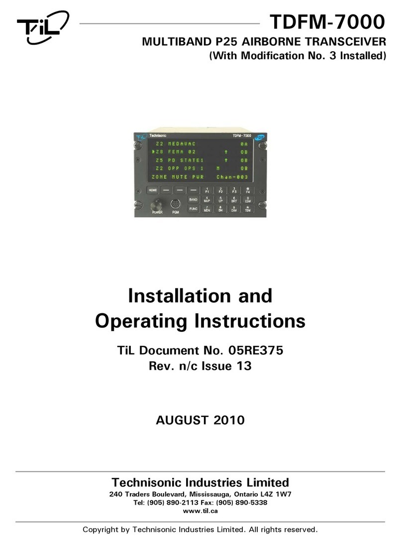
TIL TDFM-136 Manual

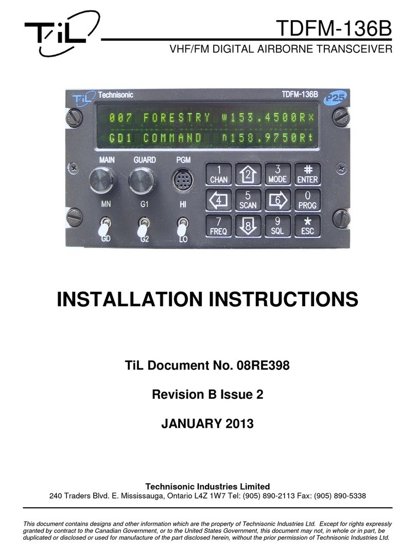
TDFM-136
VHF/FM DIGITAL AIRBORNE TRANSCEIVER
INSTALLATION & OPERATING
INSTRUCTIONS
Til Document No.
99RE255
Rev. D
Issue 2
(Software R1V40)
OCT 2000
Technisonic Industries Limited
250 Watline Avenue, Mississauga, Ontario L4Z 1P4 Tel: (905) 890-2113 Fax: (905) 890-5338
3840 E. Robinson road, Suite 214, Amherst, New York 14228 Tel: (716) 691-0669
This document contains designs and other information which are the property of Technisonic Industries Ltd. Except for rights expressly
granted by contract to the Canadian Government, or to the United States Government, this document may not, in whole or in part, be
duplicated or disclosed or used for manufacture of the part disclosed herein, without the prior permission of Technisonic Industries Ltd.

99RE255 TDFM-136 Installation & Operating Instructions
ii
! CAUTION STATIC SENSITIVE !
This unit contains static sensitive devices. Wear a grounded wrist strap and/or conductive gloves when
handling printed circuit boards.
FCC COMPLIANCE
This device complies with Part 15 of the FCC Rules. Operation is subject to the following two
conditions: (1) this device may not cause harmful interference and (2) this device must accept
any interference received, including interference that may cause undesired operation.
NOTE: This equipment has been tested and found to comply with the limits for a Class B digital
device, pursuant to Part 15 of the FCC Rules. These limits are designed to provide reasonable
protection against harmful interference in a residential installation. This equipment generates,
uses, and can radiate radio frequency energy and, if not installed and used in accordance with
the instruction manual, may cause harmful interference to radio communications. However, there
is no guarantee that interference will not occur in a particular installation. If this equipment does
cause harmful interference to radio or television reception, which can be determined by turning
the equipment off and on, the user is encouraged to try to correct the interference by one or more
of the following measures:
•Re-orient or relocate the receiving antenna
•Increase the separation between the equipment and receiver
•Connect the equipment into an outlet or circuit different from that to which the receiver is
connected.
•Consult the dealer or an experienced radio/TV technician for help.
WARRANTY INFORMATION
The Model TDFM-136, VHF/FM Digital Transceiver is under warranty for one year from date of purchase.
Failed units caused by defective parts, or workmanship should be returned to:
Technisonic Industries Limited Technisonic Industries Limited
250 Watline Avenue 3840 E. Robinson Road, Suite 214
Mississauga, Amherst,
Ontario L4Z 1P4 New York 14228
Tel: (905) 890-2113 Tel: (716) 691-0669
Fax: (905) 890-5338

TDFM-136 Installation & Operating Instructions 99RE255
iii
bmaskclr>pctgqgml>r_`jcX>Öéë>WWpcPSS
bmaskclr>pctgqgml>r_`jcX>Öéë>WWpcPSSbmaskclr>pctgqgml>r_`jcX>Öéë>WWpcPSS
bmaskclr>pctgqgml>r_`jcX>Öéë>WWpcPSS
pctLM
pctLMpctLM
pctLM
>àííîÑ
>àííîÑ>àííîÑ
>àííîÑ n_ec
n_ecn_ec
n_ec bcqapgnrgml
bcqapgnrgmlbcqapgnrgml
bcqapgnrgml b_rc
b_rcb_rc
b_rc _nnpL
_nnpL_nnpL
_nnpL
A Section 2
(all pages)
Change Section 2 to reflect operating
instructions for R0V20 software.
MARCH
2000
R.R.
B Section 2
(all pages)
page 3-8
Change Section 2 to reflect operating
instructions for R0V44 software.
Change figure 3-4 to reflect new jumper
locations.
JUNE
2000
R.R.
C Section 2
(all pages)
Change Section 2 to reflect operating
instructions for R1V00 software.
SEPTEMBER
2000
R.R.
D
Issue 1
Section 2
(all pages)
3-7, 3-8
Expand descriptions of commands
Update Fig 3-4 & 3-5
OCTOBER
2000
A.M.
D
Issue 2
Section 2
all pages
Section 3
pg. 3-7, 3-8
Added ‘Set Command Permissions’, L4-1.
Moved: Upload, Download, Sidetone adjust
commands from L4-2, -8, -7 to L3-2, -8, -7
Moved: Edit Noise Squelch L4-9 to L2-9
Fixed typo’s , added information for clarity
MAY
2001
A.M.

99RE255 TDFM-136 Installation & Operating Instructions
iv
Table of Contents
Section 1 – General Description ____________________________________________1-1
1.1 Introduction..................................................................................................1-1
1.2 Description...................................................................................................1-1
1.3 Purpose of Equipment.................................................................................1-1
1.4 Model Variation............................................................................................1-2
1.5 Technical Characteristics ............................................................................1-2
1.6 Certification Summary .................................................................................1-4
Section 2 – Operating Instructions__________________________________________2-1
2.1 Command Levels ........................................................................................2-1
2.2 Command Types .........................................................................................2-2
2.3 Edit Status Indicators...................................................................................2-2
2.4 Programming Commands – Overview ........................................................2-3
2.5 Operator Level 1 Commands ......................................................................2-4
L1-1 Select the Operating Memory for the Main Channel ...........................2-4
L1-2 Increase Display Brightness................................................................2-4
L1-3 Edit Channel Operating Mode .............................................................2-4
L1-4 Scroll Backwards through Available Memories ...................................2-5
L1-5 Select Scan List and Start/Stop Scan .................................................2-5
L1-6 Scroll Forward through Available Memories........................................2-5
L1-7 Edit Channel Operating Frequency .....................................................2-5
L1-8 Decrease Display Brightness ..............................................................2-6
L1-9 Edit Channel Squelch Modes ..............................................................2-6
Select CTCSS Tones or DCS Codes .............................................2-7
Select P25 TalkGroup ....................................................................2-7
L1-0 Command Level Up ............................................................................2-8
L1-# Save Pending Changes.......................................................................2-8
L1-* Abandon Pending Changes .................................................................2-8
2.6 Operator Level 2 Commands ......................................................................2-9
L2-1 Program Channel Information .............................................................2-9
L2-2 Copy Guard to Main ............................................................................2-10
L2-3 Lock Keypad........................................................................................2-10
L2-4 Edit Network Access Code..................................................................2-10
L2-5 Edit Scan List Membership..................................................................2-10
L2-6 Edit Channel Description.....................................................................2-11
L2-8 Copy Main to Guard ............................................................................2-11
L2-9 Edit Noise Squelch ..............................................................................2-12
L2-0 Command Level Up ............................................................................2-12
L2-* Command Level Down.........................................................................2-12
Unused Level 2 Command Keys .................................................................2-12
2.7 Operator Level 3 Commands ......................................................................2-13
L3-1 Select Boot Channel............................................................................2-13
L3-2 Data Upload ........................................................................................2-13
L3-4 Display Release and Version Information ...........................................2-13
L3-6 Configure PTT Timer...........................................................................2-13

TDFM-136 Installation & Operating Instructions 99RE255
v
L3-7 Select Guard or Sidetone Audio Adjust...............................................2-13
L3-8 Data Download....................................................................................2-14
L3-9 Display Channel Squelch Parameters.................................................2-14
L3-0 Command Level Up ............................................................................2-14
L3-* Command Level Down.........................................................................2-14
Unused Level 3 Command Keys .................................................................2-14
2.8 Maintenance Commands - Level 4..............................................................2-15
Set Command Permissions ........................................................................2-15
Command Level Down ................................................................................2-16
Unused Level 4 Command Keys .................................................................2-16
Section 3 – Installation Instructions ________________________________________3-1
3.1 General........................................................................................................3-1
3.2 Equipment Packing Log...............................................................................3-1
3.3 Transceiver Installation................................................................................3-1
3.4 Installation Kit - Contents.............................................................................3-1
3.5 Antenna Installation .....................................................................................3-1
3.6 Installation – Connector Pin-out ..................................................................3-2
3.7 Wiring Instructions.......................................................................................3-4
3.8 Transmitter Side Tone Level Adjustment ....................................................3-6
3.9 Main and Guard Noise Squelch Adjustment ...............................................3-6
3.10 Reference Layouts ......................................................................................3-7
Table of Tables
Section 1 – General Description ____________________________________________1-1
Table 1-1. TDFM-136 General Characteristics................................................1-2
Table 1-2. TDFM-136 Operational Characteristics..........................................1-3
Table 1-3. TDFM-136 Receiver Characteristics ..............................................1-3
Table 1-4. TDFM-136 Transmitter Characteristics ..........................................1-4
Table 1-5. TDFM-136 Environmental Testing Summary.................................1-4
Section 2 – Operating Instructions__________________________________________2-1
Table 2-1. Command Level Table ...................................................................2-1
Table 2-2. Command Matrix ............................................................................2-3
Table 2-3. Operating Modes ............................................................................2-4
Table 2-4. Receive and Transmit Squelch Modes...........................................2-7
Table 2-5. Command Level Table ...................................................................2-7
Table 2-5. Command Level Table ...................................................................2-7
Table 3-1 Rear Connector Pin Assignments ..................................................3-2

99RE255 TDFM-136 Installation & Operating Instructions
vi
Table of Figures
Section 2 – Operating Instructions__________________________________________2-1
Figure 2-1. Front Panel Display for Different Command Levels .......................2-1
Figure 2-2. Display Indicating Pending Change on the Main Channel..............2-2
Figure 2-3. Scan List Membership Indication – NOT Included .........................2-11
Figure 2-4. Scan List Membership Indication – Included..................................2-11
Figure 2-5. The Channel Parameters Display...................................................2-14
Section 3 – Installation Instructions ________________________________________3-1
Figure 3-1. Transceiver Mounted View of DB15 ...............................................3-2
Figure 3-2. Transceiver Outline Drawing ..........................................................3-3
Figure 3-3. Airframe Wiring Connections for Transceiver ................................3-5
Figure 3-4. Control Points for Main RF Board...................................................3-7
Figure 3-5. Control Points for MCU...................................................................3-8

Technisonic Industries Ltd. 1-1
SECTION 1
GENERAL DESCRIPTION
1.1 Introduction
This publication provides operating and installation information on the TDFM-136, Digital
Transceiver manufactured by Technisonic Industries Limited. The TDFM-136 is Project 25
(P25), Phase 1 compliant. The unit offers digital or conventional analog FM communications
over an extended frequency range with selectable channel spacing and is intended for use
(in the U.S.) only by government agencies or contractors thereto, who have obtained
licensing for operation in the 136-150 MHz portion of the band. If the TDFM-136 transceiver
is used in CANADA, operation is restricted to the following sub bands: 138-144, 148-148.99,
149.005-150.005 and 150.05-174 MHz. Furthermore the frequency agile transceiver is
restricted to airborne use and must not be operated as a base station in Canada.
1.2 Description
The TDFM-136, Transceiver is a frequency agile, fully synthesized airborne transceiver capable
of operating in the 136.000 MHz to 174.000 MHz frequency range in 2.5kHz increments with
either 25 kHz analog, 12.5 kHz analog channel spacing and P25, 12.5 kHz digital modulation
on a channel by channel basis. The Transceiver can operate without restriction on any split
frequency pair in the band and also incorporates a two channel synthesized guard receiver.
The TDFM-136 Transceiver provides 200 operator accessible memory positions. Each of which
is capable of storing Scan List membership information, up to nine (9) character alphanumeric
identifier, and Operating Mode information. In addition each memory position contains
information for both transmit and receive including: frequency, CTCSS tone, DCS (DPL) code,
P25 TalkGroup, and P25 Network Access Code (NAC) information.
Channel operating parameters, including frequency and other related data, are presented on
a 48 character, two line LED matrix display. Data entry and function control takes place via a
12 button keypad.
1.3 Purpose of Equipment
The TDFM-136, Digital VHF/FM Transceiver is designed to provide secondary airborne
communications to facilitate operations which are typically performed in a low altitude
environment. The transmitter section of this unit has a minimum of 8 watts and does not exceed
10 watts output power, which may be reduced by a front panel switch to 1 watt, in order to
reduce interference to land based systems.

99RE255 TDFM-136 Installation & Operating Instructions
1-2 Technisonic Industries Ltd.
1.4 Model Variation
There are four variations of the Model TDFM-136 Transceiver. All units offer identical features
and performance except for the following differences:
TDFM-136, P/N 981087-1 GREEN display and 28 Volt back lighting.
TDFM-136, P/N 981087-1 (5V) GREEN display and 5 Volt back lighting.
TDFM-136, P/N 981087-2 RED display and 28 Volt back ligting.
TDFM-136, P/N 981087-2 (5V) RED display and 5 Volt back lighting.
Both P/N's 981087-1 and 981087-2 are always provided with 28 Volt back lighting unless a
specific request is made for 5 Volt AC operation.
1.5 Technical Characteristics
The tables below provide the technical characteristics for the Technisonic Industries Ltd. Model
TDFM-136.
rÄÅãÑ>OKOL>>rbdkKOQT>K>eÑçÑëÄã>aáÄëÄÇìÑëàíìàÇí
rÄÅãÑ>OKOL>>rbdkKOQT>K>eÑçÑëÄã>aáÄëÄÇìÑëàíìàÇírÄÅãÑ>OKOL>>rbdkKOQT>K>eÑçÑëÄã>aáÄëÄÇìÑëàíìàÇí
rÄÅãÑ>OKOL>>rbdkKOQT>K>eÑçÑëÄã>aáÄëÄÇìÑëàíìàÇí
aáÄëÄÇìÑëàíìàÇ
aáÄëÄÇìÑëàíìàÇaáÄëÄÇìÑëàíìàÇ
aáÄëÄÇìÑëàíìàÇ qèÑÇàÖàÇÄìàéç
qèÑÇàÖàÇÄìàéçqèÑÇàÖàÇÄìàéç
qèÑÇàÖàÇÄìàéç
Dimensions (including heat sink) Approx. 8.0" X 3.0" X 5.75"
Weight Approx. 3.5 Lbs (1.6 Kg)
Mounting Panel Mount via DZUS fasteners
Power Requirement:
Voltage
Current
28.0 VDC, ?15%
Receive - 0.7 A Max.
Transmit Low Power (1W) - 1.3 A Max.
Transmit High Power (8-10W) - 2.0 A Max.
Audio Output Power:
Headset
Speaker Output
0.5 Watts into 600 ohms
2.5 Watts min. into 4 ohms
Back Lighting 28 Volts (standard)
5 Volts (specify)
Display Colour Green (standard)
Red (specify)
NVG (optional)
Temperature Range:
Operating
Storage
-45bC to +70bC
-55bC to +85bC
Altitude 50,000 feet

TDFM-136 Installation & Operating Instructions 99RE255
Technisonic Industries Ltd. 1-3
rÄÅãÑ>OKPL>>rbdkKOQT>K>mèÑëÄìàéçÄã>aáÄëÄÇìÑëàíìàÇí
rÄÅãÑ>OKPL>>rbdkKOQT>K>mèÑëÄìàéçÄã>aáÄëÄÇìÑëàíìàÇírÄÅãÑ>OKPL>>rbdkKOQT>K>mèÑëÄìàéçÄã>aáÄëÄÇìÑëàíìàÇí
rÄÅãÑ>OKPL>>rbdkKOQT>K>mèÑëÄìàéçÄã>aáÄëÄÇìÑëàíìàÇí
aáÄëÄÇìÑëàíìàÇ
aáÄëÄÇìÑëàíìàÇaáÄëÄÇìÑëàíìàÇ
aáÄëÄÇìÑëàíìàÇ qèÑÇàÖàÇÄìàéç
qèÑÇàÖàÇÄìàéçqèÑÇàÖàÇÄìàéç
qèÑÇàÖàÇÄìàéç
Frequency Range 136.000 to 174.000 MHz
Operating Modes conventional Analog: 12.5 / 25 kHz.
P25 CAI: 12 KBPS FSK, 9.6 KBPS C4FM
Channel Spacing: 25 kHz. or 12.5 kHz
Programmable Memories:
Scan Lists
Description
Operating Modes
Frequency
Squelch Modes
200 memories
Up to 5 scan lists
Up to 9 characters, alpha-numeric
Analog Wide, Analog Narrow, P25 Digital
Rx/Tx (Simplex/Duplex), 136.0000 – 174.0000
Rx/Tx (Simplex/Duplex), CTCSS Tones, DCS Codes,
P25 TalkGroup, P25 NAC
Guard Receiver:
Description
Operating Modes
Frequency
Squelch Modes
2 channels programmed with:
Up to 9 characters, alpha-numeric
Analog Wide, Analog Narrow, Digital
Rx/Tx (Simplex/Duplex), 136.0000 – 174.0000
Rx/Tx (Simplex/Duplex), CTCSS Tones, DCS Codes,
P25 TalkGroup, P25 NAC
CTCSS Tones 42 CTCSS tones, including all standard tones.
DCS Codes All standard DCS (DPL*) codes
P25 TalkGroup 0000 to FFFF
P25 Network Access Code (NAC) 000 to FFF
* DPL is a trademark of Motorola Corporation
rÄÅãÑ>OKQL>>rbdkKOQT>K>pÑÇÑàïÑë>aáÄëÄÇìÑëàíìàÇí>¬>kÄàç>ÄçÉ>eîÄëÉ
rÄÅãÑ>OKQL>>rbdkKOQT>K>pÑÇÑàïÑë>aáÄëÄÇìÑëàíìàÇí>¬>kÄàç>ÄçÉ>eîÄëÉrÄÅãÑ>OKQL>>rbdkKOQT>K>pÑÇÑàïÑë>aáÄëÄÇìÑëàíìàÇí>¬>kÄàç>ÄçÉ>eîÄëÉ
rÄÅãÑ>OKQL>>rbdkKOQT>K>pÑÇÑàïÑë>aáÄëÄÇìÑëàíìàÇí>¬>kÄàç>ÄçÉ>eîÄëÉ
aáÄëÄÇìÑëàíìàÇ
aáÄëÄÇìÑëàíìàÇaáÄëÄÇìÑëàíìàÇ
aáÄëÄÇìÑëàíìàÇ qèÑÇàÖàÇÄìàéç
qèÑÇàÖàÇÄìàéçqèÑÇàÖàÇÄìàéç
qèÑÇàÖàÇÄìàéç
Sensitivity at 12 dB SINAD -116dBm
Adjacent Channel Selectivity -60dB (25 or 12.5 kHz)
Spurious Attenuation -70 dB
Third Order Intermodulation -70 dB
Image Attenuation -80 dB
FM Acceptance ?6 kHz
Hum and Noise Better than 45dB
Audio Distortion less than 5%
Antenna Conducted Emission less than -57dBm

99RE255 TDFM-136 Installation & Operating Instructions
1-4 Technisonic Industries Ltd.
rÄÅãÑ>OKRL>>rbdkKOQT>K>rëÄçíåàììÑë>aáÄëÄÇìÑëàíìàÇí
rÄÅãÑ>OKRL>>rbdkKOQT>K>rëÄçíåàììÑë>aáÄëÄÇìÑëàíìàÇírÄÅãÑ>OKRL>>rbdkKOQT>K>rëÄçíåàììÑë>aáÄëÄÇìÑëàíìàÇí
rÄÅãÑ>OKRL>>rbdkKOQT>K>rëÄçíåàììÑë>aáÄëÄÇìÑëàíìàÇí
aáÄëÄÇìÑëàíìàÇ
aáÄëÄÇìÑëàíìàÇaáÄëÄÇìÑëàíìàÇ
aáÄëÄÇìÑëàíìàÇ qèÑÇàÖàÇÄìàéç
qèÑÇàÖàÇÄìàéçqèÑÇàÖàÇÄìàéç
qèÑÇàÖàÇÄìàéç
RF Output Power:
Low
High
100mW to 1W (internal adjustment).
10 watts.
Output Impedance 50 ohms
Maximum Deviation:
Wide (25 kHz)
Narrow (12.5 kHz)
?5 kHz
?2.5 kHz
Maximum Deviation – Narrow ?2.5 kHz (12.5 kHz mode)
Spurious Attenuation -90 dB below carrier level
Frequency Stability ?2.5 ppm
Microphone Circuit Carbon or equivalent
Side-tone Output 0.5W (max) into 600Ω
Harmonic Attenuation -65 dB below carrier level
FM Hum And Noise -40 dB
Audio Input 50 mV at 2.5 into 200Ωinput circuit for ?3.5
deviation, adjust.
Audio Distortion Less than 5%
1.6 Certification Summary
The following table gives a summary of DO-160D Environmental Testing for Technisonic Model
TDFM-136, VHF Digital Transceiver.
rÄÅãÑ>OKSL>>rbdkKOQT>cçïàëéçåÑçìÄã>rÑíìàçÜ>qîååÄëò
rÄÅãÑ>OKSL>>rbdkKOQT>cçïàëéçåÑçìÄã>rÑíìàçÜ>qîååÄëòrÄÅãÑ>OKSL>>rbdkKOQT>cçïàëéçåÑçìÄã>rÑíìàçÜ>qîååÄëò
rÄÅãÑ>OKSL>>rbdkKOQT>cçïàëéçåÑçìÄã>rÑíìàçÜ>qîååÄëò
aéçÉàìàéçí
aéçÉàìàéçíaéçÉàìàéçí
aéçÉàìàéçí qÑÇìàéç
qÑÇìàéçqÑÇìàéç
qÑÇìàéç aéçÉîÇìÑÉ>rÑíì
aéçÉîÇìÑÉ>rÑíìaéçÉîÇìÑÉ>rÑíì
aéçÉîÇìÑÉ>rÑíì
Temperature and Altitude 4.0 Equipment tested to Categories B2 and D1.
Temperature Variation 5.0 Category B.
Humidity 6.0 Category A.
Operational Shock and Crash Safety 7.0 Category A.
Vibration 8.0 Equipment is tested without shock mounts to
categories S and U.
Magnetic Effect 15.0 Equipment is class A.
Power Input 16.0 Category B.
Voltage Spike 17.0 Category B.
Audio Frequency Susceptibility 18.0 Category B.
Induced Signal Susceptibility 19.0 Category A.
Radio Frequency Susceptibility 20.0 Category U.
RF Emission (DO-160D)
RF Emission (DO-160C)
21.0
21.0
Category B.
Category Z.
Electrostatic Discharge 25.0 Category A.

Technisonic Industries Lt 2-1
SECTION 2
OPERATING INSTRUCTIONS
This section provides the user with a reference of the keypad accessible programming
features of the Technisonic TDFM-136 VHF FM Digital Transceiver.
2.1 Command Levels
In order to accommodate the necessary commands, the commands have been divided into
different levels; the user may move between levels as follows:
íìÑè>îè
îèîè
îè>ìáëéîÜá>ÄïÄàãÄÅãÑ>ÇéååÄçÉ>ãÑïÑãí>FíÑÑ>ìÄÅãÑ>ÅÑãéñGL
íìÑè>Ééñç
ÉéñçÉéñç
Ééñç>ìáëéîÜá>ÄïÄàãÄÅãÑ>ÇéååÄçÉ>ãÑïÑãí>FíÑÑ>ìÄÅãÑ>ÅÑãéñGL
rÄÅãÑ>PKOL>aéååÄçÉ>jÑïÑã>rÄÅãÑ
rÄÅãÑ>PKOL>aéååÄçÉ>jÑïÑã>rÄÅãÑrÄÅãÑ>PKOL>aéååÄçÉ>jÑïÑã>rÄÅãÑ
rÄÅãÑ>PKOL>aéååÄçÉ>jÑïÑã>rÄÅãÑ
aéååÄçÉ>jÑïÑã
aéååÄçÉ>jÑïÑãaéååÄçÉ>jÑïÑã
aéååÄçÉ>jÑïÑã bàíèãÄò>gçÉàÇÄìéë
bàíèãÄò>gçÉàÇÄìéëbàíèãÄò>gçÉàÇÄìéë
bàíèãÄò>gçÉàÇÄìéë
Operator L1 blank
Operator L2 ‘2’
Operator L3 ‘3’
Maintenance ‘4’
When stepping through command levels, the indicated level is shown in subscript in the 4th
character position on the lower line of the display. Note that this display position is left blank
for the default level (level1). Figure 2-1 below shows the front panel display for different
Command levels.
Level 4 (Maintenance) commands are to allow maintenance personnel to maintain the radio
only. This command level should NEVER be used in flight.
In order to restrict access to L4 commands the level the side cover must be removed and a
maintenance jumper must be installed on the MCU board.
001 Main D136.0000Rg
GD23Guard2 w174.0000Rt
L4: Maintenance
dàÜîëÑ>PKOL>dëéçì>nÄçÑã>bàíèãÄò>Öéë>mèÑëÄìéë>jÑïÑã>Q>ÄçÉ>kÄàçìÑçÄçÇÑ>jÑïÑãL

99RE255 TDFM-136 Installation & Operating Instructions
2-2 Technisonic Industries Ltd.
2.2 Command Types
There are two basic command types: Inherent and Edit. An Inherent command is one that
requires no additional input from the user, such as the ‘memory brightness’ or ‘scroll
memory’ commands.
An Edit command requires further input from the user. Most, but not all, edit commands can
affect either the Main or the Guard Channel. The channel is to be edited depends on the
position of the MN/GD and the G1/G2 front panel switches. After selecting the command,
the system expects further input from the user. All edit commands may be terminated in the
same way:
ÄÇÇÑèì>ìáÑ>Ñçìëò>ÄçÉ>ëÑìîëçL
ÄÅÄçÉéç>ìáÑ>ÇéååÄçÉ>ÄçÉ>ëÑìîëçL
2.3 Edit Status Indicators
If the user accepts the entry, then the last digit of the memory number - for the channel
being edited (main or guard) - is changed to subscript. This indicates that the data for the
channel is in use has changed but is not yet saved to the memory. The new characteristics
will be used by the radio until the radio is turned off or the channel is changed; at any time
until then, the user has two choices:
ÄÇÇÑèì>ìáÑ>ÇáÄçÜÑí>ÄçÉ>ëÑìîëçL
ÄÅÄçÉéç>ìáÑ>ÇáÄçÜÑí>ÄçÉ>ëÑìîëçL
In either case the pending change character (subscript) will return to full size.
001Main D144.0000Rg
GD2 Guard2 w174.0000Rt
dàÜîëÑ>PKPL>>bàíèãÄò>gçÉàÇÄìàçÜ>Ä>nÑçÉàçÜ>aáÄçÜÑ>éç>ìáÑ>kÄàç>aáÄççÑã
In the display example shown above the Main channel memory number indicates that there
has been a change made that has not yet been saved to the permanent memory.

TDFM-136 Installation & Operating Instructions 99RE255
Technisonic Industries Ltd. 2-3
2.4 Programming Commands – Overview
The commands are divided into levels: Level 1 is a direct entry level, commands in this level
are selected directly by pressing a key. Level 2 commands are programming commands
available to the user. Level 3 commands allow personnel to configure various aspects of the
radio. Level 4 allows maintenance personnel to maintain the radio.
rÄÅãÑ>PKPL>rbdkKOQT>aéååÄçÉ>kÄìëàó
rÄÅãÑ>PKPL>rbdkKOQT>aéååÄçÉ>kÄìëàórÄÅãÑ>PKPL>rbdkKOQT>aéååÄçÉ>kÄìëàó
rÄÅãÑ>PKPL>rbdkKOQT>aéååÄçÉ>kÄìëàó
iÑò
iÑòiÑò
iÑò mèÑëÄìéë
mèÑëÄìéëmèÑëÄìéë
mèÑëÄìéë
jO
jOjO
jO
mèÑëÄìéë
mèÑëÄìéëmèÑëÄìéë
mèÑëÄìéë
jP
jPjP
jP
mèÑëÄìéë
mèÑëÄìéëmèÑëÄìéë
mèÑëÄìéë
jQ
jQjQ
jQ
kÄàçìÑçÄçÇÑ
kÄàçìÑçÄçÇÑkÄàçìÑçÄçÇÑ
kÄàçìÑçÄçÇÑ
jR
jRjR
jR
1 CHAN Select Main Channel Program New Channel Select Boot Channel Set Permissions
2 up Display – Brighter Copy Guard to Main Data Upload n/u
3 MODE Edit Mode Lock Keypad n/u n/u
4 back Scroll Memory Down Edit NAC Display Software rev n/u
5 SCAN Scan ON/OFF Edit Scan n/u n/u
6 fwd Scroll Memory Up Edit Description Set PTT timer n/u
7 FREQ Edit Frequency n/u Set Sidetone Audio n/u
8 down Display – Dimmer Copy Main to Guard Data Download n/u
9 SQL Edit Squelch Set Noise Squelch Display Squelch Value n/u
0 PROG Go to next level Go to next level Go to next level n/u
# ENTER Save Changes n/u n/u n/u
* ESC Abandon Changes Go to Previous level Go to Previous level Go to Previous level
NOTE: NEVER fly the radio with level 4 commands enabled. This command level is for maintaining
the radio only, the radio may not respond in real time, or as expected when the Maintenance
level (level 4) is enabled!
NOTE: n/u indicates command keys that are not currently implemented

99RE255 TDFM-136 Installation & Operating Instructions
2-4 Technisonic Industries Ltd.
2.5 Operator Level 1 Commands
This section lists the commands available to the user in Level 1.
L1 - Select the Operating Memory for the Main Channel
This command allows the user to select the MAIN channel that the radio is operating on. Upon
selecting this command the cursor will appear at the first digit in the channel number, select a number
from 001 to 200. After entering a number then:
ÄÇÇÑèì>ìáÑ>Ñçìëò>ÄçÉ>ëÑìîëç
Note: If the cursor remains then this channel number is not valid (ie above 200), if there
is no information programmed for the channel, the editor will return to the
previously displayed channel.
ÄÅÄçÉéç>ìáÑ>ÇéååÄçÉ>ÄçÉ>ëÑìîëçL
NOTE: This command is valid for the Main channel only, if the MN/GD switch is in the GD
position, then this command will not be entered.
L1 - Increase Display Brightness
Press and hold the up arrow (2) key to increase the brightness of the LED display, it stops at
maximum.
L1 - Edit Channel Operating Mode
This command will edit the Operating MODE of the selected channel; both MAIN and GUARD
channels may be edited. The channel to be edited is determined by the position of the MN/GD
switch and the G1/G2 switch.
Upon selecting this command the cursor will appear at the MODE position. Repeatedly pressing the
MODE key (3) steps through the available modes - one at a time. See the table below.
rÄÅãÑ>PKQL>mèÑëÄìàçÜ>kéÉÑí
rÄÅãÑ>PKQL>mèÑëÄìàçÜ>kéÉÑírÄÅãÑ>PKQL>mèÑëÄìàçÜ>kéÉÑí
rÄÅãÑ>PKQL>mèÑëÄìàçÜ>kéÉÑí
aáÄççÑã>mèÑëÄìàçÜ>kéÉÑ
aáÄççÑã>mèÑëÄìàçÜ>kéÉÑaáÄççÑã>mèÑëÄìàçÜ>kéÉÑ
aáÄççÑã>mèÑëÄìàçÜ>kéÉÑ gçÉàÇÄìéë
gçÉàÇÄìéëgçÉàÇÄìéë
gçÉàÇÄìéë
Analog Wide (25 kHz) >w=
Analog Narrow (12.5 kHz) >n=
Digital (12.5 kHz) >D=
íìÑè>ìáëéîÜá>ÄïÄàãÄÅãÑ>mèÑëÄìàçÜ>kéÉÑíL
ÄÇÇÑèì>ìáÑ>Ñçìëò>ÄçÉ>ëÑìîëçL
ÄÅÄçÉéç>ìáÑ>ÇéååÄçÉ>ÄçÉ>ëÑìîëçL
NOTE: If an Operating Mode is selected that is incompatible with the current Squelch Mode, then
the Squelch mode will automatically be changed to >x= This translates to Noise Squelch
for analog Operating mode (n or w) and to Digital clear Squelch for digital Operating mode
(D).

TDFM-136 Installation & Operating Instructions 99RE255
Technisonic Industries Ltd. 2-5
L1 - Scroll Backwards through Available Memories
This command will scroll the Main Channel BACK, or down, through the programmed memories
until reaching the lowest memory programmed, it will then wrap around and restart from the top.
Once the user releases the button the displayed characteristics will be programmed. The scroll
speed will increase as the button is held.
L1 - Select Scan List and Start/Stop Scan
This command allows the user to select a Scan list to scan, and to start and stop the Scan
operation as follows:
íÑãÑÇì>ãàíì>ìé>íÇÄç>M>íìéè>íÇÄçL
ÄÇÇÑèì>ìáÑ>Ñçìëò>ÄçÉ>íìÄëì>íÇÄçL
ÄÅÄçÉéç>ìáÑ>ÇéååÄçÉ>ÄçÉ>ëÑìîëç>M>íìéè>íÇÄçL
Once scan has started the scan list digit remains to indicate that the unit is in SCAN mode. Also
note that all keypad keys are disabled except for:
íìéè>íÇÄç>ÄçÉ>ëÑìîëçL
ÉàíèãÄò>ÅëàÜáìçÑíí>ñéëäí>çéëåÄããòL
Front panel switch operation is modified as well: operation of MN/GD or G1/G2 will terminate scan
and restore normal operation of keys and switches. The front panel Squelch button is disabled.
The HI/LO power switch is unaffected.
L1 - Scroll Forward through Available Memories
This command will scroll FORWARD, or up, through the programmed channels, scroll speed will
increase as the button is held and the scroll will wrap around and restart from the bottom. Once the
user releases the button the displayed characteristics will be programmed.
L1 - Edit Channel Operating Frequency
This command allows the user to edit the Operating Frequency of the selected channel; both
MAIN and GUARD channels may be edited. The channel to be edited is determined by the position
of the MN/GD switch and the G1/G2 switch.
The frequency may be edited in one of three edit modes: Simplex (Sx), Receive only (Rx), or
Transmit (Tx) only. If simplex is chosen then the selected frequency will be applied to both Rx and
Tx operation.

99RE255 TDFM-136 Installation & Operating Instructions
2-6 Technisonic Industries Ltd.
Upon selecting the Edit Frequency Option, the cursor will appear on the prompt line over top of the
>S=character, the user selects the edit mode as follows:
íìÑè>ìáëéîÜá>ÄïÄàãÄÅãÑ>ÑÉàì>åéÉÑí>FqóJ>póJ>róGL
ÄÇÇÑèì>ìáÑ>ÑÉàì>åéÉÑ>ÄçÉ>ÇéçìàçîÑ>ìáÑ>ÑÉàì>íÑííàéçL
ÄÅÄçÉéç>ìáÑ>ÇéååÄçÉ>ÄçÉ>ëÑìîëçL
Once the edit mode has been selected the cursor advances to the second character in the
frequency field of the channel to be edited (Main or Guard). The user may now enter the desired
operating frequency via the keypad using the digits zero (0) through nine (9). Once done the user
may:
ÄÇÇÑèì>ìáÑ>Ñçìëò>ÄçÉ>ëÑìîëçL
ÄÅÄçÉéç>ìáÑ>ÇéååÄçÉ>ÄçÉ>ëÑìîëçL
The editor will not accept a value outside the limits of 136.0000 MHz. to 174.0000 MHz. In addition
frequency selection is limited to 2.5 kHz increments in all modes (Wide ‘w’, narrow ‘n’ or digital ‘D’).
L1 - Decrease Display Brightness
Press and hold the down arrow (8) key to decrease the brightness of the LED display, it stops at
minimum.
L1 - Edit Channel Squelch Mode
This command will edit the Squelch Mode of the selected channel; both MAIN and GUARD
channels may be edited and the channel to be edited is determined by the position of the MN/GD
switch and the G1/G2 switch.
As with the Frequency Edit function above, the Squelch Edit directly supports Simplex, Rx only or
Tx only editing.
Upon selecting the Edit Squelch Option, the cursor will appear on the prompt line over top of the >S=
character, pressing the MODE button (3) allows the user to cycle through the available Squelch Edit
Modes as follows: Simplex (Sx), receive only (Rx) or Transmit only (Tx).
íìÑè>ìáëéîÜá>ÄïÄàãÄÅãÑ>ÑÉàì>åéÉÑí>FqóJ>póJ>róGL
ÄÇÇÑèì>ìáÑ>ÑÉàì>åéÉÑ>ÄçÉ>ÇéçìàçîÑ>ìáÑ>ÑÉàì>íÑííàéçL
ÄÅÄçÉéç>ìáÑ>ÇéååÄçÉ>ÄçÉ>ëÑìîëçL

TDFM-136 Installation & Operating Instructions 99RE255
Technisonic Industries Ltd. 2-7
If “ENTER@is selected then the cursor advances to the Squelch Mode Indicator position on the edit
line (top for Main and bottom for Guard). The available options are constrained by the operating
mode, that is, different Squelch Modes are available for the analog Operating Modes (wide and
narrow) than for the P25 operating mode. See the table below.
íìÑè>ìáëéîÜá>ÄïÄàãÄÅãÑ>qêîÑãÇá>kéÉÑí>FíÑÑ>ìÄÅãÑ>ÅÑãéñGL
ÄÇÇÑèì>ìáÑ>íêîÑãÇá>åéÉÑ>ÄçÉ>ÑçìÑë>ëÑãÄïÑçì>ïÄãîÑ>ÑÉàìéëL
ÄÅÄçÉéç>ìáÑ>ÇéååÄçÉ>ÄçÉ>ëÑìîëçL
>rÄÅãÑ>PKRL>pÑÇÑàïÑ>ÄçÉ>rëÄçíåàì>qêîÑãÇá>kéÉÑí
>rÄÅãÑ>PKRL>pÑÇÑàïÑ>ÄçÉ>rëÄçíåàì>qêîÑãÇá>kéÉÑí>rÄÅãÑ>PKRL>pÑÇÑàïÑ>ÄçÉ>rëÄçíåàì>qêîÑãÇá>kéÉÑí
>rÄÅãÑ>PKRL>pÑÇÑàïÑ>ÄçÉ>rëÄçíåàì>qêîÑãÇá>kéÉÑí
mèÑëÄìàçÜ>kéÉÑ
mèÑëÄìàçÜ>kéÉÑmèÑëÄìàçÜ>kéÉÑ
mèÑëÄìàçÜ>kéÉÑ qêîÑãÇá>kéÉÑ
qêîÑãÇá>kéÉÑqêîÑãÇá>kéÉÑ
qêîÑãÇá>kéÉÑ pÑÇÑàïÑ
pÑÇÑàïÑpÑÇÑàïÑ
pÑÇÑàïÑ rëÄçíåàì
rëÄçíåàìrëÄçíåàì
rëÄçíåàì
Analog &
Digital
noise Rx Tx
Analog only CTCSS Tones Rt Tt
Analog only DCS Codes Rc Tc
Digital only P25 Talkgroup Rg Tg
Select CTCSS Tones or DCS Codes
Select CTCSS Tones or DCS CodesSelect CTCSS Tones or DCS Codes
Select CTCSS Tones or DCS Codes (analog modes only)
If either CTCSS tones or DCS codes are chosen, the prompt line will display the current value for
that tone or code, the user may select from the available choices ( Appendix A lists the available
choices), as follows.
íÇëéãã>îèMÉéñç
îèMÉéñçîèMÉéñç
îèMÉéñç>ìáëéîÜá>ÄïÄàãÄÅãÑ>ïÄãîÑíL
ÄÇÇÑèì>ìáÑ>Ñçìëò>ÄçÉ>ëÑìîëçL
ÄÅÄçÉéç>ìáÑ>ÇéååÄçÉ>ÄçÉ>ëÑìîëçL
Edit Project 25
Edit Project 25Edit Project 25
Edit Project 25 Talkgroup
TalkgroupTalkgroup
Talkgroup (digital mode only)
If the P25 TalkGroup was chosen the, the prompt line will display the current TalkGroup value and
the user may edit it as follows:
íÇëéãã>îè
îèîè
îè>ìáëéîÜá>áÑó>ÉàÜàìí>FNKWJ>_KdGL
åéïÑ>Çîëíéë>ÖéëñÄëÉ>M>ÅÄÇäñÄëÉL
ÄÇÇÑèì>ìáÑ>Ñçìëò>ÄçÉ>ëÑìîëçL
ÄÅÄçÉéç>ìáÑ>ÇéååÄçÉ>ÄçÉ>ëÑìîëçL

99RE255 TDFM-136 Installation & Operating Instructions
2-8 Technisonic Industries Ltd.
L1 – Command Level Up
This key selects the next HIGHER Command Level, the Command Level is indicated by a subscript
digit in the 4th character position on the lower row of the display. See according to the table:
rÄÅãÑ>PKSL>aéååÄçÉ>jÑïÑã>rÄÅãÑ
rÄÅãÑ>PKSL>aéååÄçÉ>jÑïÑã>rÄÅãÑrÄÅãÑ>PKSL>aéååÄçÉ>jÑïÑã>rÄÅãÑ
rÄÅãÑ>PKSL>aéååÄçÉ>jÑïÑã>rÄÅãÑ
aéååÄçÉ>jÑïÑã
aéååÄçÉ>jÑïÑãaéååÄçÉ>jÑïÑã
aéååÄçÉ>jÑïÑã bàíèãÄò>gçÉàÇÄìéë
bàíèãÄò>gçÉàÇÄìéëbàíèãÄò>gçÉàÇÄìéë
bàíèãÄò>gçÉàÇÄìéë
Operator L1 blank
Operator L2 2
Operator L3 3
Maintenance 4
Upon pressing this key, the radio will remain in the new Command Level for 5 seconds, if there is
no further user input within this time then the radio will revert to the Direct Command Level. The
Direct Command Level (level 1) is the normal operating mode for the radio and is indicated by a
blank space.
L1 - Save Pending changes to Selected Channel
If there have been changes made to the current operating channel, pressing >ENTER=will allow the
user to save these changes to the channel memory. The subscript indicator will be replaced by a
full size digit to indicate that the changes are no longer pending.
NOTE: The information saved depends on the channel selected as determined by the position of
the MN/GD and G1/G2 switches.
L1 - Abandon Pending changes and Restore previous
Abandon pending changes, if any, to channel as determined by the front panel switches. If there is
a pending change to a channel then pressing this button will re-load the original settings from
memory. The subscript digit will be replaced by a full sized digit to indicate that the changes are no
longer pending. The display will be updated with the previous channel information.
NOTE: The information saved depends on the channel selected as determined by the position of
the MN/GD and G1/G2 switches.

TDFM-136 Installation & Operating Instructions 99RE255
Technisonic Industries Ltd. 2-9
2.6 Operator Level 2 Commands
Access the Operator Level 2 Commands by pressing the >
>>>PROG=
===key from the Operator Level 1
once. The Menu Level is indicated in the 4th character position on the lower row of the display, this
will indicate a subscript >
>>>2=
===.
The Operator Command Level 2 maps the keys to provide a new set of functions for the operator
as shown below.
L2 - Program Channel Information
This command allows the user to program all the information for an operating channel. If the
memory location has already been programmed then the existing data will be loaded, if the location
has NOT been previously programmed then the default template data will be loaded. For each step
below:
ÄÇÇÑèì>ìáÑ>Ñçìëò>ÄçÉ>ÄÉïÄçÇÑ>ìé>ìáÑ>çÑóì>èÄëÄåÑìÑëL
ÄÅÄçÉéç>ìáÑ>ÇéååÄçÉ>ÄçÉ>ëÑìîëçL
1. Enter a Channel number (001 to 202).
Enter the number of the memory that you wish to edit, if the number is in the range 000 to
200 then the memory is for the MAIN channel.
If the number entered is ‘201’ then it is mapped to the Guard1 channel, similarly ‘202’ is
mapped to the Guard2 channel.
Note that in all cases the edit occurs in the TOP row of the display. Upon selecting ‘ENTER’
to accept this selection the channel number display will change to GD1 or GD2 as
appropriate.
2. Select Scan Lists for the channel if desired.
Select member ship in any or all of the five (5) scan lists that are supported. See section L2 –
Edit Scan Lists below for a full description of the procedure.
3. Enter a Text Description for the channel
Enter the text description for the memory, up to 9 characters. See the section on editing text:
L2 – Edit Channel Text Description below for a full description of the Text Data editor.
4. Select the Operating Mode.
Select the Operating mode as described in L1 – Edit Channel Operating Mode above.
5. Select a Frequency in the range 136.0000 to 174.0000.
Select the Operating Frequency as described in L1 – Edit Channel Operating Frequency
above.
6. Select a Squelch Mode, choose TONES, CODES etc as required.
Select the Squelch Mode as described in L1 – Edit Channel Squelch Mode above.
7. Set the Network Access Code (NAC)
Select the NAC for the channel as described in L2 – Edit Network Access Code below.

99RE255 TDFM-136 Installation & Operating Instructions
2-10 Technisonic Industries Ltd.
Once the user is finished and selects ‘ENTER’ then the newly edited channel parameters
are selected and displayed for the appropriate channel.
L2 - Copy Guard to Main
Copy the currently displayed Guard information UP to the Main channel. This information is used
until the Main Channel is changed (via direct entry or scroll) or until the unit is turned off. The user
may save the new data by pressing ‘ENTER’ or return to the previous data by pressing ‘ESC’.
L2 Lock Keypad
This command locks the keypad to prevent accidental change to parameters of the radio
unbeknownst to the operator. This will disable all keyboard functions (except keyboard unlock and
display luminance). To unlock the keyboard, press and hold the >ESC=
===key for two seconds.
jéÇä>ìáÑ>äÑòèÄÉJ>ÉàíèãÄòí>ºjéÇäÑÉE>îçìàã>äÑò>ëÑãÑÄíÑÉL
sçãéÇä>ìáÑ>äÑòèÄÉ>FÄÖìÑë>P>íÑÇéçÉíGJ>ÉàíèãÄòí>ºsçjéÇäÑÉE>îçìàã>äÑò>ëÑãÑÄíÑÉL
L2 Edit Network Access Code (NAC)
This command allows the user to edit the Network Access Code (NAC) used in Project 25
operation. The NAC is a three (3) digit hexadecimal code (digits 0 – 9 plus A, B, C, D, E, F). The
editor operates as follows:
íÇëéãã>îè
îèîè
îè>ìáëéîÜá>áÑó>ÉàÜàìí>FNKWJ>_KdGL
>>>>>>åéïÑ>Çîëíéë>ÖéëñÄëÉ>M>ÅÄÇäñÄëÉL
ÄÇÇÑèì>ìáÑ>Ñçìëò>ÄçÉ>ëÑìîëçL
ÄÅÄçÉéç>ìáÑ>ÇéååÄçÉ>ÄçÉ>ëÑìîëçL
L2 Edit Scan Lists
This command is available only when the unit is in ‘Main’ mode (MN/GD = MN).
This command allows the user to select which of the SCAN LISTs - if any - that the selected
channel is included in. The channel may be a member of any, or all, of the five (5) scan lists that are
supported.
Other manuals for TDFM-136
2
Table of contents
Other TIL Transceiver manuals
