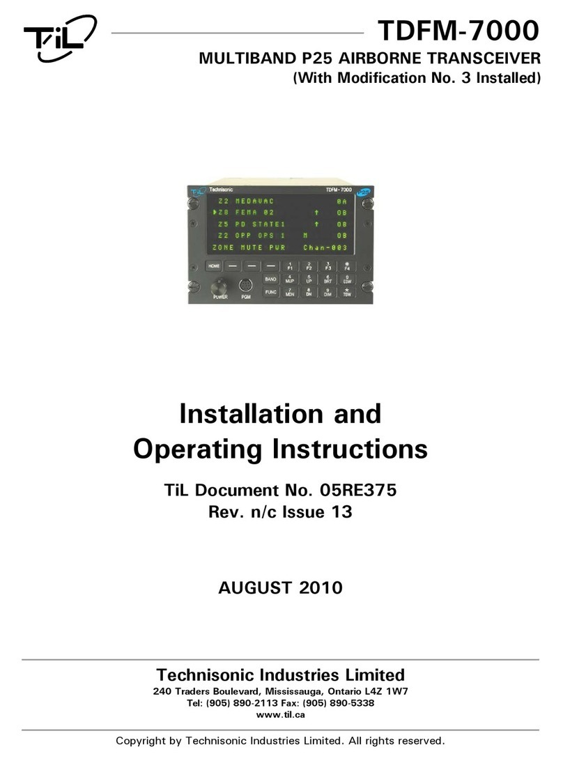
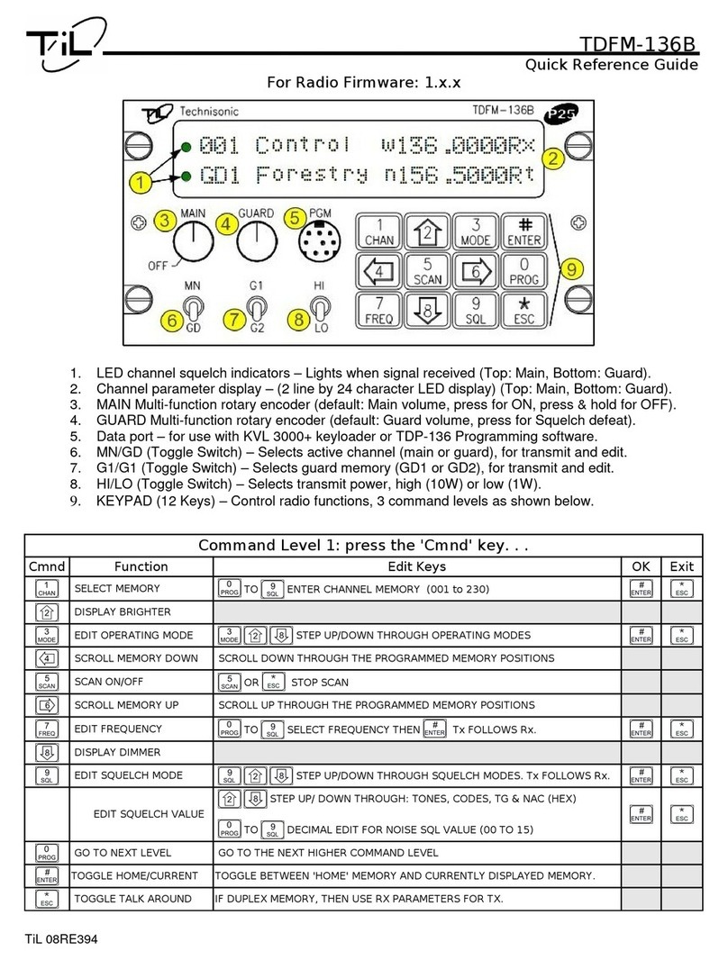
TIL TDFM-136 Manual

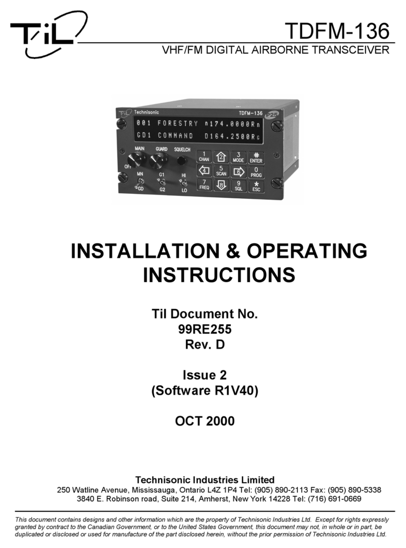
TDFM-136
VHF/FM DIGITAL AIRBORNE TRANSCEIVER
OPERATOR'S GUIDE
Til Document No. 99RE266
Rev. C
(Fo Softwa e Release: 2.0.0)
APR 2004

Table of Contents
SECTION 1 - Introduction 1
1 1 Command Methodology 1
SECTION 2 - Operator Commands 5
2 1 Operator Level 1 Commands 5
L1-1 Select the Operating Memory for the Main Channel (MN) 5
L1-2 Increase Display Brightness 6
L1-3 Edit Channel Operating Mode (MN/GD) 6
L1-4 Scroll Backwards through Available Memories 7
L1-5 Start/Stop Scan (MN) 7
L1-6 Scroll Forward through Available Memories (MN) 8
L1-7 Edit Channel Operating Frequency (MN/GD) 9
L1-8 Decrease Display Brightness 9
L1-9 Edit Channel Squelch Mode (MN/GD) 10
L1-0 Command Level Up 15
2 2 Operator Level 2 Commands 16
L2-1 Create/Edit All Channel Information (MN/GD restricted) 16
L2-2 Copy Guard to Main 18
L2-3 Lock Keypad 19
L2-4 Not Used 19
ii

L2-5 Edit Scan List & Enable/Disable Scan (MN) 19
L2-6 Edit Channel Text Description (MN/GD) 21
L2-7 Create Shadow Channel 22
L2-8 Copy Main to Guard 24
L2-9 Edit Unit ID Value (MN/GD) 24
L2-0 Command Level Up 25
L2–* Command Level Down 25
L2–# Not Used 25
2 3 Operator Level 3 Commands 26
L3-1 Select Boot Channel 26
L3-2 Unused 27
L3-3 Select Hex/Decimal Edit Mode 27
L3-4 Display Software Release and Version Information 28
L3-5 Edit Scan Parameters (MN) 28
L3-6 Configure the PTT Timer 31
L3-7 Side tone Audio Level Adjust 32
L3-8 PC Data Upload/Download 33
L3-9 Display Channel Squelch Parameters 33
L3-0 Command Level Up 34
L3-* Command Level Down 34
L3-# Unused 34
SECTION 3 - Appendix A 35
iii


S E CT I O N 1 - I n t r o d u c t i o n
This section provides the user with a reference of the keypad accessible programming features of the
Technisonic TDFM-136 VHF FM Digital Transceiver
1.1 Command Methodology
This section describes how the TDFM-136 command structure is organized
Command Le els
In order to accommodate the necessary commands, the commands have been divided into
different levels, each command level has up to 12 commands numbered 0-9, # and *; the zero
(0), and the ESC (*) key are functions for every level, they allow the user to move between levels
as follows:
step up through command le els
step down through command le els
When stepping through command levels, the indicated level is shown in subscript in the 4th character
position on the lower line of the display Note that this display position is left blank for the default level
(level1) Table 1 shows the command levels and the associated display character
1

Table 1. Command Le els
Le el Display
Operator L1 blank
Operator L2 ‘2’
Operator L3 ‘3’
The Figure below shows the front panel display for different Command levels
0 0 1 M a i n D 1 3 6 . 0 0 0 0 R g
G D 2 3G u a r d 2 w 1 7 4 . 0 0 0 0 R t
Command Types
There are two basic command types: Inherent and Edit An Inhe ent command is one that requires no
additional input from the user, such as the ‘memory brightness’ or ‘scroll memory’ commands An Edit
command requires further input from the user
Command Scope
Most, but not all, edit commands can affect either the Main or the Guard Channel The channel to be edited
depends on the position of the MN/GD and the G1/G2 front panel switches In this manual, the scope of the
command is given on the command title line as follows:
2

(MN/GD) for a command that is valid in both Main and Guard,
(MN) for a command that is valid for Main only
Blank for a command that is not subject to channel restrictions
Command Con entions
After selecting the command, the system expects further input from the user All edit commands may be
terminated in the same way:
accept the entry and return
abandon the entry and exit
The commands that allow the user to choose an option from a list, will always use the up/down arrows:
(key2 and key8) to step UP and DOWN – respectively - through the available choices In addition, the key
that was used to enter the function can be used to step UP through the available choices
Example: the user selects the L1-3 (Op Mode) command, once the user has selected the command they
can press and , to step up, or to step down through the choices The
advantage of the 'entry key' step method is that the user does not have to move their finger to
a different key to make the choice once the command has been selected
3

Command Reference
Table 2 below shows the commands divided into command levels: one, two, and three
Table 2. Command Le el Reference
Key Le el 1 Le el 2 Le el 3
1 CHAN Select Main Memory Program New Memory Select Boot Memory
2 up Display – Brighter Copy Guard to Main n/u
3 MODE Edit Mode Lock Keypad Select HEX/Decimal Edit
4 back Scroll Memory Down n/u Display Software rev
5 SCAN Scan ON/OFF Edit Scan Set Scan Parameters
6 fwd Scroll Memory Up Edit Description Set PTT Timer
7 FREQ Edit Frequency Create Shadow Channel Set Side-tone Audio
8 down Display – Dimmer Copy Main to Guard PC Communications
9 SQL Edit Squelch Set Unit ID Display Squelch Values
0 PROG Go to next level Go to next level n/u
# ENTER n/u n/u n/u
* ESC n/u Go to Previous level Go to Previous level
NOTE: n/u indicates command keys that are not currently implemented
4

S E CT I O N 2 - O p e r a t o r C o m m a n d s
This section lists the commands available to the user, They are organized into three (3) levels
2.1 Operator Le el 1 Commands
Level 1 commands are accessed directly from the keypad by pressing the desired command key
The command level indicator will be blank The available commands are described below:
L1-1. Select the Operating Memory for the Main Channel (MN)
This command allows the user to select the MAIN channel that the radio is operating on Upon selecting
this command the cursor will appear at the first digit in the channel number as shown:
0 0 0
E n t e r N u m b e r ( 0 - 9 , # * )
Now, select a number from 001 to 230 as follows:
to decimal mode: enter number, cursor automatically ad ances
accept the entry and return
abandon the entry and exit
5

Note: If the channel number selected is out of range then the cursor will remain until the user enters a
valid number If there is no information programmed for the channel, the editor will return to the
previously displayed channel
L1-2. Increase Display Brightness
Press and hold the up arrow (2) key to increase the brightness of the LED display, it stops at maximum
L1-3. Edit Channel Operating Mode (MN/GD)
This command will edit the Operating Mode of the selected channel, the available modes are shown in table
3 Upon selecting this command the cursor will appear at the MODE position:
0 0 1 M a i n D 1 3 6 . 0 0 0 0 R g
E d i t M o d e ( ↑ ↓ 3 , # * )
You may now edit the Operating Mode as follows:
step through the a ailable entries
accept the entry and return
abandon the entry and exit
6

Table 3 Channel Operating Modes
Operating Mode Indicator
Analog Wide (25 kHz) >w=
Analog Narrow (12 5 kHz) >n=
Digital (12 5 kHz) >D=
Note: If an Operating Mode is selected that is incompatible with the current Squelch Mode, then the
Squelch mode will automatically be changed to one that is acceptable for that Operating Mode
(ie >x' for analog, 'm' for Digital Rx and 'g' for Digital Tx)
L1-4. Scroll Backwards through A ailable Memories
This command will scroll the Main Channel BACK, or down, through the programmed memories until
reaching the lowest memory programmed, it will then wrap around and restart from the top Once the user
releases the button the displayed characteristics will be programmed The scroll speed will increase as the
button is held
L1-5. Start/Stop Scan (MN)
This command allows the user to start and stop Scan operation, the system will scan the channels that are
in the same scan list that the currently displayed Main channel is a member of Note that the channels in
the scan list must have scan enabled (see command L2-5) to be scanned If the memory scan has been
enabled then the following screen appears:
7

0 0 1 1M a i n D 1 3 6 . 0 0 0 0 R g
G D 1 ∩G u a r d 1 n 1 5 4 . 0 0 0 0 R t
Once scan has started the scan list digit flashes to indicate that the unit is in SCAN mode Also note that
the key level indicator position has the lock symbol (∩, this indicates that all keypad keys are disabled
except for:
stop scan
display brightness
Front panel switch operation is modified as well: operation of MN/GD or G1/G2 will terminate scan and
restore normal operation of keys and switches The front panel Squelch button is disabled The HI/LO
power switch is unaffected If you try to start scan on a channel or memory that doesn't support scan, you
will see:
0 0 1 M a i n D 1 3 6 . 0 0 0 0 R g
E r r o r : N o n - S c a n n e d C h a n
L1-6. Scroll Forward through A ailable Memories (MN)
This command will scroll FORWARD, or up, through the programmed channels, scroll speed will increase
as the button is held and the scroll will wrap around and restart from the bottom Once the user releases the
button the displayed characteristics will be programmed
8

L1-7. Edit Channel Operating Frequency (MN/GD)
This command allows the user to edit the Operating Frequency of the selected channel The
frequency will be edited in duplex mode: first Receive, then Transmit Once the receive parameter is
entered, the 2nd last chartacter in the display will switch from “R” to “T”, the user can now enter the transmit
value Note that the receive value is automatically entered, so to get simplex operation, simply accept this
entry The edit screen appears as follows:
0 0 1 M a i n D 1 3 6 . 0 0 0 0 R g
E d i t F r e q u e n c y ( 0 - 9 , # * )
Upon start, the cursor appears at the second character in the Frequency field of the channel to be edited
The user may now enter the desired operating frequency as follows:
to decimal mode: enter number, cursor automatically ad ances
accept the entry and return
abandon the entry and exit
The editor will not accept a value outside the limits of 136 0000 MHz to 174 0000 MHz In addition
frequency selection is limited to 2 5 kHz increments in all Operating modes
L1-8. Decrease Display Brightness
Press and hold the down arrow (8) key to decrease the brightness of the LED display, it stops at minimum
9

L1-9. Edit Channel Squelch Mode (MN/GD)
This command will edit the Squelch Mode of the selected channel, and then allow the user to edit the
associated Squelch Mode Value As with the Frequency Edit function above, the Squelch Edit is in duplex
mode, Receive followed by Transmit The edit screen appears as follows:
0 0 1 M a i n D 1 3 6 . 0 0 0 0 R g
E d i t S q l M o d e ( ↑ ↓ 9 , # * )
Upon start, the cursor appears at the Squelch Mode indicator position of the channel to be edited The user
may now select the desired Squelch mode from the list, as follows:
step up through a ailable Squelch modes (see table below)
step down through a ailable Squelch modes
accept the entry and return
abandon the entry and exit
The available options are constrained by the operating mode, that is, different Squelch Modes are available
for the analog Operating Modes (wide and narrow) than for the P25 operating mode See table 4 below
10

Table 4. Recei e and Transmit Squelch Modes
Analog
Rx
Analog
Tx
Digital
Rx
Digital
Tx
Noise
Rx
None
Tx
TalkGroup + NAC
Rg
TalkGroup + NAC
Tg
CTCSS Tones
Rt
CTCSS Tones
Tt
NAC Only
Rn
ID Call
Ti
DCS Code
Rc
DCS Codes
Tc
Monitor
Rm
Inhibit
T-
Inhibit
T-
Once the Squelch Mode has been selected, the user will be allowed to edit the value of the selected mode
The Squelch Modes that may be edited are: Noise, CTCSS Tones, and DCS Codes for analog operating
modes, and TalkGroup, NAC, and ID Call for digital operating mode
L1-9.1 Edit Noise Squelch Value analog only, receive only, range 0-16
If Noise (Rx) is chosen, the prompt line will display the current value for noise squelch level and place the
cursor on the first digit, the value can be edited using the keys shown below
0 0 5 T e s t n 1 5 6 . 0 0 0 0 R x
N o i s e L e e l : 1 0
to decimal mode: enter number, cursor automatically ad ances
accept the entry and return
abandon the entry and exit
11

L1-9.2 Select CTCSS Tone analog only, receive & transmit, 42 tones (67Hz to 254 8Hz)
If CTCSS Tones are chosen, the prompt line will display the current value for that tone, the user can select
the tone using the keys shown below Appendix A lists the available tones
0 0 5 T e s t n 1 5 6 . 0 0 0 0 R t
C T C S S T o n e ( ↑↓, # * ) : 6 7 . 0
step up/down through a ailable CTCSS Tones
accept the entry and return
abandon the entry and exit
L1-9.3 Select DCS Code Scope: analog only, receive only, 83 codes (23 to 754)
If DCS Codes are chosen, the prompt line will display the current value for that code, the user can select
the code using the keys shown below Appendix A lists the available choices
0 0 5 T e s t n 1 5 6 . 0 0 0 0 R c
D C S C o d e ( ↑↓, # * ) : 2 3
step up/down through a ailable DCS Codes
accept the entry and return
abandon the entry and exit
12

L1-9.4 Edit P oject 25 Talkg oup Value digital only, receive & transmit, range 0-65535 ($0000-$FFFF)
If the P25 TalkGroup was chosen the, the prompt line will display the current TalkGroup value, the cursor
will be on the first digit:
0 0 1 M a i n D 1 3 6 . 0 0 0 0 R g
P 2 5 T a l k G r o u p : 0 0 0 1
This parameter may be edited in either HEX or in Decimal (see command L3-3) The edit keys are as
follows:
hex edit: step up/down through hex digits (0-9, A-F)
hex edit: mo e cursor forward / backward
to decimal mode: enter number, cursor automatically ad ances
accept the entry and return
abandon the entry and exit
Note: If P25 Talkgroup was chosen, the editor will proceed to Edit NAC upon accepting the Talkgroup
value
13

L1-9.5 Edit P oject 25 NAC Value Scope: digital only, receive and transmit, range 0-4095 ($000-$FFF)
If the P25 NAC was chosen (or after entering the P25 TalkGroup) the prompt line will display the current
NAC value, with the cursor on the first digit:
0 0 1 M a i n D 1 3 6 . 0 0 0 0 R n
P 2 5 N A C : 0 0 1
This parameter may be edited in either HEX or in Decimal (see command L3-3) The edit keys are as
follows:
hex edit: step up/down through hex digits (0-9, A-F)
hex edit: mo e cursor forward / backward
to decimal mode: enter number, cursor automatically ad ances
accept the entry and return
abandon the entry and exit
L1-9.6 Edit P oject 25 ID Call Value - Scope: digital only, transmit only, range 0-9,999,999
If the P25 ID Call is chosen, the prompt line will display the current ID Call value This parameter may only
be edited in decimal, as follows:
14

0 0 1 M a i n D 1 3 6 . 0 0 0 0 T i
P 2 5 C a l l U n i t # : 0 0 0 0 0 0 1
This transmit only mode allows the user to try to contact a specific radio by transmitting that radio's user ID
If no radio has that ID then this will fail
The keys used to edit the ID call parameter are:
to decimal mode: enter number, cursor automatically ad ances
accept the entry and return
abandon the entry and exit
L1–0. Command Le el Up
This key selects the next HIGHER Command Level, the Command Level is indicated by a subscript digit in
the 4th character position on the lower row of the display See table 2-1
Upon pressing this key, the radio will remain in the new Command Level for 5 seconds, if there is no further
user input within this time then the radio will revert to Level 1 The Direct Command Level (level 1) is the
normal operating mode for the radio and is indicated by a blank space
L1. Not Used
15

2.2 Operator Le el 2 Commands
Access the Level 2 Commands by pressing the >PROG= key from the Ope ato Level 1 once, the Menu
Level indicator will show a subscript >2=
Note: the system is time limited in command levels above level 1 The system will automatically return
to level 1 if a command has not been selected in five (5) seconds!
L2–1. Create/Edit All Channel Information (MN/GD restricted)
This command allows the user to create a new memory position (for Main channel only) or to edit all the
parameters of an existing memory position (Main or Guard channels) The editor steps through the channel
parameters in sequence from left to right across the screen The edit functions here match those used to
edit an individual parameter; in this case however selecting the ENTER key accepts the data and proceeds
to the next step, rather than returning Only after the last step does selecting enter save the data and exit
The ESC key will abandon the entire edit session without changing an existing channel or creating a new
one
accept the entry and return
abandon the entry and exit
16
Other manuals for TDFM-136
2
Table of contents
Other TIL Transceiver manuals
