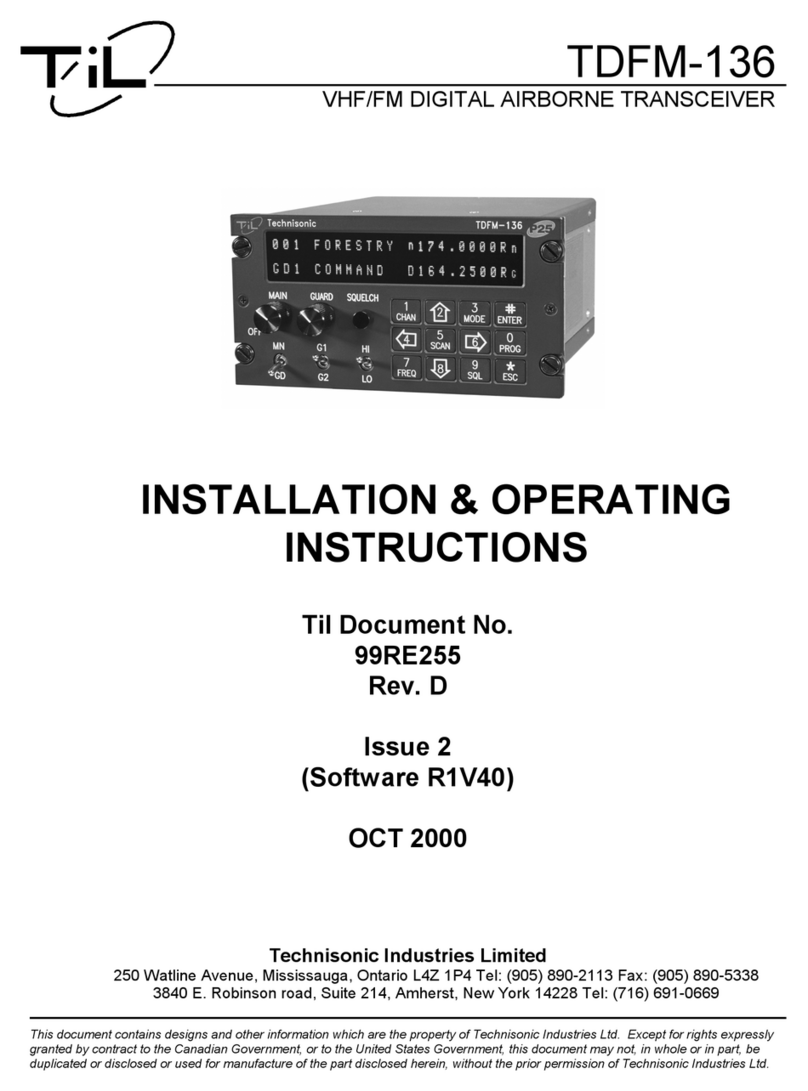
TIL TDFM-136 Manual

TDFM-136(A)
VHF/FM DIGITAL AIRBORNE TRANSCEIVER
OPERATOR'S GUIDE
Til Document No. 99RE266
Rev. E
(For So tware Release: 3.x.x)
JUN 2011

Table of Cont ents
SECTION 1 - Introdu tion to Commands...................................................................................................1
1.1 Command Levels............................................................................................................................ 1
1.2 Command Types.............................................................................................................................2
1.3 Command S ope............................................................................................................................3
1.4 Command Referen e......................................................................................................................4
SECTION 2 - Operator Commands...........................................................................................................5
2.1 Operator Level 1 Commands..........................................................................................................5
L1-1. Sele t the Operating Memory for the Main Channel (MN)......................................................5
L1-2. In rease Display Brightness...................................................................................................6
L1-3. Edit Channel Operating Mode (MN/GD).................................................................................6
L1-4. S roll Ba kwards through Available Memories.......................................................................7
L1-5. Start/Stop S an (MN).............................................................................................................7
L1-6. S roll Forward through Available Memories (MN)..................................................................8
L1-7. Edit Channel Operating Frequen y (MN/GD).........................................................................8
L1-8. De rease Display Brightness..................................................................................................9
L1-9. Edit Channel Squel h Mode (MN/GD)....................................................................................9
L1-0. Command Level Up..............................................................................................................13
L1-#. Toggle Main Memory: Home/Current (MN)...........................................................................13
L1-*. Toggle Talk Around (MN)......................................................................................................13
2.2 Operator Level 2 Commands........................................................................................................14
L2-1. Create/Edit All Channel Information (MN/GD restri ted).....................................................14
ii

L2-2. Copy Guard to Main ............................................................................................................17
L2-3. Lo k Keypad ........................................................................................................................17
L2-4. Not Used..............................................................................................................................17
L2-5. Edit S an List & Enable/Disable S an (MN).........................................................................18
L2-6. Edit Channel Text Des ription (MN/GD)...............................................................................19
L2-7. Create Shadow Channel.......................................................................................................20
L2-8. Copy Main to Guard ............................................................................................................22
L2-9. En ryption ON/OFF (MN/GD)...............................................................................................22
L2-0. Command Level Up .............................................................................................................22
L2-*. Command Level Down..........................................................................................................22
2.3 Operator Level 3 Commands........................................................................................................24
L3-1. Sele t Boot Memory.............................................................................................................24
L3-2. Assign Key by Key Tag........................................................................................................25
L3-3. Sele t Hex/De imal Edit Mode.............................................................................................27
L3-4. Display Software Release and Version Information.............................................................27
L3-5. Edit S an Parameters (MN)..................................................................................................28
L3-6. Configure the PTT Timer......................................................................................................30
L3-7. Side tone Audio Level Adjust................................................................................................31
L3-8. PC Data Upload/Download ..................................................................................................31
L3-9. Display Channel Squel h Parameters..................................................................................32
L3-0. Command Level Up .............................................................................................................32
L3-*. Command Level Down..........................................................................................................32
SECTION 3 - Appendix A........................................................................................................................33
iii

S E C T I O N 1 - I n t r o d u c t i o n t o C o m m a n d s
This se tion provides the user with a referen e of the keypad a essible programming features
of the Te hnisoni TDFM-136(A) VHF FM Digital Trans eiver.
1.1 Command Levels
In order to a ommodate the ne essary ommands, the ommands have been divided into different levels,
ea h ommand level has up to 12 ommands numbered 0-9, # and *; the zero (0), and the ESC (*) key are
fun tions for every level, they allow the user to move between levels as follows:
step up through command levels
step down through command levels
When stepping through ommand levels, the indi ated level is shown in subs ript in the 4th hara ter
position on the lower line of the display. Note that this display position is left blank for the default level
(level1). Table 1 shows the hara ter for ea h ommand level, the a ompanying figure shows the level
hara ter position:
Table 1. Command Levels
Level isplay
Operator L1 blank
Operator L2 ‘2’
Operator L3 ‘3’
1

1.2 Command Types
There are two basi ommand types: Inherent and Intera tive. An Inherent ommand is one that requires
no additional input from the user, su h as the ‘memory brightness’ or ‘s roll memory’ ommands. An
Interactive ommand requires further input from the user.
Inherent commands
These are simple 'one-tou h' ommands, they do not need any further input from the user.
Interactive commands
These ommands require further input from the user, and they must end as follows:
accept the entry and exit
abandon the entry and exit
The ommands that allow the user to hoose an option from a list, will always use the up/down arrows:
(key2 and key8) to step UP and DOWN – respe tively - through the available hoi es. In addition, the key
that was used to enter the fun tion an be used to step UP through the available hoi es.
Example: the user sele ts the L1-3 (Op Mode) ommand, on e the user has sele ted the ommand they
an press and , to step up, or to step down through the hoi es. The
advantage of the 'entry key' step method is that the user does not have to move their finger to
a different key to make the hoi e on e the ommand has been sele ted.
2

1.3 Command Scope
Most, but not all, edit ommands an affe t either the Main or the Guard Channel. The hannel to be edited
depends on the position of the MN/GD and the G1/G2 front panel swit hes. In this manual, the s ope of the
ommand is given on the ommand title line as follows:
(MN/GD) for a ommand that is valid for both Main and Guard,
(MN) for a ommand that is valid for Main only
Blank for a ommand that is not subje t to hannel restri tions.
3

1.4 Command Reference
Table 2 below shows the ommands divided into ommand levels: one, two, and three.
Table 2. Command Level Reference
Key Level 1 Level 2 Level 3
1 CHAN Sele t Main Memory Program New Memory Sele t Boot Memory
2 up Display – Brighter Copy Guard to Main Set En r key by KeyTag
3 MODE Edit Operating Mode Lo k Keypad Sele t HEX/De imal Edit
4 ba k S roll Memory Down n/u Show Firmware Revision
5 SCAN S an ON/OFF Edit S an Set S an Parameters
6 fwd S roll Memory Up Edit Des ription Set PTT Timer
7 FREQ Edit Frequen y Create Shadow Channel Set Side-tone Audio
8 down Display – Dimmer Copy Main to Guard PC Communi ations
9 SQL Edit Squel h Mode Enable/Disable En ryption Display Squel h Values
0 PROG Go to next level Go to next level Go to next level
# ENTER Toggle Memory: Home/ urrent Set 'Home' memory. n/u
* ESC Toggle Talk Around Go to Previous level Go to Previous level
2+4+6 Emergen y Erase Keys n/u n/u
NOTE: n/u indi ates ommand keys that are not urrently implemented.
4

S E C T I O N 2 - O p e r a t o r C o m m a n d s
This se tion des ribes the ommands available to the user, they are organized into three (3)
levels (L1-L3). Current level is indi ated by 4th hara ter on bottom row: blank=L1, 2=L2, 3=L3.
2.1 Operator Level 1 Commands
Level 1 ommands are a essed dire tly from the keypad by pressing the desired ommand key.
The ommand level indi ator will be blank. The available ommands are des ribed below.
L1-1. Select the Operating Memory for the Main Channel (MN)
This ommand allows the user to sele t the memory for MAIN hannel operation.
The ursor appears at the first digit in the hannel
number.
Valid edit keys are:
to Enter digit, cursor automatically
advances and wraps
accept the entry and continue
abandon the entry and exit
Note: The user must enter the number for an existing memory (in the range 001 to 230). If the memory
does not exist, the editor will return to the previously displayed memory.
5
!"#

L1-2. Increase isplay Brightness
Press and hold the up arrow (2) key to in rease the brightness of the LED display, it stops at maximum.
L1-3. Edit Channel Operating Mode (MN/G )
This ommand will edit the Operating Mode of the sele ted hannel, the available modes are shown in table
3. Upon sele ting this ommand the ursor will appear at the MODE position:
Valid edit keys are:
step up through available operating modes
(w, n, )
Table 3 Operating Modes
Operating Mode Indicator
Analog Wide (25 kHz) 'w'
Analog Narrow (12.5 kHz) 'n'
Digital (12.5 kHz) 'D'
step down through available operating modes
(w, n, )
accept the entry and continue
abandon the entry and exit
Note: If an Operating Mode is sele ted that is in ompatible with the urrent Squel h Mode, then the
Squel h mode will automati ally be hanged to one that is a eptable for that Operating Mode
(ie 'x' for analog, 'm' for Digital Rx and 'g' for Digital Tx).
6
$%&'
(&$()* !"#

L1-4. Scroll Backwards through Available Memories
This ommand will s roll the Main Channel BACK, or down, through the programmed memories until
rea hing the lowest memory programmed, it will then wrap around and restart from the top. On e the user
releases the button the displayed hara teristi s will be programmed. The s roll speed will in rease as the
button is held.
L1-5. Start/Stop Scan (MN)
S an memories that are in the same s an list as the urrently displayed Main memory. S an must be
enabled for the memory to be s anned, if so on e s an starts, the s an list digit flashes to indi ate that the
unit is in SCAN mode. The lo k symbol, this indi ates that most keypad keys are disabled.
DurIng s an: S an digit flashes, lo k indi ator shown. Valid keys are:
Stop scan
change display brightness
Swit h operation is modified as well: operation of MN/GD or G1/G2 will terminate scan and restore normal
operation. The front panel Squelch De eat button is disabled. The HI/LO power swit h is unaffe ted.
If you try to start s an on a hannel or memory that doesn't support s an, you will see:
7
+$%&'
,-%(.%
+$%&'
/%(0

L1-6. Scroll Forward through Available Memories (MN)
This ommand will s roll FORWARD, or up, through the existing hannels, s roll speed will in rease as the
button is held and the s roll will wrap around and restart from the bottom. On e the user releases the button
the displayed hara teristi s will be programmed.
L1-7. Edit Channel Operating Frequency (MN/G )
Edit the Operating Frequency of the sele ted hannel. The frequen y will be edited first Re eive, then
Transmit. On e the re eive parameter is entered, the 2nd last hara ter in the line will swit h from “R” to “T”,
the user an now enter the transmit value. The editor will operate a ording to the urrent frequen y mode,
that is: If the frequen y is urrently simplex, then the edit will ontinue in simplex mode (the value entered
for re eive will automati ally be arried to transmit), if the frequen y is urrently duplex, then the edit will
ontinue in duplex mode (the re eive value will not be automati ally arried to transmit).
The editor will not a ept a value outside the limits of 136.0000 MHz. to 174.0000 MHz. In addition
frequen y sele tion is limited to 2.5 kHz in rements and valid 6.25kHz frequen ies in all Operating modes.
The ursor appears at the se ond hara ter in the
Frequen y field of the hannel to be edited.
Valid edit keys are:
to Enter digit, cursor automatically
advances and wraps
accept the entry and continue
abandon the entry and exit
8
$%&
(&1- !"#

L1-8. ecrease isplay Brightness
Press and hold the down arrow (8) key to de rease the brightness of the LED display, it stops at minimum.
L1-9. Edit Channel Squelch Mode (MN/G )
Edit the Squelch Mode of the sele ted hannel, and then allow the user to edit the asso iated Squel h
Mode Value. The Squel h Edit is in duplex mode, Re eive followed by Transmit.
The ursor is pla ed on the Squel h hara ter. Valid edit keys are:
step up/up/down through available
squelch modes.
accept the entry and continue
abandon the entry and exit
The available options are onstrained by the operating mode, that is, different Squel h Modes are available
for the analog Operating Modes (wide and narrow) than for the P25 operating mode. See table 4 below.
Table 4. Receive and Transmit Squelch Modes
Analog Rx Analog Tx igital Rx igital Tx
Noise CTCSS Tones Monitor TalkGroup + NAC '
CTCSS Tones DCS Codes -NAC Only ID Call &
DCS Code -Inhibit TalkGroup + NAC 'Inhibit
9
(&,1$()* !"#

The Squel h Modes that may be edited are: Noise, CTCSS Tones, and DCS Codes for analog operating
modes, and TalkGroup, NAC, and ID Call for digital operating mode.
Analog - Noise Squelch Value. Scope: re eive only, range 0-16 ($0-$F)
If Noise (Rx) is hosen, the prompt line will display the urrent value for noise squel h level and pla e the
ursor on the first digit available for the user to edit:
Valid edit keys are:
to ecimal mode: enter number, cursor
automatically advances and wraps
accept the entry and continue
abandon the entry and exit
Analog - CTCSS Tone. Scope: re eive & transmit, 42 tones (see appendix 4.2 )
The prompt line displays the urrent CTCSS Tone:
Valid edit keys are:
step up/down through CTCSS tones
accept the entry and continue
abandon the entry and exit
10
&234
2%(%
5,,5)* !"#46

Edit Analog - DCS Code. Scope: re eive & transmit, 83 odes (see appendix 4.2 )
If DCS Codes are hosen, the prompt line will display
the urrent ode value:
Valid edit keys are:
step up/down through CS codes
accept the entry and continue
abandon the entry and exit
Edit P25 Digital - Talkgroup Value. Scope: re eive and transmit, range 0-65535 ($0000-$FFFF)
If the P25 TalkGroup was hosen the, the prompt
line will display the urrent TalkGroup value, the
ursor will be on the first digit:
Valid edit keys are:
hex edit: move cursor backward/forward
through the digits
hex edit: step up/down through the hex
digits (0-9, A-F)
to ecimal mode: enter number, cursor
automatically advances and wraps
accept the entry and continue
abandon the entry and exit
Note: If P25 Talkgroup was hosen, the editor will drop into Edit NAC upon a epting the Talkgroup
value.
11
7(-
,()* !"#48
7('
985%:;4

Edit P25 Digital - NAC Value. Scope: receive and transmit, range 0-4095 ($000-$FFF)
If the P25 NAC was hosen (or after entering the
P25 TalkGroup) the prompt line will display the
urrent NAC value, with the ursor on the first digit:
Valid edit keys are:
hex edit: move cursor backward/forward
through the digits
hex edit: step up/down through the hex
digits (0-9, A-F)
to ecimal mode: enter number, cursor
automatically advances and wraps
accept the entry and continue
abandon the entry and exit
Edit P25 Digital - ID Call Value. Scope: transmit only, range 0-9,999,999
This transmit only mode allows the user to try to onta t a spe ifi radio by transmitting that radio's user
ID. If no radio has that ID then this will fail.
If the P25 ID Call was hosen, the prompt line will
display the urrent ID Call value:
Valid edit keys are:
to ecimal mode: enter number, cursor
automatically advances and wraps
accept the entry and continue
abandon the entry and exit
12
7('
98<4
7(5&
98%=&!4

L1–0. Command Level Up
This key sele ts the next HIGHER Command Level, the Command Level is indi ated by a subs ript digit in
the 4th hara ter position on the lower row of the display. See table 2-1.
Upon pressing this key, the radio will remain in the new Command Level for 5 se onds, if there is no further
user input within this time then the radio will revert to Level 1. The Dire t Command Level (level 1) is the
normal operating mode for the radio and is indi ated by a blank spa e.
L1–#. Toggle Main Memory: Home/Current (MN)
This key toggles between the urrent memory and the designated 'Home” memory for the Main hannel. If
no 'Home' memory has been hosen the system will default to memory 001. he lower row of the display.
See table 2-1.
L1–*. Toggle Talk Around (MN)
This key toggles the Talk Around fun tion on and off. Talk around is indi ated by an up arrow pla ed at the
de imal point position in the frequen y field. When Talk Around is enabled for a duplex memory the
memory uses it's re eive parameters for transmit, and thus fun tions like a simplex hannel. Simplex
hannels are unaffe ted.
13

2.2 Operator Level 2 Commands
A ess the Level 2 Commands by pressing the “PROG" key from the Operator Level 1 on e, the
Menu Level indi ator will show a subs ript “2”. This is a 'timed' level, if a ommand is not sele ted
within 5 se onds the unit automati ally returns to level 1. Upon exit from a ommand the timer is
restarted and you have a further 5 se onds to sele t another ommand on this level. If you wish to
return immediately to level 1 press the 'ESC' (*) key, if you wish to advan e to level 3 press the 'PROG'
(0) key.
L2–1. Create/Edit All Channel Information (MN/G restricted)
This ommand allows the user to reate a new memory position (for Main hannel only) or to edit all the
parameters of an existing memory position (Main or Guard hannels). The editor steps through the hannel
parameters in sequen e from left to right a ross the s reen. The edit fun tions here mat h those used to
edit an individual parameter; in this ase however sele ting the ENTER key a epts the data and pro eeds
to the next step, rather than returning. Only after the last step does sele ting enter save the data and exit..
The ESC key will abandon the entire edit session without hanging an existing hannel or reating a new
one.
accept the entry and continue – exit only after all edits completed.
abandon the entry and exit
14

L2-1.1. Entering a Memory Number (re er to L1-1 or details)
Upon sele ting this ommand, the first step is to enter the number of the memory position that you wish to
Create or Edit, for Main Channel memories, the valid range is (001 to 230).
On e a number has been entered, the system he ks to see if the memory lo ation has already been
programmed, if so, then the existing data will be loaded; if the lo ation has NOT been previously
programmed then the default template data will be loaded. In ea h ase the user an edit the hannel
parameters in the same way as shown in the following steps.
L2-1.2. Enter a Scan Zone & Enabling/Disabling Scan (re er to L2-5 or details)
After entering a MEMORY number the ursor will move to the fourth (4th) position on the top line, the
default s an list is shown in subs ript. If there is a bar over top of the hara ter, this indi ates that s an is
disabled for this memory, if there is no bar, then s an has been enabled. The 'PROG' key (key 0 ) toggles
the s an enabled/disabled state.
L2-1.3. Enter a Text Description (re er to L2-6 or details)
After SCAN, the ursor advan es to the first position in the eight (8) hara ter text des ription field, the user
may now edit the existing text as desired. The editor allows you to sele t all upper and lower (A-Z, a-z) ase
alphabeti hara ters, the numbers from zero to nine (0-9), and a sele tion of extra hara ters in luding the
spa e.
L2-1.4. Enter an Operating Mode (re er to L1-3 or details)
After TEXT, the ursor advan es on the one (1) hara ter Operating Mode (Mode) field, this single
hara ter represents the operation of the radio: analog wide, analog narrow, or digital.
15

L2-1.5. Enter a Frequency (re er to L1-7 or details)
After MODE, the ursor advan es to the frequen y parameter field, this is a seven (7) digit de imal
parameter, though the first digit is always one so the user annot edit that digit. The frequen y parameter
may be edited to any number between 136.0000 and 174.0000 in 2.5 kHz. steps. (ie 150.0025 is valid,
150.0046 is not), or frequen ies in the 6.25kHz plan (see appendix D)
The frequen y will be edited first Re eive, then Transmit; on e the re eive parameter is entered, the 2nd last
hara ter in the line will swit h from “R” to “T”, the user an now enter the transmit value. The editor will
operate a ording to the urrent frequen y mode, that is: when you start editing if the frequen y is urrently
simplex (Rx and Tx frequen ies are the same), then the edit will ontinue in simplex mode (the value
entered for re eive will automati ally be arried to transmit). If the frequen y is urrently duplex (Rx and Tx
frequen ies are different), then the edit will ontinue in duplex mode (the re eive value will not be
automati ally arried to transmit).
L2-1.6. Enter the Squelch Parameters (re er to L1-9 or details)
After FREQUENCY, the ursor advan es to the Squel h Mode field. A single hara ter field shows the
Squel h Mode sele ted. This is a duplex parameter so a different mode an be hosen for transmit than
was hosen for re eive. Note that the modes available will be restri ted by the Operating Mode (ie the
modes available are different for analog and digital operation).
On e the user is finished and sele ts ‘ENTER’ then the newly edited hannel parameters are sele ted and
displayed for the appropriate hannel. This may take a moment as the information is programmed into the
appropriate RF module at this time as well.
16

L2–2. Copy Guard to Main
Copy the urrently displayed Guard information UP to the Main hannel. This is irreversible, so be sure you
wish to do this. As a safety pre aution this ommand is disabled from the fa tory.
L2-3. Lock Keypad
This ommand lo ks the keypad to prevent a idental hange to parameters of the radio unbeknownst to
the operator. This will disable all keyboard fun tions (ex ept keyboard unlo k and display luminan e).
Edit Keys
Lock the keypad, display 'locked' until key release.
Unlock the keypad (after 2 seconds), display 'unlocked' until key release.
L2–4. Not Used.
17
Other manuals for TDFM-136
2
This manual suits for next models
1
Table of contents
Other TIL Transceiver manuals
