TileVision TV/23/FR2/PS User manual

Operating Instructions
PORTER LANCASTRIAN
PORTER LANCASTRIAN LIMITED
www.tilevision.tv
TileVision®is Designed and Manufactured by:
23
®

23" Widescreen TileVision®
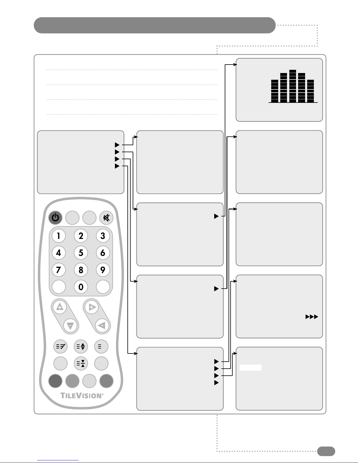
A Wide Array of Screen Settings
You can choose different screen settings depending on the type of programme you are
watching or the surrounding conditions (the lighting or the outside weather conditions).
You can switch between Dynamic, Standard, Mild and Game Options, or you can
configure the screen settings yourself. You can select various picture formats; 16:9,
14:9, 4:3, 16:9 Zoom, 14:9 Zoom, 4:3 Zoom or Auto, to match the content you are
watching to your preference.
A Wide Array of Sound Settings
You can choose an optimal sound setting for the type of program you are watching.
You can switch between Flat, Music, Movie, and Speech, or you can configure
the settings yourself.
Quick View
Press the QV button to view the last programme you were watching.
Teletext Function
You can display teletext information at any time on your TileVision®.
FM Radio Function
Tune in to your favourite FM radio stations by selecting the Radio Mode.
This symbol is intended to alert the user to the presence of important
operating and maintenance (servicing) instructions in the literature
accompanying the appliance.
CAUTION
RISK OF ELECTRIC SHOCK
DO NOT OPEN
WARNING: TO PREVENT INJURY, THIS APPARATUS MUST BE
SECURELY ATTACHED TO THE WALL IN ACCORDANCE
WITH THE INSTALLATION INSTRUCTIONS.
CAUTION: DO NOT REMOVE COVER.
NO USER-SERVICEABLE PARTS INSIDE.
REFER SERVICING TO QUALIFIED SERVICE PERSONNEL.
BEWARE OF STATIC SENSITIVE PARTS.
Waste Electrical and Electronic Equipment (WEEE) Directive
In the European Union, this symbol indicates that this product should
not be disposed of with household waste. It should be deposited at an
appropriate facility to enable recovery and recycling.
1
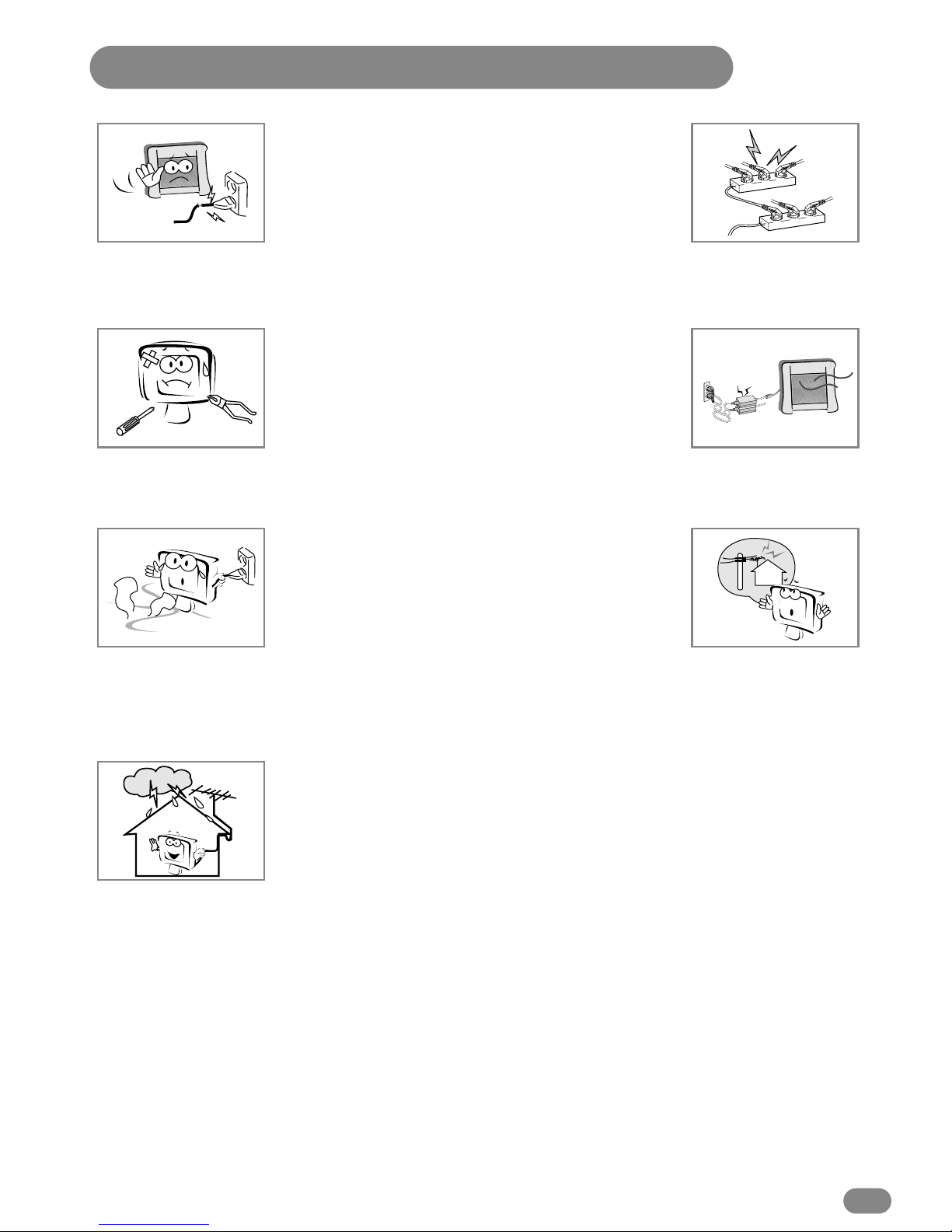
Safety Instructions
Do not use a damaged socket and do not let the power cord
touch a heat source.
–This may cause an electric shock or fire.
Do not attempt to service the unit.
Contact an authorised dealer or repair service.
–Servicing the unit yourself may cause an electric shock or fire.
If there are any unusual sounds or smells coming from the
unit, unplug it immediately and contact an authorised
dealer or repair service.
–This may cause an electric shock or fire.
If an outside antenna is connected to the unit, ensure the
external to internal cable entry is fully sealed
–This may cause an electric shock or fire.
Do not connect too many extension cords or plugs to
an outlet.
–This may cause a fire.
Keep the power adaptor away from any heat source.
–This may cause a fire.
Ensure the antenna is located away from overhead cables.
–This may cause an electric shock.

2
Tools Required
Suction Lifter
Silicone Sealant Isopropyl Alcohol
I
s
o
p
r
o
p
y
l
A
l
c
o
h
o
l
Soft Cloth
☛
Silicone Sealant produces acetic acid during cure.
Use only in well ventilated areas. Irritating to eyes.
Wash hands after use and before meals. Wash
splashes from skin, clothing and other surfaces. Use
a clean cloth. In case of contact with eyes wash
immediately with plenty of water.
Please observe safety precautions on the container.
Keep out of reach of children and animals.
☛
Isopropyl alcohol is available from most pharmacies
and larger electronics wholesalers. It is an effective
degreasing agent.
Please observe safety precautions on the container.
Keep out of reach of children and animals.
Do not drink.
HIGHLY
FLAMMABLE
IRRITANT
IRRITANT

Table of Contents
3
Safety Instructions ......................................................................................................................................................1
Tools Required ..............................................................................................................................................................2
Unpacking your TileVision®......................................................................................................................................4
Your TileVision®............................................................................................................................................................5
Connector Inputs ..........................................................................................................................................................5
Connections ....................................................................................................................................................................6
Connecting an Antenna or Cable ..........................................................................................................................7
Connecting to the S-Video, PC/DTV and PC/DVI Inputs ..............................................................................8
Connecting to the SCART Inputs ..........................................................................................................................9
Installing the Front Plate ........................................................................................................................................10
The Remote Control ..................................................................................................................................................11
Switching the TileVision®On/Off ..........................................................................................................................12
Selecting a Picture from External Sources ......................................................................................................12
Selecting your On-screen Language ..................................................................................................................12
On-screen Menus and Displays ..........................................................................................................................13
Tuning, Setup and Editing Programs ................................................................................................................14
Picture Control ............................................................................................................................................................18
Sound Control ............................................................................................................................................................19
PC Picture Adjustment ............................................................................................................................................21
PC Sound Adjustment ..............................................................................................................................................23
Clock ..............................................................................................................................................................................24
Blue Back ......................................................................................................................................................................24
Auto Sleep ....................................................................................................................................................................25
Child Lock ....................................................................................................................................................................25
Radio ..............................................................................................................................................................................25
ARC (Aspect Ratio Control) ..................................................................................................................................26
Radio Tuning and Setup ........................................................................................................................................27
Calling the Programme List ....................................................................................................................................28
Picture in Picture ........................................................................................................................................................29
Teletext ..........................................................................................................................................................................30
Displaying the Teletext Information ....................................................................................................................30
Teletext Button Functions ......................................................................................................................................31
Troubleshooting ..........................................................................................................................................................32
Specifications ..............................................................................................................................................................33

Unpacking your TileVision®
4
Please make sure the following items are
included with your TileVision®.
1
TileVision®glass front plate assembly –complete with Velcro
fixing strips.
1
waterproof remote control.
1
standard full function remote control.
1
installation and instruction manual.
1
mirror acrylic surround.
1
remote control holder.
If any items are missing, contact your dealer.

Your TileVision®
5
Front View
Remote control sensor and indicator
Power Indicator Status
Connector Inputs
DC24V Power Input
PC/Digital Input (DVI-I)
Headphone Output
PC Audio Input
PC/Analog Input (D-SUB)
EURO-SCART 1 (Full: RGB, FB, AV In, AV Out)
EURO-SCART 2 (Half: AV In, AV Out)
Audio Inputs (R, L (Mono))
S-VIDEO Input
Antenna Input
1 2 3 4 5 6 7 8 9 10
1
2
3
4
5
6
7
8
9
10
EURO-SCART 1
(RGB, FB, AV –In/Out) EURO-SCART 2
(AV –In/Out)
AntennaPC/Digital
(DVI-I) Phones PC
Audio
S-Video
In
PC/Analog
(D-SUB)
24VDC
L
(Mono)
Audio In
R
Status
Stand-by
Power on
Remote control
Indicator
Red
Green
Red blinking
Connections
6
Earthing Points
The Earthing connection points are found on the rear of the front plate and are clearly marked
with green labels. Connect the earthing cables from the back box to these points.
Power Socket
The Power socket (1) is located at the extreme left of the connection array.
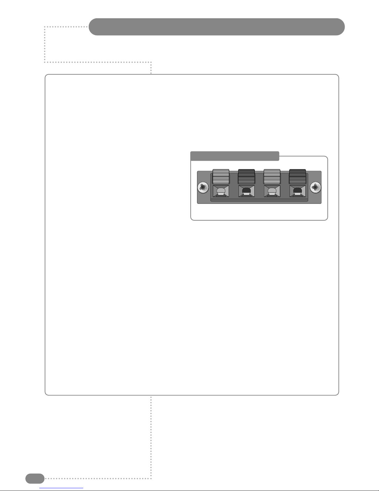
Speaker Connections
The speakers should be connected after the
Earth straps to the rear of the front plate as
detailed on page 10 of these operating
instructions.
The speaker connection block is found on the
right of the rear of the front plate. Lift one of
the lugs, push one conductor of the speaker
lead into the connector, release the lug and
give the lead a slight pull to make sure that it
is gripped correctly. The other wires are connected in the same way.
Note: To ensure that the speakers are in correct phase, the conductor with the stripe should be
connected to the negative terminal (L–or R–) and the plain conductor should be connected to the
corresponding positive terminal (L+ or R+).
Connections to the speakers terminals should be made in the same way –striped conductor to
the negative terminal and plain conductor to the positive terminal.
Antenna Feed
The Antenna input jack is found at the extreme right of the connection array (refer to page 7). A
minimum signal level of 60dBu/1mV is required to avoid a noisy picture.
Additional connections
Connectors for; PC Digital (DVI-I), Headphones, PC Analog (D-SUB), SCART1 (Full), SCART2
(Half), Audio, and S-Video are found in the central portion of the connection array. If these inputs
are to be utilised the necessary cables must be installed at the same time as the back box (refer
to pages 8 and 9 of these instructions).
Note: Careful consideration should be given to use of these inputs prior to the installation
of the unit.
Speaker Connection Block
L–L+ R+ R–

7
or
Cable Television
Network
Rear of the
TileVision
®
Antenna
Connecting an Antenna or Cable
To view television channels correctly, a signal must be received by the set from one of
the following sources: an outdoor antenna, a cable television system or a satellite dish.
☛
The signal level fed to the set must be at least
60dBu/1mV or the picture may be noisy.
If in doubt, consult a qualified aerial technician.
All connections must be made before sealing the
front plate into the back box.
1
Connect the antenna or input cable to the 75Ωcoaxial input on
the rear of the TileVision®.
2
If you are using an indoor antenna, you may need to turn it
when tuning your television until you receive a clear picture.
8
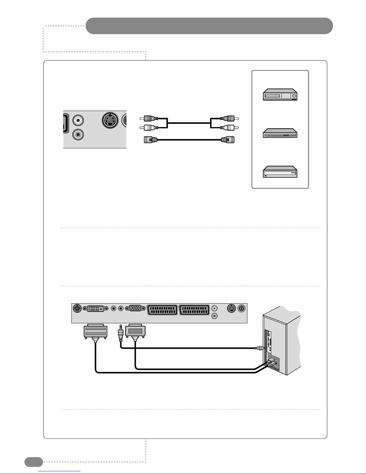
Connecting to the S-Video, PC/DTV and PC/DVI Inputs
S-Video Input (above)
1
Connect the S-Video/RCA (audio L/R) cable to the input jacks on the TileVision®and output jacks
on the external equipment such as a VCR, DVD and some video game consoles.
2
If the external equipment has mono audio output, connect it only to left jack of the Audio
Input/Output.
PC/DTV Input (below)
1
Connect the RGB IN cable (D sub jack) from the RGB output socket of the PC to the PC/Analog
(D-SUB) input socket of TileVision.
2
Connect the PC Audio IN cable from the PC to the PC Audio IN socket of the TileVision.
DVI (Digital Visual Interface) INPUT (above)
1
Connect the DVI output of the PC to the PC Digital input on the TileVision.
2
Select PC-Digital mode by pressing the TV/AV button repeatedly. (When DVI source is connected,
TV/AV mode converts PC to DVI mode.)
Video Game Console
DVD Player
VCR
An
t
L
(Mono)
Audio In
R
S-Video
In
PC Audio In
PC Analog In
PC Digital In
EURO-SCART 1
(RGB, FB, AV –In/Out) EURO-SCART 2
(AV –In/Out)
AntennaPC/Digital
(DVI-I) Phones PC
Audio
S-Video
In
PC/Analog
(D-SUB)
24VDC
L
(Mono)
Audio In
R
All connections must be made before sealing the front plate into the back box.
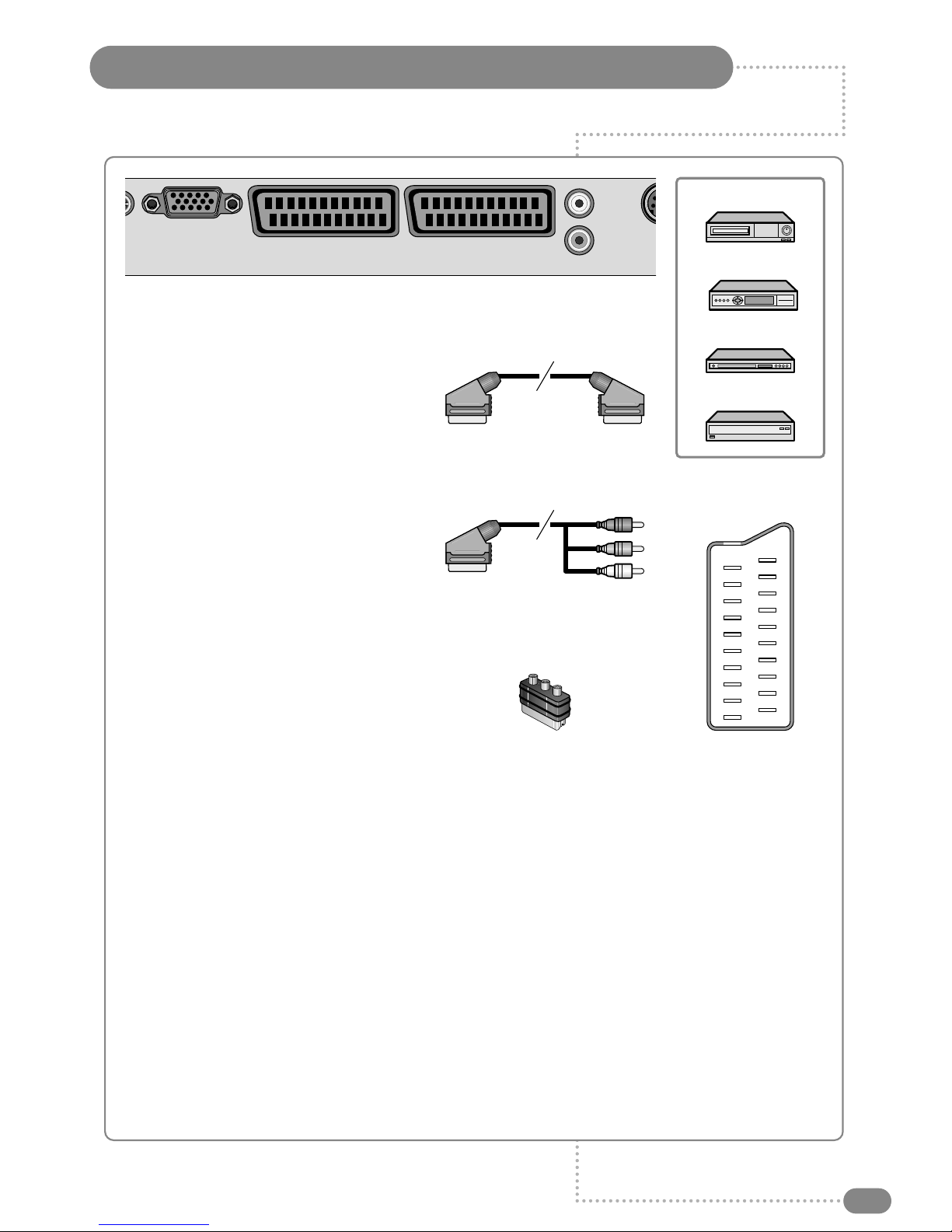
Connecting to the SCART Inputs
9
The EURO-SCART sockets can be connected to equipment with RGB or composite video inputs and
outputs. A VCR, satellite or cable receiver, DVD player, or video game console should be connected
using one of the EURO-SCART connections.
◆
The EURO-SCART 1 socket is fully connected. EURO-SCART 2 is partially (half) connected and
provides composite video and switch connection only.
◆
The outputs of the SCART sockets allow integration with a multi-room audio video system.
All custom connections should be carried out by a qualified engineer.
◆
Adaptors are commercially available to allow video and audio equipment to be connected to the
TileVision®via the EURO-SCART sockets.
See the examples in diagrams B and C.
◆
The 3.5 mm stereo Headphone socket provides a variable volume audio output which can be
connected to the auxiliary input of an audio amplifier.
◆
If the TileVision®is not being installed in a bathroom an extension lead can be connected to the
Headphone socket. The other end of the extension lead should be terminated at a surface mounted
socket of the appropriate type.
DVD Player
VCR
Video Game Console
Satellite receiver
19
17
15
13
11
9
7
5
3
1
20
18
16
14
12
10
8
6
4
2
21
EURO-SCART 1
(RGB, FB, AV –In/Out) EURO-SCART 2
(AV –In/Out)
C
d
io
S-
V
PC/Analog
(D-SUB)
L
(Mono)
Audio In
R
(A) SCART to SCART connector
(RGB Video + Audio L/R or
Composite Video + Audio L/R)
(B) SCART to RCA connectors
(Composite Video + Audio L/R)
(C) SCART to RCA adaptor
(Composite Video + Audio L/R)
SCART Pinouts
(solder side view)
SCART Connection Reference
Pin Half Name Description
1✓AOR Audio Out Right
2✓AIR Audio In Right
3✓AOL Audio Out Left + Mono
4✓AGND Audio Ground
5 N/C BGND RGB Blue Ground
6✓AIL Audio In Left + Mono
7 N/C B RGB Blue
8✓SWTCH Audio, RGB switch,16:9
9 N/C GGND RGB Green Ground
10 N/C CLKOUT Clock Out
11 N/C G RGB Green
12 N/C DATA Data Out
13 N/C RGND RGB Red Ground
14 N/C DATAGND Data Ground
15 N/C R RGB Red
16 N/C BLNK Blanking Signal
17 ✓VGND Composite Video Ground
18 N/C BLNKGND Blanking Signal Ground
19 ✓VOUT Composite Video Out
20 ✓VIN Composite Video In
21 ✓SHIELD Chassis Ground, Cable Shield
All connections must be made before sealing the front plate into the back box.

Installing the Front Plate
10
Checking back box prior to installation of front plate
Before commencing the installation of the front plate the polystyrene-blanking panel must be removed
from the back box. The next step is to ensure that the appropriate cables and their connectors are
present within the back box.
It is important to ensure that the flange inside the back box is cleaned using a grease removal agent and
allowing it to dry. The space between the back box and front plate must be even on all 4 sides. If the
flange needs to be straightened, this must be done before proceeding any further. This is very important,
as any damage will affect the unit’s waterproofing capabilities.
Installation of the front plate
Remove the front plate from its packaging and place the remote control to one side, next remove the
protective plastic film from the glass.
Introduce the lower front edge of the unit into the box and fit the earth straps to the two Earthing screws
as indicated by the green labels on the rear of the front plate. Connect all cables to their respective
sockets (refer to pages 6 to 9 of these instructions).
The next step is to remove the soft adhesive protector from the top length of special Velcro‚and press
the front plate into the back plate (it may be necessary to adjust the position of the cables to achieve a
good fit).
The unit installation must comply with all relevant electrical safety regulations before turning the mains
supply to the 24VDC power adaptor on using the remote pull switch. The unit should now show a red
indicator light showing that it is in standby mode.
The next step is to tune the unit as detailed on pages 14 to 17.
Once you are satisfied that the unit is tuned and working correctly, press the Power 0/I button to put the
unit in standby mode and isolate the unit using the remote pull switch.
Gently remove the front plate using a suction lifter; please do not use a lever to remove the front plate
as this will invalidate your guarantee. Next, remove the self-adhesive protectors from the side and
bottom Velcro strips and press the front panel into the back box with reasonable force. Take care to
apply force to all 4 sides of the box. Restore mains power to the unit using the remote pull switch and
press the Power 0/I button to turn the unit on again and check that it is still working correctly.
Sealing the unit
When you are sure that the unit is installed correctly put it in standby mode and apply a clear silicone
sealant to the joint between the sides of the back box and the sides of the front plate. Ensure that the
silicone is worked into the gap evenly and is applied without any gaps, bubbles, etc. Wipe any excess
silicone away; check visually for any gaps or bubbles and rectify if necessary. This seal is of the greatest
importance to the reliable and safe operation of this unit and must be waterproof.
Sealing Tip: To achieve a neat seal easily it is good practice to use
masking tape around the TileVision®glass screen and the surrounding
tiles, just leaving sufficient gap to apply the silicone sealant around the
joint between the sides of the back box and front plate.
Note: It is the installer’s responsibility to ensure that the TileVision®
unit is installed and sealed correctly, failure to do so will invalidate
your guarantee. The unit will require cleaning and re-sealing after any
servicing/repair operation
Cleaning Instructions
To clean the front screen, use only a soft damp cloth. Under no circumstances are abrasive
cleaners to be used, failure to observe this warning will invalidate your guarantee.
Note: A glass carrier/suction lifter is required.
Tile
Back box Grout
Velcro
Masking tape
Silicone
Screen

Remote Control
11
☛
Make sure there are no
objects between the
remote control and
its sensor.
Do not place the remote
control near a heater.
A strong blow to the
remote control may cause
it not to operate.
1
Power On/Off button
Turns the TileVision®on or off from standby
2
PSM (Picture Status Memory) button
Recalls the preferred picture setting
3
SSM (Sound Status Memory) button
Recalls the preferred sound setting
4
Mute button
Turns the sound on or off
5
Number buttons
Selects programme numbers
6
OK button
Accepts your selection or displays the current mode
7
VOL (Volume) buttons
Adjust the volume and selects/adjusts Menu Items
8
PR (Programme up/down) buttons
Selects next or previous programme or
Menu Item
9
Menu button
Displays the Main Menu
10
Teletext On/Off Teletext Mix button
See page 31 for Teletext function table
(buttons 10 to 15)
11
QV and Teletext Size button
Quick View –returns to the previously viewed programme
12
List and Teletext Index button
Displays the programme list menu
13
ARC (Aspect Ratio Control) button. Various picture
formats are available: Auto, 16:9,14:9, 4:3, 16:9 zoom,
14:9 zoom, 4:3 zoom. Press the ARC Button repeatedly
to select the desired format
Note: only 16:9 and 4:3 are available in PC mode
14
Teletext Hold button
15
TV/AV button
Selects between TV, SCART 1, SCART 2, S-VIDEO,
RADIO (only when enabled), PC Analog, and PC Digital
inputs. Clears the menu from the screen
16
Red FastText button
17
Green FastText button
18
Yellow FastText button
19
Blue FastText button
SSM
OK
MENU
PR VOL
HOLD
TEXT/MIX QV LIST
i
PSM
ARC TV
/AV
4
5
6
7
19
8
9
1 2 3
10 11 12
13 14 15
16 17 18

SSMPSM
Switching the TileVision®On/Off
Selecting a Picture from External Sources
12
1
To switch your TileVision®on, press the POWER ( ) button.
2
To switch your TileVision®off, press the POWER ( ) button
again.
After your various systems (audio and video) have been connected, you can view any of the
sources by selecting the appropriate external input.
1
Make sure all the necessary connections have been made.
2
Press the POWER ( ) button to switch the device on.
3
Press the TV/AV button to select required external input
mode –Antenna (TV), SCART 1, SCART 2, S-VIDEO,
RADIO (when enabled), PC Analog, and PC Digital inputs.
The input is shown at the top right corner of the screen.
1
Press the MENU ( ) button.
2
Press the PR
UD
buttons to select the Setup menu and then
press the VOL
R
button.
3
Press the PR
UD
buttons to select the Language menu and
then press the VOL
R
button.
4
Press the PR
UD
buttons to select your desired language and
then press the VOL
R
button.
5
Press the TV/AV button.
All the on-screen displays will now appear in the selected
language.
MENU
HOLD
ARC TV
/AV
Selecting your On-screen Language
When you start using your TV for the first time, you must select the language in which to
display all on-screen menus.
Setup
Auto programme
Manual programme
Programme edit
Language
Language
English
Deutsch
Français
Español
Italiano
Nederlands
Português
☛
The content of the Language menu is region
dependent and may include different languages to
those shown here.
Picture
Contrast 90
Brightness 75
Colour 75
Sharpness 60
Sound
Equalizer
Balance 0
AVL Off
Surround Off
Sound Mode MONO
Special
Clock
Blue Back Off
Auto Sleep Off
Child Lock Off
Radio Off
ARC 16:9
Setup
Auto programme
Manual programme
Programme edit
Language
Equalizer
Flat
Music
Movie
Speech
User 0.1 0.5 1.5 5.0 10Khz
Auto Programme
System BG
Start
Manual Programme
Programme 1
Channel 69
Table V/UHF
System BG
Search
Memorize
Name -----
Main menu
Picture
Sound
Special
Setup
Clock
Clock --:--
Off Time --:-- Off
On Time --:-- Off
On Programme 1
Programme Edit
P00----- P05-----
P01----- P06-----
P02----- P07-----
P03----- P08-----
P04----- P09-----
■Delete ■Name
■Move ■Skip
On-screen Menus and Displays
13
SSM
OK
MENU
PR VOL
HOLD
TEXT/MIX QV LIST
i
PSM
ARC TV
/AV
1
Press the MENU button to display the main menu.
2
Press the PR
UD
buttons to select menus.
3
Press VOL
LR
buttons to adjust menu items.
4
Press MENU to go back to the previous menu.
5
Press TV/AV to exit the menus and confirm settings.
Tuning, Setup and Editing TV Programmes
14
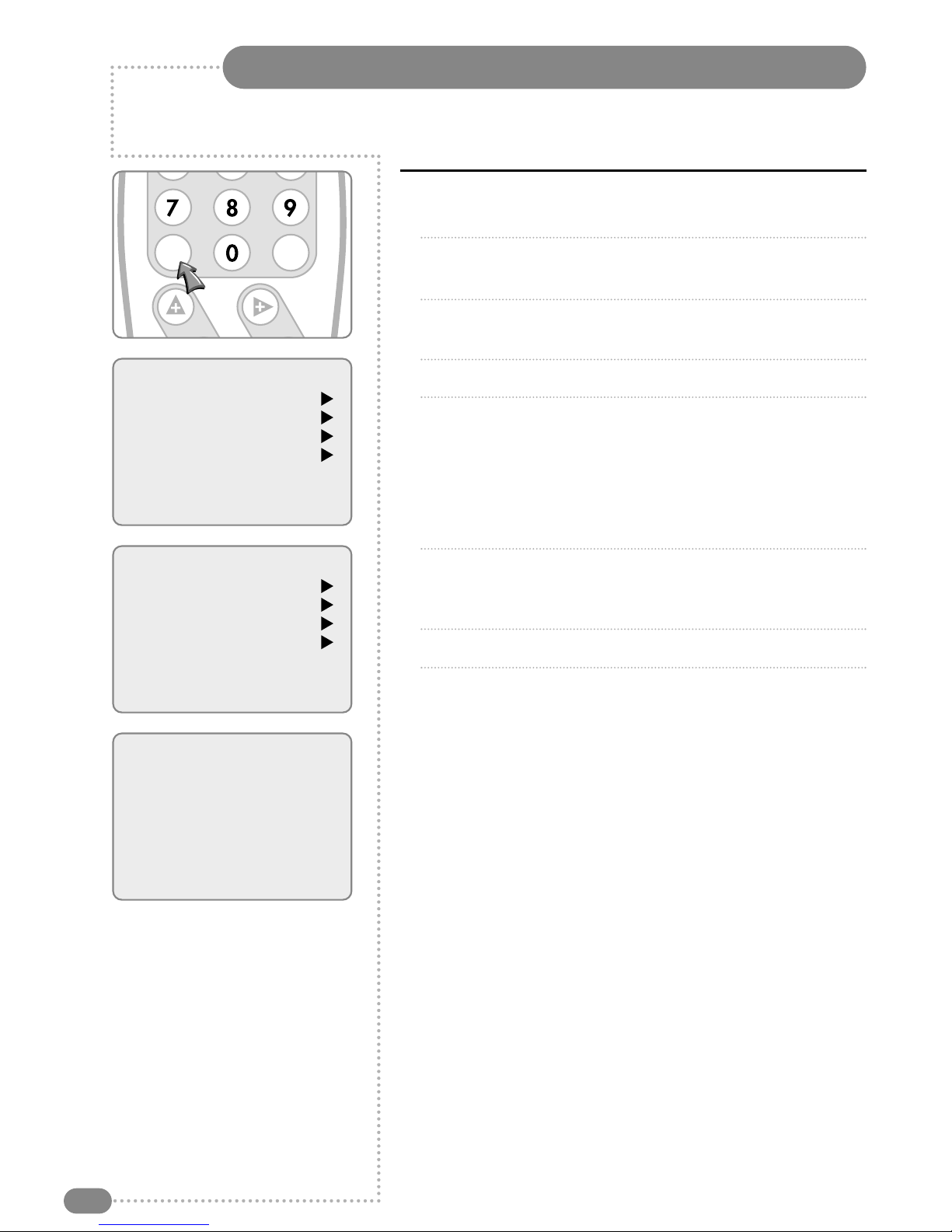
Auto Programme
1
Press the MENU button.
2
Press the PR
UD
buttons to select the SETUP menu and then
press the VOL
R
button.
3
Press the PR
UD
buttons to select the Auto Programme menu
and then press the VOL
R
button.
4
Press the PR
UD
buttons to select System.
5
Select a TV system with the VOL
LR
buttons:
BG: Germany/Asia/M.East/Africa/Australia
I: UK/Hong Kong/South Africa
DK: CIS/China/East Europe
L: France.
6
Press the PR
UD
buttons to select Start and press the VOL
R
button to confirm. The Auto Programme will now start, this will
take a few minutes to complete.
7
Press the TV/AV button to return to normal TV viewing.
To delete, skip, move or name the stored programmes see
Programme Edit, on page 16.
OK
MENU
PR VOL
Main menu
Picture
Sound
Special
Setup
Setup
Auto programme
Manual programme
Programme edit
Language
Auto Programme
System BG
Start
Note: It is recommended that Auto Programme is used when installing TileVision®as all
available programmes will be stored.
Tuning, Setup and Editing TV Programmes
15
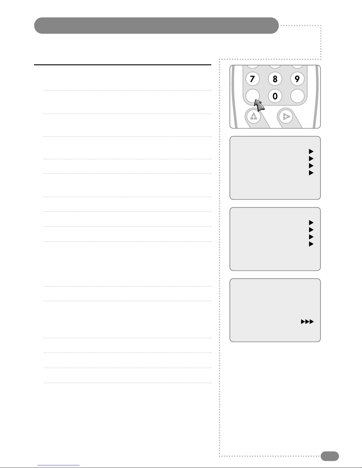
Manual Programme
01
Press the MENU button.
02
Press the PR
UD
buttons to select the SETUP menu and then
press the VOL
R
button.
03
Press the PR
UD
buttons to select the Manual Programme
menu and then press the VOL
R
button.
04
Select a programme with the VOL
LR
buttons or number
buttons.
05
Press the PR
UD
buttons to select Channel menu.
06
Press the VOL
R
button to select a channel, or enter a channel
directly with the number buttons.
07
Press the PR
UD
buttons to select the Table menu.
08
Press the VOL
R
button to select V/UHF or Cable as required.
09
Select a TV system with the VOL
LR
buttons:
BG: Germany/Asia/M.East/Africa/Australia
I: UK/Hong Kong/South Africa
DK: CIS/China/East Europe
L: France.
10
Press the PR
UD
buttons to select Search menu.
When you press the VOL
LR
buttons, the TileVision changes
programmes in sequence. You will see all the programmes that
the TileVision has memorised. You will not see programmes that
were either erased or not memorised.
11
Press the PR
UD
buttons to select the Memorize menu.
12
Press the VOL
R
button to store it.
13
Press the Menu button to return to the previous menu.
14
Press the TV/AV button to return to normal TV viewing.
Main menu
Picture
Sound
Special
Setup
Setup
Auto programme
Manual programme
Programme edit
Language
Manual Programme
Programme 1
Channel 69
Table V/UHF
System BG
Search
Memorize
Name -----
Manual Programme lets you tune and arrange the programmes in whatever order you desire.
You can also assign a programme name with 5 characters for each programme number.
OK
MENU
PR VOL

Tuning, Setup and Editing TV Programmes
16
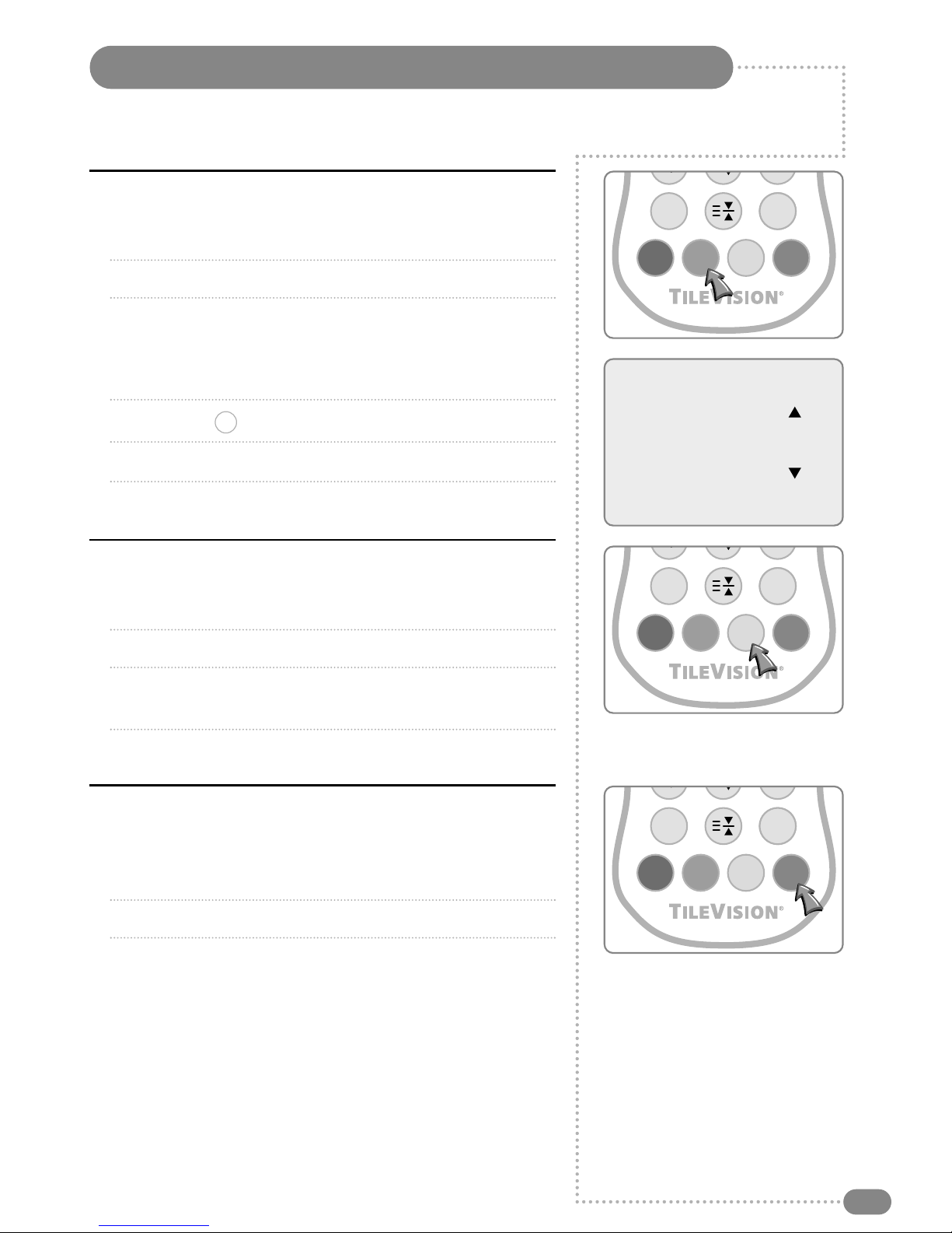
Programme Edit
This function enables you to delete or skip the stored programmes.
You can also move channels to different programme numbers, or
insert blank programme data into the selected programme number.
1
Press the MENU button.
2
Press the PR
UD
buttons to select the SETUP menu and then
press the VOL
R
button.
3
Press the PR
UD
buttons to select Programme Edit and then
press the VOL
R
button.
4
Select the programme name to edit with the PR
UD
buttons and
PR
UD
buttons.
Deleting a programme
1
Select a programme to be deleted with the PR
UD
or
VOL
LR
buttons.
2
Press the RED button once. The selected programme is deleted,
all the following programmes shift up one position.
Main menu
Picture
Sound
Special
Setup
Setup
Auto programme
Manual programme
Programme edit
Language
Programme Edit
P00----- P05-----
P01----- P06-----
P02----- P07-----
P03----- P08-----
P04----- P09-----
■Delete ■Name
■Move ■Skip
OK
MENU
PR VOL
HOLD
ARC TV
/AV
Tuning, Setup and Editing TV Programmes
17
Naming a programme in Programme Edit menu
1
Select a programme to be named with the PR
UD
or
VOL
LR
buttons.
2
Press the GREEN button.
3
Press the PR
UD
buttons repeatedly to select letters
(A to z –Capitals and small), numbers (0 to 9), blank or –.
Press the VOL
LR
buttons to select the position of the
character (1 to 5) in the programme name.
4
Press the OK ( ) button to store it.
5
Press the MENU button to return to the previous menu.
6
Press the TV/AV button to return to normal TV viewing.
Moving a programme in Programme Edit menu
1
Select a programme to be moved with the PR
UD
or
VOL
LR
buttons.
2
Press the YELLOW button.
3
Move the programme to the desired programme number with the
PR
UD
or VOL
LR
buttons.
4
Press the YELLOW button again to release this function.
Skipping a programme number in Programme
Edit menu
1
Select a programme to be skipped with the PR
UD
or
VOL
LR
buttons.
2
Press the BLUE button. The skipped programme turns blue.
3
Press the BLUE button again to release the skipped programme.
OK
Edit Name
Station P01 -----
HOLD
ARC TV
/AV
HOLD
ARC TV
/AV
HOLD
ARC TV
/AV
☛
When a programme number is skipped you will not
be able to select the programme using the PR UD
button during normal TV viewing.
If you want to select a skipped programme,
enter the programme number with the
NUMBER buttons or select it in the
Programme Edit menu.

Picture Control
18
Manual Picture Control
1
Press the MENU button.
2
Press the PR
UD
buttons to select the Picture menu and then
press the VOL
R
button.
3
Press the PR
UD
buttons to select a picture item.
4
Press the VOL
LR
buttons to adjust the picture setting to your
requirement.
5
Press the TV/AV button to store your personal preferences
in User.
Auto Picture Control
The Picture options –Dynamic, Standard, Mild, and Game are
programmed for optimum picture reproduction at the factory and
cannot be changed.
PSM (Picture Status Memory)
1 Press the PSM ( ) button.
2
Press the button repeatedly. Each press of the button changes
the screen display as below:
Dynamic Standard Mild Game User
●
Dynamic: Vivid Picture.
●
Standard: Standard Picture.
●
Mild: Softer Picture.
●
Game: External Video Game Picture Setup.
●
User: Manual Picture Setup.
3
Press the ( ) button.
OK
PSM
Main menu
Picture
Sound
Special
Setup
Picture
Contrast 90
Brightness 75
Colour 75
Sharpness 60
You can adjust picture Contrast, Brightness, Colour and Sharpness to the levels you prefer.
Selected Item Setting Change
Contrast Less Contrast VOL
L
0–100
R
VOL More Contrast
Brightness Darker VOL
L
0–100
R
VOL Brighter
Colour Lower Colour Intensity VOL
L
0–100
R
VOL Higher Colour Intensity
Sharpness Soft picture VOL
L
0–100
R
VOL Sharp Picture
SSMPSM
☛
In PC mode, the PSM
function is not
available.
Table of contents
Other TileVision TV manuals

TileVision
TileVision TV/104/FR2 User manual

TileVision
TileVision 17" User manual

TileVision
TileVision TV/17/FR2 User manual

TileVision
TileVision 22" User manual

TileVision
TileVision 22" mirror finish User manual

TileVision
TileVision TV/17/FR5/PS User manual

TileVision
TileVision TV/17/FR4/PS User manual

TileVision
TileVision TV/19/FR1 User manual

TileVision
TileVision TV/17/FR User manual

TileVision
TileVision TV/17/FR3/PS User manual


