TILLIG BAHN 85640 User manual

Güterwagen
www.tillig.com / www.facebook.com/tilligbahn
Bausatz H0m/e-Weiche
Kit H0m/e-Points •Kit de construction H0m/e-Aiguillage •Sada H0m/e-Výhybka •Zestaw H0m/e-Zwrotnica
– 1 –
Art.-Nr. / Item no. /
Réf. / Art.-č. / Nr art.: 85640
(DE) H0m-Weiche, W1 18°, EW/ IBW, re./li.
(GB) H0m-Points, W1 18°, EW / IBW, right/left
(FR) H0m-Aiguillage, W1 18°, EW / IBW,
droite/gauche
(CZ) H0m-Výhybka, W1 18°, EW / IBW, pravá/levá
(PL) H0m-Zwrotnica, W1 18°, EW / IBW,
prawa/lewa
Achtung! Die hohe Flexibilität des Schwel-lengitters bedingt erhöhte Anforderungen bei der Weichenmontage. Dem Bausatz liegen 2 Paar vorgefertigte Endschienen bei (1 Satz für rechte; 1 Satz für linke Weichen). Die Herz-stückspitze wird dabei jeweils durch die Endschiene des Stammgleises (3) gebildet. Die vorliegende Bauanleitung gilt als Orientie-rung, individuelle Erfahrungen ermöglichen andere technologische Abläufe bei der Weichenmontage.368230-S.104.06.2015Grundelement: symmetr. Außenbogenweiche H0m H0eHerzstückwinkel: 14° 14°Radius (mm): 810/810 675/675
12121122111313883101055996744
1. Grundform: Symmetr. Außenbogenweiche(Streckung möglich)2. Einfache Weiche: R (mm) entsprechend Streckung3. Bogenweichen: 360...490 300...410nach BedarfNicht geeignet für Kinder unter 3 Jahren wegen abnehmbarer und verschluckbarer Kleinteile und Verletzungsgefahr durch funktionsbedingte scharfe Ecken und Kanten. 0-3
Dieses Produkt darf am Ende seiner Nutzungsdauer nicht über den normalen Hausmüll entsorgt werden, sondernmuss an einem Sammelpunkt für das Recycling von elektrischenund elektronischen Geräten abgegeben werden.Bitte fragen Sie bei Ihrem Händler oder der Gemeindeverwaltungnach der zuständigen Entsorgungsstelle.
Art.-Nr. 85640H0m-WeicheW1 18°; EW/IBW re/liArt.-Nr. 85641H0e-WeicheW1 18°; EW/IBW re/liAchtung! Die hohe Flexibilität des Schwel-lengitters bedingt erhöhte Anforderungen bei der Weichenmontage. Dem Bausatz liegen 2 Paar vorgefertigte Endschienen bei (1 Satz für rechte; 1 Satz für linke Weichen). Die Herz-stückspitze wird dabei jeweils durch die Endschiene des Stammgleises (3) gebildet. Die vorliegende Bauanleitung gilt als Orientie-rung, individuelle Erfahrungen ermöglichen andere technologische Abläufe bei der Weichenmontage.368230-S.104.06.2015Grundelement: symmetr. Außenbogenweiche H0m H0eHerzstückwinkel: 14° 14°Radius (mm): 810/810 675/675121211221113138831010559967441. Grundform: Symmetr. Außenbogenweiche(Streckung möglich)2. Einfache Weiche: R (mm) entsprechend Streckung3. Bogenweichen: 360...490 300...410nach Bedarf
Art.-Nr. 85640H0m-WeicheW1 18°; EW/IBW re/liArt.-Nr. 85641H0e-WeicheW1 18°; EW/IBW re/liNicht geeignet für Kinder unter 3 Jahren wegen abnehmbarer und verschluckbarer Kleinteile und Verletzungsgefahr durch funktionsbedingte scharfe Ecken und Kanten. 0-3
TILLIG Modellbahnen GmbH
Promenade 1, 01855 SebnitzTel.: +49 (0)35971 903-45, www.tillig.com
Dieses Produkt darf am Ende seiner Nutzungsdauer nicht über den normalen Hausmüll entsorgt werden, sondernmuss an einem Sammelpunkt für das Recycling von elektrischenund elektronischen Geräten abgegeben werden.Bitte fragen Sie bei Ihrem Händler oder der Gemeindeverwaltungnach der zuständigen Entsorgungsstelle.
Tech nisc he Änderun gen vorbeha lten !
Bei Reklamationen wenden Sie sich bitte an Ihren Fachhändler.
TILLIG Modellbahnen GmbH
Promenade 1, 01855 SebnitzTel.: +49 (0)35971 903-45, www.tillig.com
Tech nisc he Änd erungen vorbe halt en!
Bei Reklamationen wenden Sie sich bitte an Ihren Fachhändler.
(DE) Bitte vergleichen Sie vor dem
Montagebeginn die vorhandenen
Teile mit der Bauanleitung. Rekla-
mationen montierter oder teilmon-
tierter Bausätze können nicht aner-
kannt werden!
(GB) Before starting to assemble, please
check that all parts are there by com-
paring them with the building instruc-
tions. Complaints about assembled
or partially assembled kits cannot be
accepted!
(FR) Avant de commencer le montage, com-
parer les pièces disponibles avec celles
gurant dans les instructions de service.
Nous ne pouvons pas accepter les réclama-
tions concernant des kits montés ou parti-
ellement montés.
(CZ) Porovnejte prosím před montáží dané
součástky s návodem. Reklamace smonto-
vaných či částečně smontovaných dílů ne-
bude brána v potaz!
(PL) Przed rozpoczęciem montażu należy
porównać otrzymane części z instrukcją
montażu. Reklamacje złożonych lub częś-
ciowo złożonych zestawów nie będą uzna-
wane!
Art.-Nr. / Item no. /
Réf. / Art.-č. / Nr art.: 85641
(DE) H0e-Weiche, W1 18°, EW/ IBW, re./li.
(GB) H0e-Points, W1 18°, EW / IBW, right/left
(FR) H0e-Aiguillage, W1 18°, EW / IBW,
droite/gauche
(CZ) H0e-Výhybka, W1 18°, EW / IBW, pravá/levá
(PL) H0e-Zwrotnica, W1 18°, EW / IBW,
prawa/lewa
GEOMETRIE
Grundelement: Symmetr. Außenbogenweiche
Herzstückwinkel: H0m/H0e: 14°
Radius (mm): H0m: 810/810 - H0e: 675/675
1. Um eine exakte Bearbeitung der Prole für die ge-
wünschte Weichengeometrie zu ermöglichen, fertigt
man sich vor Beginn eine Schablone des Weichen-
grundrisses an.
2. Enfernen von Fräsrückständen/Graten an den Prolen.
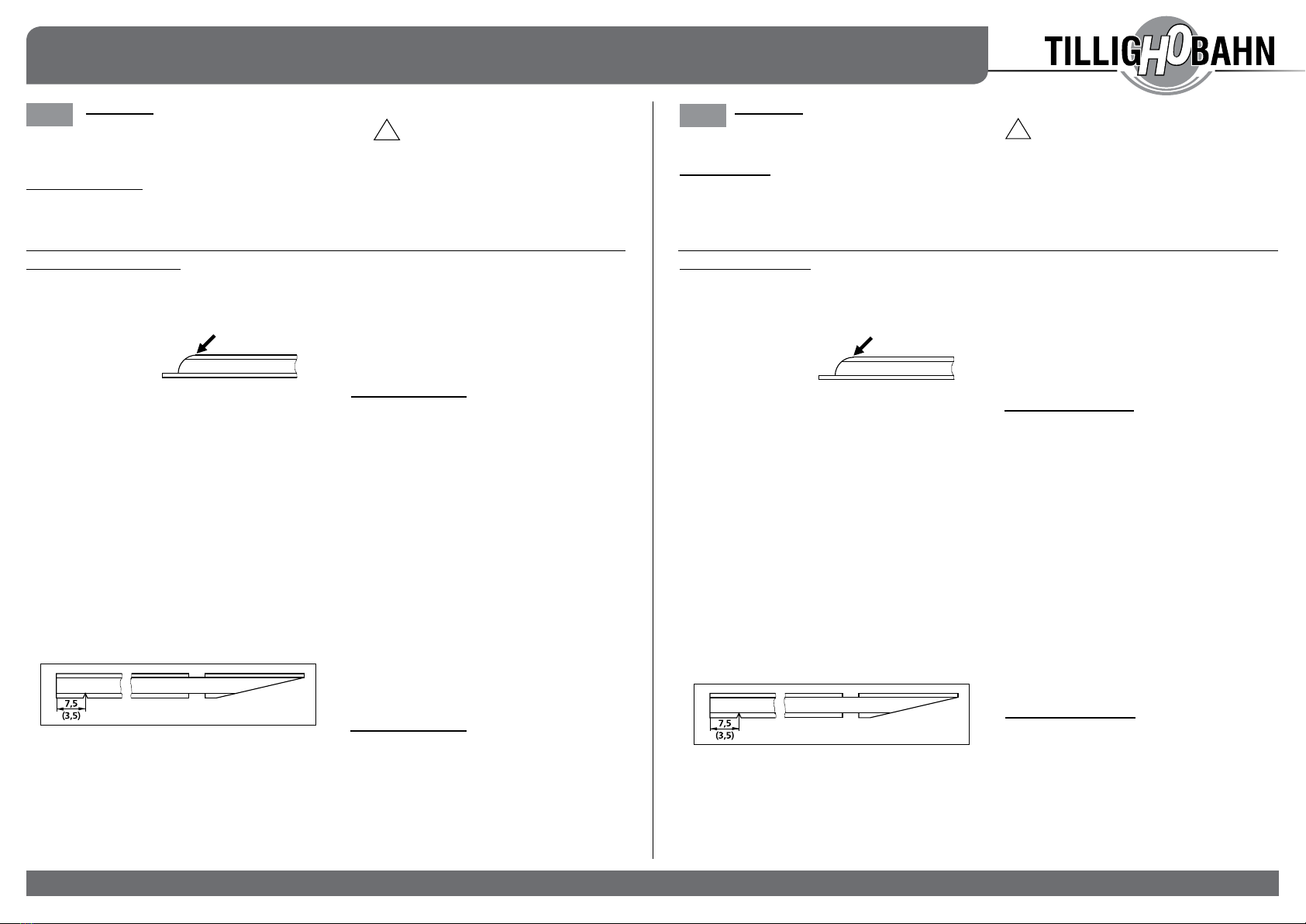
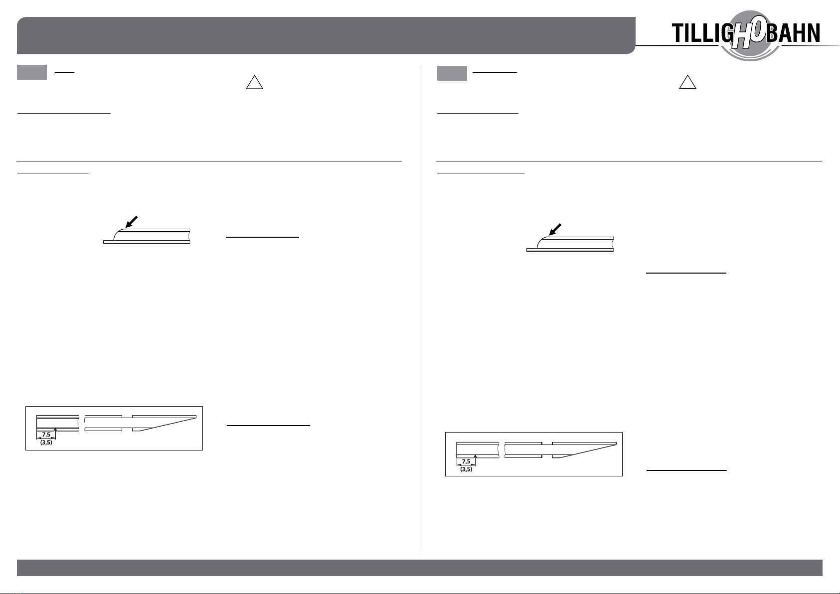
3. An den Zungenspitzen (2) leichte Radien anbringen.
4. Blanken der Schienenfüße an den für Stromversorgung
vorgesehenen Stellen. Durch gründliche Entfernung
der Brünierung lässt sich das Neusilberprol problem-
los mit Stromleitern löten.
5. Ablängen der Prole entsprechend der gewünschten
Geometrie. Die Zungen-Mittelschienen (2/10) auf die
Schablone legen, entsprechenden Radius verbiegen.
Die Zungenspitze (2) in der Mitte des Stellfaches (6) an-
legen, den Überstand vom Ende der Mittelschiene (10)
bis zur Kunststoügelschiene (5) mittels Seitenschnei-
der entfernen, Schnittstelle mit Feile säubern. Einbrin-
gen der Kerben in Mittelschienen (s. Punkt 5). Die Herz-
stückspitze (durch die Endschiene des Stammgleises
(3) auf 7,8 mm (H0m) bzw. 7,0 mm (H0e) Abstand zum
Abknickpunkt, Kerbe, (4)) ausrichten. Die Endschiene
des Zweiggleises (11) liegt mit der Spitze am Ende der
Phase der Herzstückspitze (7).
6. 7,5 mm (H0m) bzw. 3,5 mm (H0e) vom Ende der
Mittelschiene (10) im Fuß eine Kerbe einbringen.
7. Die Aussparung (8) im Fußbereich an den Außenschie-
nen (1) liegt innen am Weichenausgang und garantiert
das saubere Anliegen der Zungen.
Außenschienen (1) die Aussparung (8) selbst mit
Feile einbringen!
8. Die beiden mitgelieferten Strombrücken bei Bedarf: die
Enden durch die beiden Kleineisen der Mittelschiene
unterhalb der Kunststoügelschienen und der End-
schienenkleineisen oberhalb der Kunststoügelschiene
(12/13) von der Weichenrückseite durchstecken und in
den Kleineisen in Einschubrichtung der Prole umbie-
gen. Die Schienenverbinder vor der Montage auf die
Prole aufstecken (Iso-Verbinder auf Endschienen).
9. Montagevariante 1:
MONTAGEANLEITUNG:
Achtung! Die hohe Flexibilität des Schwellen-
gitters bedingt erhöhte Anforderungen bei der
Weichenmontage. Dem Bausatz liegen 2 Paar vorge-
fertigte Endschienen bei (1 Satz für rechte; 1 Satz für
linke Weichen). Die Herzstückspitze wird dabei jeweils
durch die Endschiene des Stammgleises (3) gebildet.
Die vorliegende Bauanleitung gilt als Orientierung, in-
dividuelle Erfahrungen ermöglichen andere technolo-
gische Abläufe bei der Weichenmontage.
Erwärmen des Schwellengitters mittels Heißluftdüse,
konzentriert auf die Wellstege zwischen den Schwellen.
Achtung! Zu lange und intensive Erwärmung
So wie sich die Wellstege leicht dehnen (stauchen) las-
sen, das Schwellengitter mittels Kleber (z. B. Loctite 496)
auf der Anlage befestigen. Die Fixierung des Gitters er-
folgt durch Abkühlung im befestigten Zustand.
Anschließend erfolgt das Einschieben der Prole.
Außenschienen Endschienen
Zungen-Mittelschienen.
-
gessen!
Das Umbiegen der Zungenhaken im Stellfach (6) erfolgt
seitlich mit einer Pinzette. Die Zungenspitzen anschlie-
ßend leicht anheben und Stellschwelle einschieben.
Zungenhaken in Langlöcher einhängen. Danach die
Kunststoradlenker (9) in die Kleineisen einschieben.
Montagevariante 2:
Die Schablone o. Anriss der gewünschten Weichengeo-
metrie auf eine Sperrholzplatte aufbringen. Schwellen-
rost erwärmen (vom Weichenausgang beginnend), die
fertig gebogenen Bereiche mittels Stahlstiften um die
Schwellen xieren.
Diese Schritte fortführen bis zum Weicheneingang.
Anschließend Prole einbringen nach Variante 1. Nach
Abnehmen der Weiche vom Unterbau lässt sich deren
Lage bis zum Anbringen auf der Anlage korrigieren.
!
BAUVARIANTEN
1. Symmetr. Außenbogenweiche (Streckung möglich)
2. R (mm) entsprechend Streckung
3. Bogenweichen: H0m: 360...490 / H0e: 300...490 nach Bedarf
DE
368230 / 22.06.2020
Güterwagen
www.tillig.com / www.facebook.com/tilligbahn 368230 / 22.06.2020
GÉOMÉTRIE
Élément de base: Aiguillage californien symétrique
Angle de cœur: H0m/H0e: 14°
Rayon (mm): H0m: 810/810 - H0e: 675/675
1. Fabriquez un gabarit du plan des aiguillages au
préalable an de permettre un traitement précis des
prolés pour la géométrie d‘aiguillage souhaitée.
2. Retirez les résidus de fraisage / d’ébavurage sur les
prolés.
3. Appliquer de légers
rayons sur la pointe
des lames (2).
4. Lustrer les patins de rail sur les points prévus pour
l’alimentation électrique. Le retrait ecace du brunis-
sage permet de souder sans problème le nouveau
prolé en maillechort avec les conducteurs élec-
triques.
5. Coupe des prolés en fonction de la géométrie dé-
sirée. Poser les lames d’aiguille centrales (2/10)
sur le gabarit, plier le rayon correspondant. Poser
la pointe d’aiguille (2) au centre du compartiment
(6), retirer le surnageant à partir de l‘extrémité du
rail central (10) jusqu’au contre-rail en plastique
(5) à l’aide d’une pince coupante, épurer l’interface
avec une lime. Introduction d’encoches dans les rails
centraux (cf. Point 5) Disposer la pointe du cœur (à
travers le rail d’extrémité de la voie principale (3) à
une distance de 7,8 mm (H0m) ou 7,0 mm (H0e) du
point de pliage, c’est-à-dire l’encoche (4). La pointe
du rail d’extrémité de la voie déviée (11) se situe à
l’extrémité de la phase de la pointe du cœur (7).
6. Installer une encoche à 7,5 mm (H0m) ou 3,5 mm
(H0e) de l’extrémité du rail central (10), dans le patin.
7. L’encoche (8) au niveau du patin sur les rails extéri-
eurs (1) se trouve à la sortie de l’aiguillage et ga-
rantit ainsi une pose propre des lames d’aiguille.
vous-même avec une lime!
8. Les deux dérivations électriques fournies: si néces-
saire, pousser les extrémités à travers les deux
éléments de xation du rail central sous les cont-
re-rails en plastique et les éléments de xation d‘ex-
trémité au-dessus du contre-rail en plastique (12/13)
depuis la face arrière des aiguillages et les plier dans
les éléments de xation de la voie dans la direction
d‘insertion des prolés. Installer les connecteurs de
rail sur les prolés avant le montage (connecteur Iso
sur rails d’extrémité).
9. Variante de montage 1:
MANUEL DE MONTAGE:
Attention! La grande exibilité du caillebotis de tra-
verse est responsable des plus hautes exigences
lors du montage des aiguillages. Le kit de construction
est fourni avec 2 paires de rails d’extrémité préfabriqués
(1 lot pour l’aiguillage de droite, 1 lot pour l’aiguillage de
gauche). Ce faisant, la pointe de cœur est formée par
les rails d’extrémité de la voie complète (3). Le présent
manuel fait oce d’orientation, les expériences individu-
elles permettent de procéder autrement au montage des
aiguillages.
Chaue de la grille de traverser à l’aide d’une buse à
air chaud, concentrée sur les bandes ondulées entre
les traverses.
Puisque les bandes ondulées s’étirent légèrement
(elles remontent), xer la grille de traverses sur l’in-
stallation avec de la colle (par ex. Loctite 496). La
xation de la grille est réalisée par le refroidissement
à l’état solide. Pour nir, insérer les prolés.
Ordre: Rails extérieurs rails d’extrémité
lames d’aiguille rail central
Attention! Ne pas oublier le pliage préalable pré-
Le pliage du crochet dans le compartiment (6) s’ef-
fectue sur le côté avec une pincette. Soulever ensuite
légèrement les pointes des lames d’aiguille et insé-
rer la traverse glissière. Accrocher les crochets dans
les trous oblongs. Insérer ensuite le rail de guidage
(9) dans les éléments de xation de la voie
Variante de montage 2:
Appliquer le gabarit ou le tracé de la géométrie
souhaitée des aiguillages sur un panneau en cont-
replaqué. Réchauer la grille de traverse (en com-
mençant par la sortie de l’aiguillage), xer les zo-
nes pré-pliées autour des traverses à l’aide de tiges
en acier. Continuer les étapes jusqu’au début de
l’aiguillage. Installer ensuite les prolés conformé-
ment à la variante 1. Après avoir retiré l‘aiguillage de
la sous-construction, sa position peut être corrigée
jusqu‘à ce qu‘il soit monté sur le système.
BAUVARIANTEN
1. Forme basique: Aiguillage californien symétrique
(étirement possible)
2. Aiguillage simple: R (mm) allongement correspondant
3. Aiguillages en courbe: H0m: 360...490 / H0e: 300...490
en fonction des besoins
!
– 2 –
GEOMETRY
Basic element: Symmetrical outer curve switch
Frog angle: H0m/H0e: 14°
Radius (mm): H0m: 810/810 - H0e: 675/675
1. Symmetrical outer curve switch (extension possible)
2. R (mm) in accordance with extension
3. Curved turnouts: H0m: 360...490 / H0e: 300...490 as required
FR
GB Caution! The high exibility of the sleeper grid
results in increased requirements when the
turnout installation is concerned. The kit includes 2
pairs of prefabricated end rails (1 set for right; 1 set
for left turnouts). The frog tip is formed by the end
rail of the main track (3). This construction manual is
intended as an guide, individual experiences enable
other technological processes during the turnout in-
stallation.
!
1. A template of the turnout ground plan is produced
before starting in order to facilitate an exact proces-
sing of the sections for the desired turnout geometry.
2. Removal of milling residues/burrs on the sections.
3. Attach slight radii to
the tips of the switch
(2).
4. Polishing the rail feet at the points provided for po-
wer supply. The nickel silver section can be simply
soldered to conductors by thoroughly removing the
burnishing.
5. Cutting the sections to length according to the desi-
red geometry. Place the switch centre rails (2/10) on
the template, bend the corresponding radius. Place
the tip of the switch (2) in the middle of the setting
compartment (6), remove the projection from the end
of the middle rail (10) extending to the plastic wing
rail (5) using side cutters, clean the interface with a
le. Insert the notches in the middle rails (see point
5). Align the frog tip (through the end rail of the main
track (3) to 7.8 mm (H0m) or 7.0 mm (H0e) distance
from the turn-o point, notch, (4)). The end rail of the
branch track (11) has its tip at the end of the phase
of the frog tip (7).
6. Insert a notch 7.5 mm (H0m) or 3.5 mm (H0e) from
the end of the middle rail (10) in the foot.
7. The recess (8) in the foot area on the outer rails
(1) is located on the inside of the turnout exit
and guarantees a clean contact of the switches.
8. The two current bridges that come with the delivery
if required: Push the ends through the two track
fastening of the centre rail below the plastic wing
rails and the end rail track fastenings above the
plastic wing rail (12/13) from the back of the switch
and bend them over in the track fastenings in the
direction of insertion of the sections. Push the rail
connectors onto the sections before installation
(Iso-connectors on end rails).
9. Installation option 1:
Heating up of the sleeper grid by means of a hot air
nozzle, concentrated on the corrugated webs bet-
ween the sleepers.
Caution! Heating over too long a period or which
-
pers!
The sleeper grid can also be fastened to the system
with adhesive (e.g. Loctite 496) in just the same way
that the corrugated webs can be easily stretched
(compressed). The grid is xed by means of cooling
in its attached state. The sections are then inserted.
Outer rails end rails
switch middle rails.
the sections!
The switch hooks in the storage compartment (6)
are bent using tweezers. Then slightly lift the tips of
the switch and insert the setting threshold. Hook the
switch hook into slotted holes. Then push the plastic
handlebars (9) into the track fastenings.
Installation option 2:
Apply the template or outline of the desired turnout
geometry to a plywood plate. Heat the sleeper grate
(starting from the turnout exit), x the nished curved
areas around the sleepers using steel pins. Continue
these steps until you reach the turnout entrance.
Then insert the sections according to version 1. After
removing the turnout from the substructure, its posi-
tion can be corrected until it is mounted on the set.
Bausatz H0m/e-Weiche
Kit H0m/e-Points •Kit de construction H0m/e-Aiguillage •Sada H0m/e-Výhybka •Zestaw H0m/e-Zwrotnica
Güterwagen
www.tillig.com / www.facebook.com/tilligbahn
GEOMETRIA
Element podstawowy: symetr. rozjazd łukowy dwustronny
H0m/H0e: 14°
H0m: 810/810 - H0e: 675/675
1. W celu umożliwienia dokładnej obróbki proli dla
pożądanej geometrii zwrotnicy, należy przed roz-
poczęciem sporządzić sobie szablon rzutu poziome-
go zwrotnicy.
2. Usunąć z proli pozostałości frezowania/zadziory.
3. Na szczytach iglic (2)
nanieść lekkie pro-
mienie.
4. Wybłyszczyć stopki
szyn w miejscach przewidzianych dla zasilania ener-
gią elektryczną. Przez dokładne usunięcie oksydo-
wania, prol z mosiądzu wysokoniklowego można
bez problemu przylutować do przewodnika prądu.
5. Prole przyciąć odpowiednio do pożądanej geome-
trii. Położyć iglicowe szyny środkowe (2/10) na sz-
ablonie, wygiąć odpowiedni promień. Ułożyć ostrze
iglicy (2) w środku przegródki nastawczej (6), usunąć
nadmiar od końca szyny środkowej (10) aż do szyny
skrzydłowej z tworzywa sztucznego (5) za pomocą
szczypiec do cięcia drutu, miejsce cięcia oczyścić
pilnikiem. Naciąć karby na szynach środkowych (p.
punkt 5). Ustawić wierzchołek krzyżownicy (przez
szynę końcową toru zasadniczego (3) w odległości
7,8 mm (H0m) wzgl. 7,0 mm (H0e) od punktu zgię-
cia, (4)). Szyna końcowa toru zwrotnego (11) leży
ostrzem na końcu fazy wierzchołka krzyżownicy (7).
6. Naciąć karb 7,5 mm (H0m) wzgl. 3,5 mm (H0e) od
końca szyny środkowej (10) na stopce.
7. Wgłębienie (8) w okolicy stopki w szynach zewnętrz-
nych (1) leży wewnątrz na wyjściu zwrotnicy i gwa-
rantuje dokładne przyłożenie iglic.
8. W razie potrzeby zastosowania obu załączonych
mostków prądowych: przełożyć końce przez obie
złączki szyny środkowej poniżej szyn skrzydłowych
z tworzywa sztucznego i złączek szyn końcowych
powyżej szyny skrzydłowej z tworzywa sztucznego
(12/13) od strony tylnej zwrotnicy i wgiąć do złąc-
zek w kierunku wkładania proli. Przed montażem
wsunąć łączniki szynowe na prol (złączki ISO na
szynach końcowych).
9.
Uwaga! Wysoka elastyczność kraty
podkładowej warunkuje zwiększone
wymagania przy montażu zwrotnicy. Zestaw
zawiera 2 pary prefabrykowanych szyn koń-
cowych (1 para dla prawej, 1 dla lewej zwrot-
nicy). Wierzchołek krzyżownicy tworzy przy
tym dana szyna końcowa toru zasadniczego
(3). Załączona instrukcja montażu służy do ori-
entacji, indywidualne doświadczenie umożliwi
inny przebieg montażu zwrotnicy.
Rozgrzać kratę podkładową za pomocą dyszy z
gorącym powietrzem, skoncentrowanej na mostki
faliste między podkładami.
-
Tak jak można, mostki faliste lekko rozciągnąć (zg-
nieść) i umocować kratę podkładową za pomocą
kleju (np. Loctite 496) do instalacji. Unieruchomienie
kraty następuje przez ostygnięcie w stanie umoco-
wanym. Następnie należy wsunąć prole.
Szyny zewnętrzne szyny końcowe
iglicowe szyny środkowe.
Przegięcie haków iglic w przegródce nastawczej (6)
należy wykonać z boku za pomocą pęsety. Następ-
nie szczyty iglic lekko podnieść i wsunąć podkład
nastawczy. Zawiesić haki iglic w otworach podłuż-
nych. Następnie wsunąć kierownicę z tworzywa sz-
tucznego (9) w złączki.
Nanieść szablon lub zarysy pożądanej geomet-
rii zwrotnicy na arkusz sklejki. Ogrzać kratę pod-
kładową (zaczynając od wyjścia zwrotnicy), za-
mocować już wygięte odcinki za pomocą kołków
stalowych wokół podkładów. Powtarzać powyższe
kroki aż do wejścia zwrotnicy.
Następnie założyć prole zgodnie z wariantem 1. Po
zdjęciu zwrotnicy z podbudowy można skorygować
jej położenie aż do umieszczenia w instalacji.
1. Aiguillage californien symétrique
(możliwość rozciągnięcia)
2. Pojedyncza zwrotnica: R (mm) odpowiednio do rozciągnięcia
3. H0m: 360...490 / H0e: 300...490
według zapotrzebowania
!
– 3 –
TVAR
Základní prvek: Symetr. výhybka s vnějším obloukem
Úhel srdcovky: H0m/H0e: 14°
H0m: 810/810 - H0e: 675/675
1. Pro přesné opracování prolů pro požadovanou
geometrii výhybky si před započetím práce připravte
šablonu obrysu výhybky.
2. Odstraňte zbytky frézování / otřepy z prolů.
3. Na hroty jazyků (2)
připojujte mírné
poloměry.
4. Patky kolejnic na
místech určených k napájení očistěte do hola.
Důkladným odstraněním brunování lze alpakový
prol snadno pájet k vodičům.
5. Přiřízněte proly podle požadované geometrie. Um-
ístěte střední kolejnici jazyka (2/10) na šablonu,
ohněte do odpovídajícího poloměru. Umístěte hrot
jazyka (2) doprostřed přestavníkového prostoru (6),
odstraňte přesah konce střední kolejnice (10) až
po plastovou křídlovou kolejnici (5) pomocí nože,
pomocí pilníku začistěte místo řezu. Vložte zářezy
do středních kolejnic (viz bod 5). Vyrovnejte hrot srd-
covky koncovou kolejnicí hlavní koleje (3) na 7,8 mm
(H0m) nebo 7,0 mm (H0e) k bodu zlomu, zářezu (4).
Koncová kolejnice odbočovací koleje (11) leží hro-
tem na konci fáze hrotu srdcovky (7).
6. 7,5 mm (H0m), resp. 3,5 mm (H0e) od konce
středové kolejnice (10) proveďte zářez do patky.
7. Vybrání (8) v oblasti patky na vnějších kolejnicích
(1) je vnitřně na výjezdu z výhybky a zaručuje čisté
připojení jazyků.
pilníku!
8. Oba dodávané napájecí můstky podle potřeby: kon-
ce protáhněte drobným kolejivem středové kolejnice
pod plastovými křídlovými kolejnicemi a drobným
kolejivem koncových kolejnic nad plastovou kříd-
lovou kolejnicí (12/13) ze zadní strany výhybky a
ohněte jej do drobného kolejiva ve směru zasunutí
prolů. Kolejové spojky nasaďte na proly před
montáží (spojky ISO na koncových kolejnicích).
9.
Pozor! Vysoká exibilita pražcového roštu
vede ke zvýšeným požadavkům na montáž
výhybky. Sada obsahuje 2 páry prefabrikovaných
koncových kolejnic (1 sada pro pravé, 1 sada
pro levé výhybky). Hrot srdcovky je přitom tvořen
koncovou kolejnicí hlavní koleje (3). Tento návod
k montáži je orientační, individuální zkušenosti
umožňují i jiné technologické postupy při montáži
výhybek.
Nahřejte pražcový rošt pomocí horkovzdušné pistole,
soustřeďte se vlnité pásky mezi pražci.
-
Tak, jak se vlnité pásky dají lehce roztáhnout
(stlačit), připojte připevněte pražcový rošt pomocí
lepidla (např. Loctite 496) k podkladu. K xaci roštu
dojde ochlazením v připevněném stavu. Následně
zasuňte proly.
Vnější kolejnice Koncové kolejnice
Jazyky středových kolejnic.
-
Ohnutí háčků jazyků v přestavníkovém prostoru (6)
se provádí z boku pinzetou. Hroty jazyků poté mírně
nadzvedněte a vložte přestavníkový pražec. Háčky
jazyků zavěste do podélných otvorů. Poté nasuňte
plastové přídržnice (9) do připevňovacího drobného
kolejiva.
Variante de montage 2:
Appliquer le gabarit ou le tracé de la géométrie
souhaitée des aiguillages sur un panneau en cont-
replaqué. Réchauer la grille de traverse (en com-
mençant par la sortie de l’aiguillage), xer les zones
pré-pliées autour des traverses à l’aide de tiges en
acier. Continuer les étapes jusqu’au début de l’ai-
guillage.
Installer ensuite les prolés conformément à la vari-
ante 1. Après avoir retiré l‘aiguillage de la sous-con-
struction, sa position peut être corrigée jusqu‘à ce
qu‘il soit monté sur le système.
1. Symetr. výhybka s vnějším obloukem
(Prodloužení délky podloží je možné)
2. R (mm) podle protažení
3. H0m: 360...490 / H0e: 300...490 podle potřeby
!
PL
CZ
Güterwagen
368230 / 22.06.2020
Bausatz H0m/e-Weiche
Kit H0m/e-Points •Kit de construction H0m/e-Aiguillage •Sada H0m/e-Výhybka •Zestaw H0m/e-Zwrotnica

Kanten. Dieses Produkt darf am Ende seiner Nutzungsdauer nicht über den normalen
Hausmüll entsorgt werden, sondern muss an einem Sammelpunkt für das Recycling von
elektrischen und elektronischen Geräten abgegeben werden. Bitte fragen Sie bei Ihrem
Händler oder der Gemeindeverwaltung nach der zuständigen Entsorgungsstelle.
When this product comes to the end of its useful life, you may
not dispose of it in the ordinary domestic waste but must take it to your local collection point for recycling electrical and electronic
equipment. If you don’t know the location of your nearest disposal centre please ask your retailer or the local council oce.
À la n de sa durée de vie, ne pas éliminer ce produit
avec les déchets ménagers mais le remettre à un point de collecte pour le recyclage d’appareils électriques et électroniques.
Veuillez vous adresser à votre revendeur ou à l’administration communale pour connaître les points d’élimination compétents.
Tento produkt nesmí být na konci svého užívání zlikvidován jako běžný domovní odpad, ale musí být zlikvidován např. ve
sběrném dvoře. Prosím, zeptejte se vašeho obchodníka, popř. na svém obecním úřadě o vhodném způsobu likvidace.
-
Produkty oznaczone przekreślonym pojemnikiem po zakończeniu użytkowania nie mogą być usuwane razem z normalnymi
odpadami domowymi, lecz muszą być przekazywane do punktu zbierania i recyklingu urządzeń elektrycznych i elektronicznych.
Dzięki recyklingowi pomagają Państwo skutecznie chronić środowisko naturalne. Prosimy zwrócić się do specjalistycznego
sklepu lub do odpowiedniego urzędu w Państwa okolicy, aby dowiedzieć się, gdzie jest najbliższy punkt recyklingu urządzeń
elektrycznych i elektronicznych.
(DE) Technische Änderungen vorbehalten! Bei Reklamationen wenden Sie sich bitte an Ihren Fachhändler.
(GB) Subject to technical changes! Please contact your dealer if you have any complaints.
(FR) Sous réserve de modications techniques! Pour toute réclamation, adressez-vous à votre revendeur.
(CZ) Technické změny vyhrazeny! Při reklamaci se obraťte na svého obchodníka.
(PL) Zastrzega się możliwość zmian technicznych! W przypadku reklamacji prosimy zgłaszać się do specjalistycznego sprzedawcy.
TILLIG Modellbahnen GmbH
Promenade 1, 01855 Sebnitz
Tel.: +49 (0)35971 / 903-45 •Fax: +49 (0)35971 / 903-19
(DE) Hotline Kundendienst • (GB) Hotline customer service • (FR) Services à la clientèle Hotline
(CZ) Hotline Zákaznické služby • (PL) Biuro Obsługi Klienta:
(DE) Für dieses TILLIG-Produkt gilt der gesetzliche Gewährleistungsanspruch von 24 Monaten
ab Kaufdatum. Dieser Gewährleistungsanspruch erlischt, wenn kundenseitige Eingrie, Veränderungen, Umbauten
usw. an dem Produkt erfolgen/vorgenommen werden. Bei Fahrzeugen mit eingebauter Schnittstelle, können Gewähr-
leistungsansprüche nur geltend gemacht werden, wenn das betreende Fahrzeug im Lieferzustand (ohne eingebautem
Digitaldecoder, mit eingestecktem Entstörsatz) an den Fachhändler zurück gegeben wird.
(GB) Please note: This TILLIG product is subject to the statutory warranty entitlement of 24 months from the date of
purchase. This warranty claim expires if the product is interfered with, modied or converted after the point of time of the
customer acquiring ownership. Where vehicles have an integrated interface, claims for warranty can only be asserted if
the vehicle concerned is returned in an as-delivered state (without built-in digital decoder, with plugged-in interference
suppression kit).
(FR) Attention: Pour ce produit TILLIG, le droit de garantie légal de 24 mois à partir de la date d’achat s’applique. Ce droit
de garantie s’éteint si le client procède/a procédé à des interventions, des modications, des transformations, etc. sur le
produit. Pour les véhicules à interface intégrée, les droits de garantie ne peuvent être acceptés que si le véhicule corres-
pondant est restitué au revendeur dans l’état de livraison (sans décodeur numérique intégré, avec l’antiparasite installé).
(CZ) Pro tento výrobek TILLIG platí zákonný záruční nárok 21 měsíců od data koupě. Tento záruční nárok
zaniká, pokud byly ze strany zákazníka na výrobku provedeny zásahy, změny, přestavby atd. U vozidel se zabudovaným
rozhraním mohou být záruky uplatněny jen tehdy, když bude předmětné vozidlo vráceno do odborné prodejny v původním
stavu (bez zabudovaného digitálního dekodéru, se zasunutou odrušovací sadou).
(PL) dla niniejszego produktu TILLIG obowiązuje ustawowe roszczenie gwaran-
cyjne, wynoszące 24 miesiące od daty zakupu. Roszczenie gwarancyjne wygasa w sytuacji, gdy przeprowadzo-
ne zostaną w produkcie zmiany lub klient dokona przebudowy produktu na własną rękę. W pojazdach z zabudo-
wanym interfejsem, roszczenia gwarancyjne mogą być podnoszone jedynie, gdy dany pojazd przekazany zostanie
przedstawicielowi handlowemu w stanie, jaki obowiązywał w momencie dostawy (bez zabudowanego dekodera cyfrowego,
z osadzonym zestawem odkłócającym).


