9
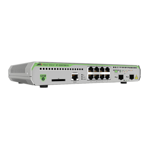
Figure 1: Front Panel............................................................................................................................................................18
Figure 2: Back Panel............................................................................................................................................................18
Figure 3: Link/Activity and Duplex Mode LEDs for the 10/100/1000Mbps Copper Ports .....................................................26
Figure 4: Link/Activity LEDs on the 1/2.5/5/10Gbps Copper Port.........................................................................................27
Figure 5: Link/Activity LED for the 1/10Gbps SFP+ Port......................................................................................................28
Figure 6: Switch ID LED.......................................................................................................................................................31
Figure 7: Switch ID LED With Low Power Mode Disabled ...................................................................................................31
Figure 8: Switch ID LED With Low Power Mode Enabled....................................................................................................32
Figure 9: x330-10GTX Switch Accessory Items...................................................................................................................44
Figure 10: Installation Options for the x330-10GTX Switch..................................................................................................45
Figure 11: Switch Installation on a Table..............................................................................................................................46
Figure 12: Unsupported Table Installations..........................................................................................................................46
Figure 13: Attaching the Bumper Feet..................................................................................................................................47
Figure 14: x330-10GTX Switch in an Equipment Rack with the RKMT-J05 Brackets Kit.....................................................50
Figure 15: x330-10GTX Switch with RKMT-J05 Cable Trays...............................................................................................51
Figure 16: Items in the RKMT-J05 Equipment Rack Brackets Kit........................................................................................52
Figure 17: Placing the x330-10GTX Switch Upside Down on a Table .................................................................................53
Figure 18: Removing the Feet from the x330-10GTX Switch...............................................................................................54
Figure 19: Attaching the RKMT-J05 Handles to the Short Brackets.....................................................................................54
Figure 20: Attaching the Short RKMT-J05 Brackets to the Long Brackets...........................................................................55
Figure 21: Attaching the RKMT-J05 Cord Trays to the Long Brackets.................................................................................56
Figure 22: Attaching the RKMT-J05 Brackets to the Switch.................................................................................................57
Figure 23: Attaching the x330-10GTX Switch to an Equipment Rack..................................................................................58
Figure 24: BRKT-J23 Bracket Kit..........................................................................................................................................60
Figure 25: x330-10GTX Switch Wall Installations with Two BRKT-J23 Brackets.................................................................60
Figure 26: x330-10GTX Switch Wall Installations with Four BRKT-J23 Brackets................................................................61
Figure 27: Invalid Wall Installation with Front Panel Facing Down.......................................................................................61
Figure 28: Marking the Screw Holes for Two BRKT-J23 Brackets.......................................................................................65
Figure 29: Marking the Screw Holes for Four BRKT-J23 Brackets ......................................................................................65
Figure 30: Attaching the Bottom BRKT-J23 Brackets to the Wall.........................................................................................66
Figure 31: Sliding the Switch into the BRKT-J23 Brackets...................................................................................................67
Figure 32: Attaching the Top BRKT-J23 Brackets to the Wall..............................................................................................68
Figure 33: Installing the Power Cord Retaining Clip.............................................................................................................70
Figure 34: Connecting the AC Power Cord ..........................................................................................................................71
Figure 35: Lowering the Power Cord Retaining Clip.............................................................................................................71
Figure 36: Connecting the Power Cord to an AC Power Source..........................................................................................71
Figure 37: Management Cable Included with Switch............................................................................................................73
Figure 38: VT-Kit3 Management Cable................................................................................................................................73
Figure 39: Management Workstation, VT-Kit3 Management Cable, and Switch..................................................................74
Figure 40: Connecting the Management Cable to the Console Port....................................................................................74
Figure 41: User Exec Mode Prompt .....................................................................................................................................75
Figure 42: Verifying the Switch ID LED................................................................................................................................76
Figure 43: Installing an SFP+ Transceiver ...........................................................................................................................80
Figure 44: Removing the Dust Cover from an SFP+ Transceiver ........................................................................................81
Figure 45: Positioning the SFP+ Handle in the Upright Position..........................................................................................81
Figure 46: Connecting a Fiber Optic Cable to an SFP or SFP+ Transceiver.......................................................................82
Figure 47: Installing an SP10TW Cable................................................................................................................................83
Figure 48: x330-10GTX Switch Dimensions.........................................................................................................................90
Figure 49: Pin Layout for the RJ-45 Copper Ports (Front View)...........................................................................................96
Figures
