Tindo Solar Karra Series User manual
INSTALLATION MANUAL
TINDO SOLAR PV Modules
Safety Notes
Installation of modules requires professional skills and knowledge and
is to be carried out by qualified personnel. Please read this manual
carefully before installing and using this module. Installation personnel
shall get familiar with mechanical and electrical requirements of this
system. Please keep this manual properly as reference for future
maintenance or upkeep or for sales and treatment of modules.
#1
APPLICABLE PRODUCTS
This document is applicable to the series of solar module as listed
below:
Karra – XXX (System Voltage 1000V Module)
Karra - XXXH (System Voltage 1500V Module)
Regular modules Mechanical drawing
#2
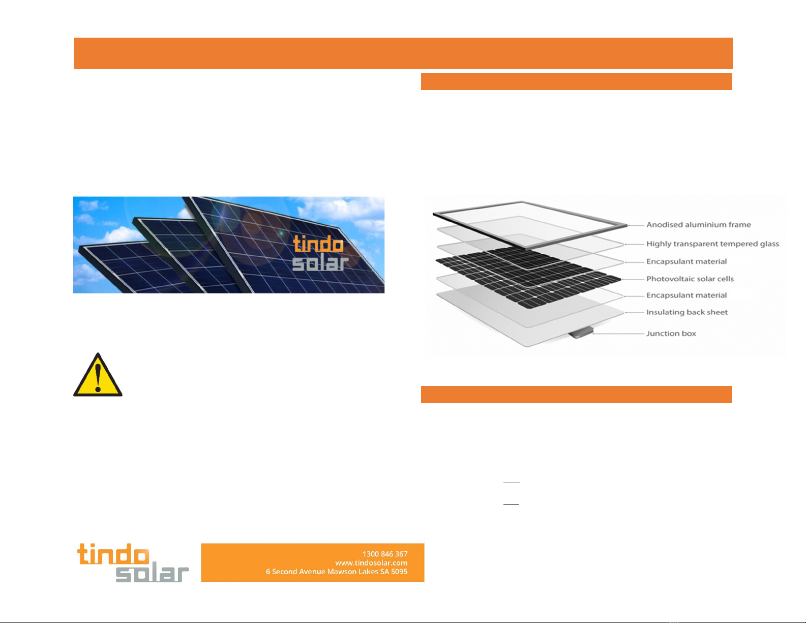
INTRODUCTION
Thank you for choosing a Tindo solar Module. Background to our
name “TINDO” – Tindo is a word from the Kaurna warra Aboriginal
language which is the language of the peoples indigenous to the
Adelaide plains on which our solar panel manufacturing plant sits.
Tindo
s
. sun; or watch; clock; day
Karra
s
. sky ; or height; heaven
INSTALLATION MANUAL
For our purposes we have taken Tindo as meaning the “SUN” and
Karra as “Sky”, thus you have purchased a panel made by the Sun and
a panel that comes from the Sky.
Tindo solar modules transform the sun’s light energy into electricity.
Please read the following instructions carefully. Failure to observe
them may result in bodily injury and property damage. This manual
only applies for installations in Australia.
And the installation altitude is up to 2000m.
This manual provides information on safety precautions to be used
during the handling and installation of the Tindo Karra panel along
with technical instructions to be followed during installation,
mounting, wiring and commissioning.
#3
GENERAL WARNING & CAUTION
Keep children and unauthorized people away from the
modules and work site.
Appropriate safety practices, suitable protective clothes and
safety equipment must be used.
Appropriate safety practices and equipment for working at
heights must be used.
Do not work alone. Always work with a team of at least two
people.
The modules are not suitable for mobile usage or for indoor
installations.
Transport the modules in its original packaging
Do not expose PV modules to concentrated sunlight with mirrors
or lenses.
The Tindo Karra solar panel should only be installed and
maintained by a qualified and licensed electrician with Clean
Energy Council Solar PV accreditation.
Make sure flammable gases are not generated near the
installation site. Do not install the modules near open flame and
flammable materials. Solar modules are not explosion-proof
operating equipment.
Artificially concentrated sunlight shall not be directed on the
module or panel
Front protective glass is utilized on module. Broken solar
module glass is an electrical safety hazard (may cause electric
shock and fire). These modules cannot be repaired and should
be replaced immediately.

INSTALLATION MANUAL
#4
BEFORE INSTALLATION
Contact local authorities to determine local laws, permits and
codes to make sure your installation is fully compliant.
Make sure to strictly follow the local and national regulations
for work safety and accident prevention.
Observe local regulations concerning fire protection
classification for rooftop installations.
Only install undamaged modules. Ensure that the junction
box, cable and connectors are undamaged prior to
installation.
Store the modules in cool dry rooms before installation.
#5
DURING INSTALLATION
There is a serious risk of various types of injury occurring
during the installation.
Do not work under rain, snow, hot or windy conditions.
The solar panels, tools and other materials must be dry during
installation.
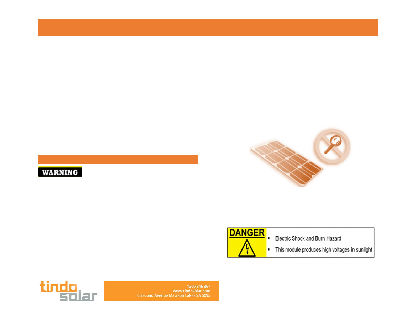
Completely cover the PV module surface with an opaque
material during the entire installation and wiring of the PV
module. Only then the module is reliably de-energised.
DANGER! Danger due to electric shock! A solar module
generates electricity and voltage even at a low intensity of
illumination. Arcing can occur when contacts in a live electrical
circuit are physically disconnected. This can result in grave or
mortal injury. The severity increases when several modules are
connected.
During installation at heights, there is a danger that tools,
panels or other materials could fall and injure people so take
necessary precautions by blocking off danger areas before
beginning work.
Panels must not be installed flat and need a minimum tilt of 5
degrees.
Materials : Fine-wire, tinned-copper conductor.
Only use PV-KST4 EVO 2, PV-KBT4 EVO 2 / Staubli(MC4).
Be very careful with the back of the module as the delicate
thin solar cells may break.
The PV panels are primarily made of glass and should be
handled with caution.
Ensure that adequate ventilation exists below the module to
help avoid elevated module temperatures.
Never touch the end of the connectors. Do not insert
electrically conductive parts into the plugs and junction box.
Do not touch the contacts or exposed terminals.
Do not twist the frame of the module or subject the module to
mechanical stress as the glass or solar cells may break.
Do not touch the PV module with bare hands as the frame has
sharp edges and may cause injury.
Do scratch or hit the back sheet or damage it
Do not stand or step on the module. Do not drop or place
objects on the modules.
Do not rest the module on its unprotected edges.
Do not drop tools or hard objects on PV modules.
Do not lift the modules by the cables or by the junction box.
Do not open the junction box under any circumstances.
Do not over bend the output cable as the insulation may
break down.
Do not drill holes in the aluminum frame.
Do not scratch the aluminum frame as it will cause corrosion
of the frame.

INSTALLATION MANUAL
Do not expose the modules to chemicals.
Do not place the modules in standing water. The junction box
is splash-proof only.
Bind cables to ensure cables are not drooping behind the
panels
Make sure cables are not exposed to direct sunlight as they
could be UV damaged.
Observe the local requirements for functional grounding or
earthing.
Observe the local requirements and regulations for lightening
protection.
#6
AFTER INSTALLATION
Make sure the PV connectors are tightly sealed and connected
properly. Do not disconnect or unplug the PV connectors
when the solar system is under load. Ensure that the modules
are first disconnected from the inverter prior to opening any
contacts in the solar installation. Be absolutely certain to
observe the time intervals specified by the manufacturer after
switching off the inverter and prior to starting subsequent
work such that the energized components can be discharged
In the case of the glass surface of the PV modules is broken,
make sure to be using the appropriate safety for the safe
removal of the panels. The panel could live so ensure it is
safely disconnected and isolated before touching the panel.
Wear rubber gloves for electrical insulation during service.
#7
ELECTRICAL INSTALLATION
Use proper electrically rated insulated tools and do not
use wet tools
TIndo Karra modules must not be connected in series and
parallel with other modules.
For series connections, make sure the maximum open
circuit Voltage is less than the specified maximum system
Voltage and use a safety factor of 1.25
For parallel connections, make sure cables are connected
according the Australian electrical wiring standards and
take proper measures to prevent reverse current flows.
Use a safety factory of 1.25
Ensure a safety factor of 1.25 when determining permitted
voltages for components, cable sizes, fuse sizes and
inverter sizes.
Class of protection against electrical shock : Class II
Solar panels must be installed in accordance with AS-5033
Installation of PV arrays. Other relevant standards are AS-
3000 Electrical Wiring Rules, AS-1768 Lightening
Protection, AS-1170.2 Wind Loads, AS-4777 Grid
Connections of Energy Systems via Inverters.
Do not pull the cables on the junction box as the cable
may disconnect and could cause electric shock.
Specifications for cables are Type Designation : H1Z2Z2-K
1x4㎟, Rated Voltage : DC 1.5kV / AC 1kV, Ambient
Temperature : -40℃ ~ +90℃, Conductor.
INSTALLATION MANUAL
#8
SITE SELECTION
Make sure panels are installed in an un-shaded location
throughout the year. Take into account both summer and
winter sun paths and shading. This will ensure maximum yield
from your solar panel. Avoid shading from chimneys, trees, air
conditioners and other objects.
If you are planning to install the PV modules in a salty
environment such as near the beach, please consult with
Tindo local agent first to determine whether or not the
installation is appropriate for the PV module.
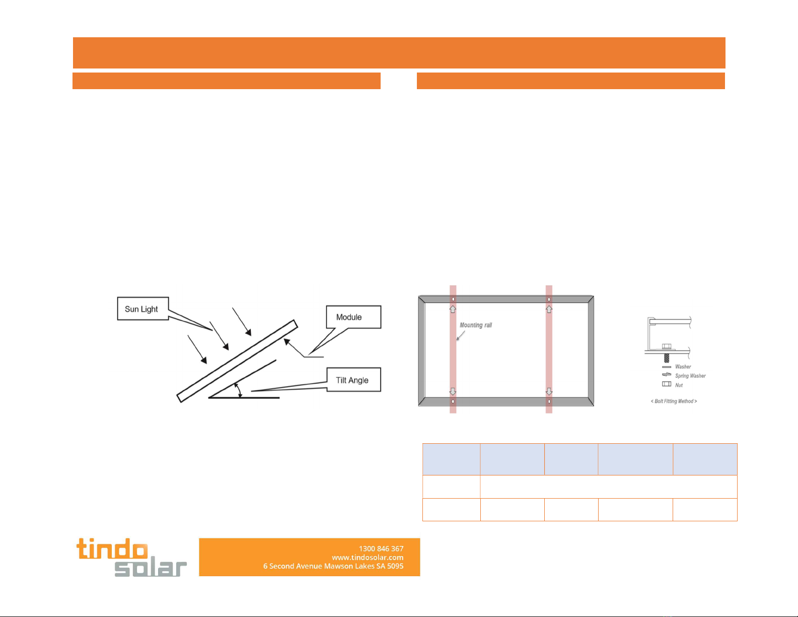
Make sure to tilt the solar panel so that the energy yield
throughout the year is maximized. As a rule of thumb, the tilt
angle should be approximately equal to the latitude of the
installation location.
The modules are certified according to the norm IEC 61215,
IEC 61730-1 and IEC 61730-2 for safe operation in moderate
climates.
The permitted module temperatures lie between -40 °C and
+85 °C.
#9
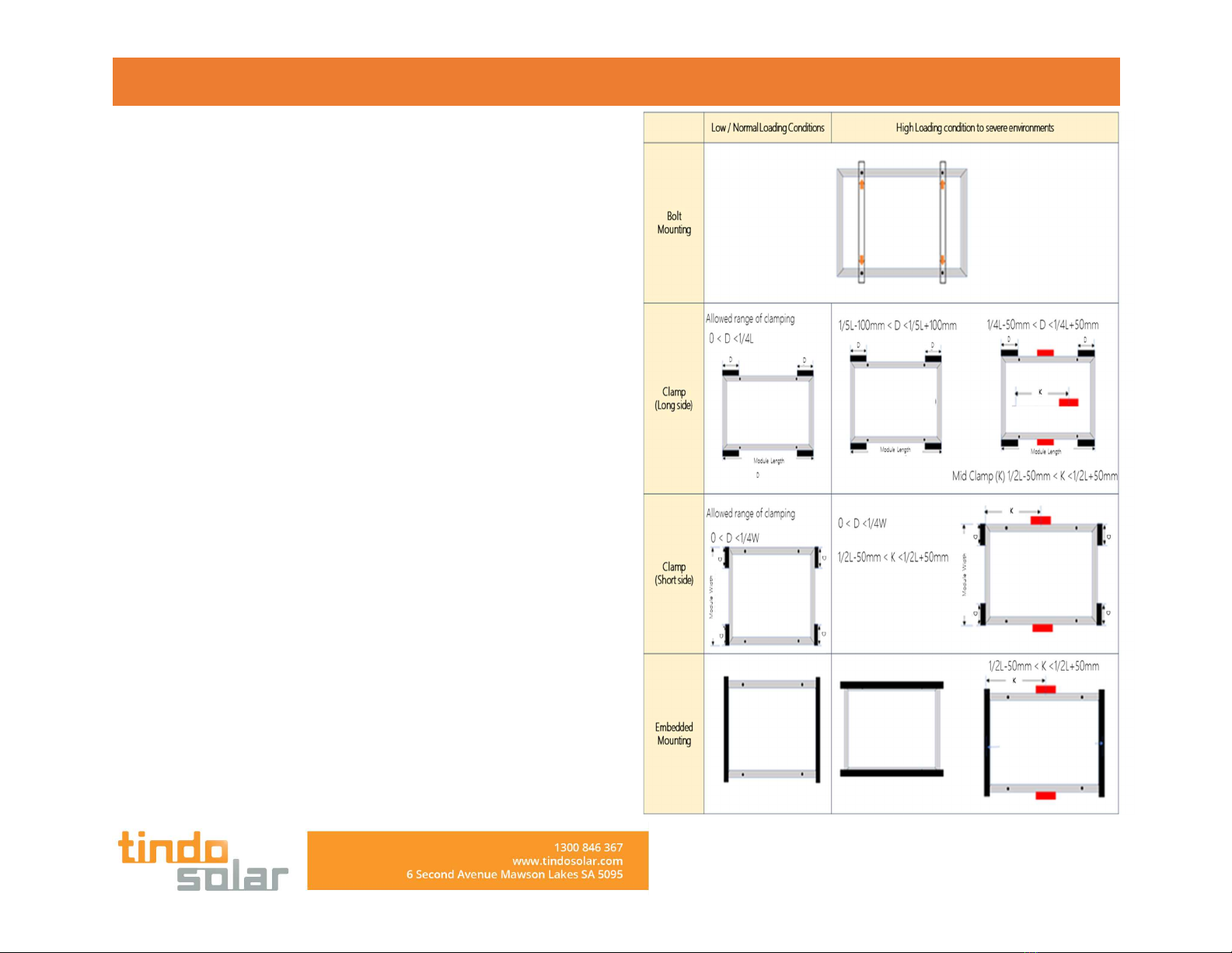
INSTALLATION METHODS
Solar Panel and mounting system ca be fix by mounting holes or
clamps. The installations shall be carried out as the illustrations and
suggestions.
Only use genuine Tindo Mounting hardware for mounting the solar
panel. Support structures that the PV modules are mounted to must
be absolutely rigid.
[Install modules through mounting holes]
Make use of bolts to fix modules on the mounting system through
frame mounting holes on the back of the module frame. This applies
to both portrait and landscape installation orientations. Use four
mounting holes.
Accessories recommended as follows:
Bolt Washer Spring Washer Nut
Material Stainless steel
Dimension
M8 x 16mm M8 M8 M8
INSTALLATION MANUAL
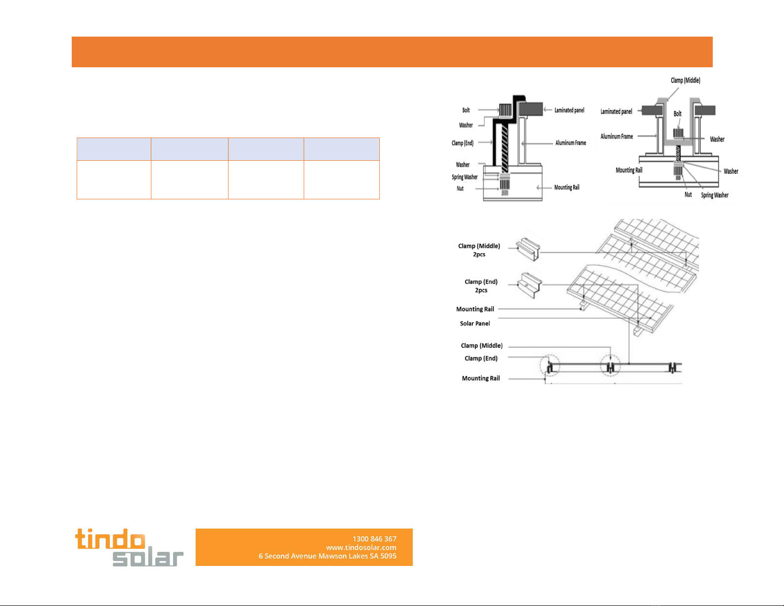
Torque for fastening bolts: 16Nm~ 20Nm
[Install modules with clamps]
Install modules on the mounting system with clamps. (Bolt M8)
Width Thickness Material
Spec No less than
40mm
No less than
3mm
Aluminum
6063-T5
Torque for fastening bolts: 18Nm~ 24Nm
The clamps shall not contact glass or module frame deformed in any
case. The contacting surface of the clamp contacting the front side the
frame shall be even and smooth. Otherwise, the frame and module
may be damaged. Make sure the clamp will not produce any shading
effect.
Approved clamping areas are shown in the following drawing. The
dimensions refer to the distance from the edge of the module to the
center of the clamp. This applies to both portrait and landscape
installation orientations.
[ Mounting details]
Low/ normal loading conditions apply to most environments: the
maximum static pressure on the back side of the module is 2400Pa
and the maximum static pressure on the front side is 5400Pa.
[ Position of Fixing Points ]
Low/normal loading conditions apply to most environments:
the maximum static pressure on the backside of the module
is 2400pa (equal to wind load) and the maximum static
INSTALLATION MANUAL
pressure on the front side is 2400pa (equal to wind load and
snow load).
High loading conditions apply to severe environments (such
as wind storm, heavy snow): the maximum static pressure on
the backside of the module is 2400pa (equal to wind load)
and the maximum static pressure on the front side is 5400pa
(equal to wind load and snow load), which is the highest
requirement on pressure in the IEC standards.
INSTALLATION MANUAL
The modules can be installed in landscape or portrait. Make
sure the junction box is positioned in the upper area of the
modules with the wires hanging down.
Ensure the drain holes in the solar panel frame are
unobstructed to allow drainage of water.
Install panels with a minimum tilt of 5 degrees.
Install panels with a minimum distance of 10mm between
modules.
Ensure the panel and array conforms to local environmental
codes especially for wind loading.
Do not allow dissimilar metals to be in contact with each other
giving rise to galvanic corrosion.
Mechanical Load Test Condition
Clamping Installation Bolting Installation
Test Side Front Back Front Back
Design Load 3600 Pa 1600 Pa 3600 Pa 1600 Pa
Safety Factor 1.5 1.5 1.5 1.5
Test Load 5400 Pa 2400 Pa 5400 Pa 2400 Pa
#10
ELECTRIC INSTALLATION
[ Electric Performance ]
Module electric performance parameters such as Isc, Voc and Pmax
nominal values have ±3% error with those under standard testing
conditions of: irradiance of 1000 W/m2, cell temperature of 25℃ and
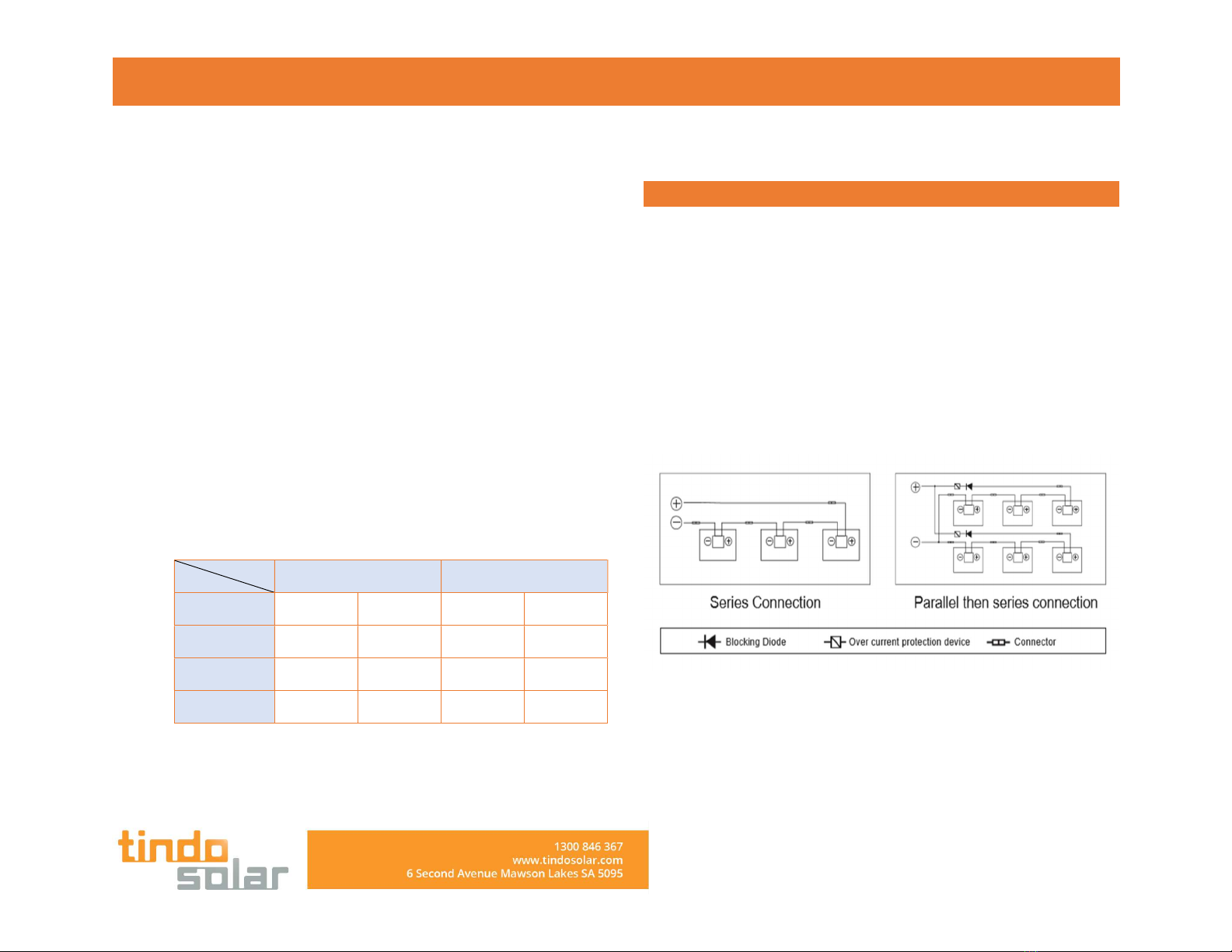
air mass of AM1.5. When modules are in series connection, the final
voltage is sum of that of the single module. When modules are in
parallel connection, the final current is sum of the single module as
below shows. Modules with different electric performance models
cannot be connected in series.
Series connection and parallel connection circuit diagram
The number of modules in series connection in each strand shall be
calculated according to relative regulations. The open circuit voltage
value under the expected lowest temperature shall not exceed the
maximum system voltage value stipulated for modules and other

INSTALLATION MANUAL
values required by DC electric parts. (modules maximum system
voltage is DC1000V/DC1500V---actually system voltage is designed
based on the used modules model and inverter.)
The VOC factor can be calculated with the following formula. Voc=1-
βVoc×(25-T) T: The expected lowest temperature of the installation
site. β:VOC temperature coefficient (% /℃) (Refer to modules manual
for further detail)
[ Cables and Connecting Lines ]
In module design, adopt enclosed junction boxes with the protective
level of IP67 for on-site connection to provide environmental influence
protection for wires and connections and contacting protection for
non-insulating electric parts. The junction box has well connected
cables and connectors with the protective level of IP67. These designs
facilitate parallel connection of modules. Each module has two
independent wires connecting the junction box, one is negative pole
and the other is positive pole. Two modules can be in series
connection by inserting the positive pole at one end of wire of one
module into the negative pole of the adjoining module.
According to local fire protection, building and electrical regulation,
apply proper cable and connector; ensure the electrical and
mechanical property of the cables (the cables should be coated in a
catheter with anti-UV aging properties, and if is exposed to air, the
cable itself should have anti-UV aging properties).
[ Connector ]
Please keep connectors clean and dry. Make sure connector nuts are
fastened before connection. Do not connect connectors that are damp
or dirty or under any other improper conditions. Avoid connectors
from direct sun light and water immersion or falling onto ground or
roof. Wrong connection may lead to electric arc and electric shock.
Please make sure that all electric connection is reliable. Make sure all
connectors with lock are fully locked.
[ Bypass diode ]
Solar module junction box contains bypass diode which is in parallel
connection with the cell strands. If heat spot occurs locally with the
module, the diode will come into operation to stop the main current
from flowing through the heat spot cells in order to restrain module
heating and performance loss. Notice, bypass diode is not the
overcurrent protection device. If the diode is found or doubted to be
out of order, the installer or system maintenance supplier shall contact
us. Please do not try to open the module junction box on your own.
[ Grounding ]
In design of modules, the anodized corrosion resistant aluminum alloy
frame is used for rigidity support. For safety utilization and to protect
modules from lightning and static-electricity damage, the module
frame shall be grounded. The grounding device shall be in full contact
with inner side of the aluminum alloy and penetrate the frame surface
oxide film. Do not drill additional grounding holes on module frame.
The grounding conductor or strap may be copper, copper alloy, or any
other material acceptable for use as an electrical conductor per
respective National Electrical Codes. The grounding conductor must

INSTALLATION MANUAL
then make a connection to earth using a suitable earth ground
electrode. Holes marked with a grounding mark on the frame can only
be used for grounding and not for component mounting. Frameless
double glass modules have no exposed conductor, and therefore
according to regulations it did not need to be grounded.
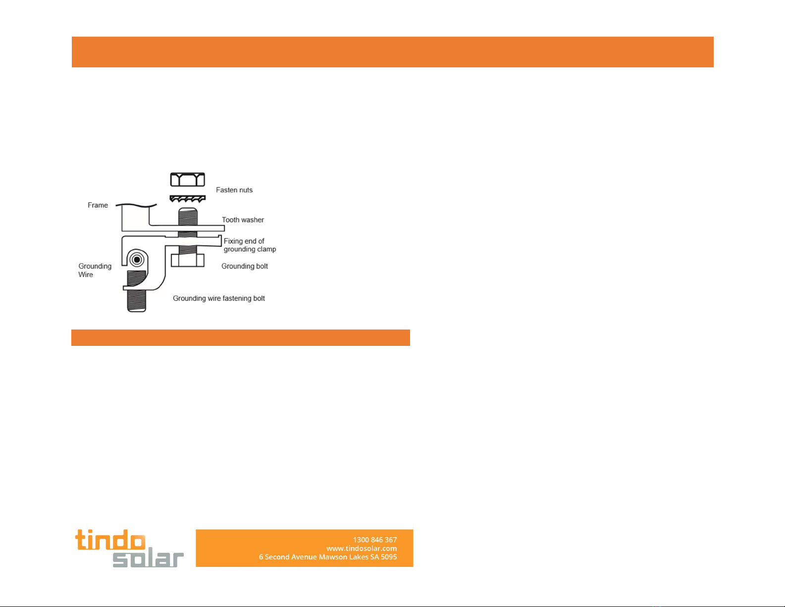
[ Grounding methods below are permissible ]
Grounding by grounding clamp
There is a grounding hole with the diameter of Ø4.2 mm at the edge
of the module back frame. The central line of the grounding sign also
located on the edge of the module back frame overlaps with that of
the grounding hole. Grounding between modules shall be confirmed
by qualified electricians and grounding devices shall be manufactured
by qualified electric manufacturer. The torque is recommended to be
2.3N•m. 12 AWG copper core wire is used for the grounding clamp.
And copper wires cannot be pressed damaged during installation.
Grounding by unoccupied mounting holes
Mounting holes on modules that are not occupied can be used for
installing grounding devices.
Align grounding clamp to the frame mounting hole. Use
grounding bolt to go through the grounding clamp and
frame.
Put the tooth side of the washer on the other side and fasten
the nuts.
Put grounding wires through the grounding clamp and
grounding wire material and dimension shall meet
requirements in local national and regional law and
regulations.
Fasten bolts of grounding lines and installation ends.
Grounding Clamp Installation Note: TYCO. 1954381-1 (recommended) is used in figures above
INSTALLATION MANUAL
[ Install Method ]
#11
CLEANING & MAINTENANCE
TIndo panels are designed and built for long life and require minimal
maintenance.
Most dirt is washed off the panel by rain. If dirt builds up becomes
excessive:
• wash or rinse of the panel to remove dust, dirt or other deposits with
water.
• clean the glass surface only with soft cloth using warm water or
ethanol.
• no aggressive cleaner such as alkali chemicals including ammonia-
based products on panel.
The solar system should be inspected annually by a specialist installer
for:
• secure fastening and corrosion-free system components.
• secure connection, cleanliness and integrity of all electrical
components.
• the contact resistances of the grounding.
[ Module Appearance Inspection ]
Check module appearance defects visually, especially:
Module glass cracks.
Corrosion at welding parts of the cell main grid: it is caused by
moisture into the module due to damage of surface
packaging materials during installation or transportation.
Check whether there are traces of burning on the module
back plate.
Check PV modules for signs of aging including rodent
damage, weather damage, connection tightness, corrosion
and grounding condition.
Check for any shape objects in contact with PV modules’
surface
Check for any obstacles shielding the PV modules
Check for any loose or damage screws between the modules
and bracket. If so, adjust and fix on time.
Check connector sealing and cable connection.
INSTALLATION MANUAL
Look for gap on the sealant of the terminal box and confirm
whether it is cracking.
#12
MODULING HANDLING
[ Safety ]
• Solar panel weight up to and over 20kg, and at over 1.5m long can
be cumbersome to handle. Care should be taken to avoid injury.
• It is hazardous to install solar panels in high wind conditions.
• It is hazardous to install solar panels in wet weather.
[ General ]
• Take care when transporting and handling solar panels. Many issues
caused by rough handling will arise years after the installation. Taking
additional care can save considerable time and money from avoided
service calls and replacements.
• Never walk on a solar module
• Never drop a heavy object on a solar module
• Do not work on the modules with sharp objects
• Record module serial numbers for system documentation
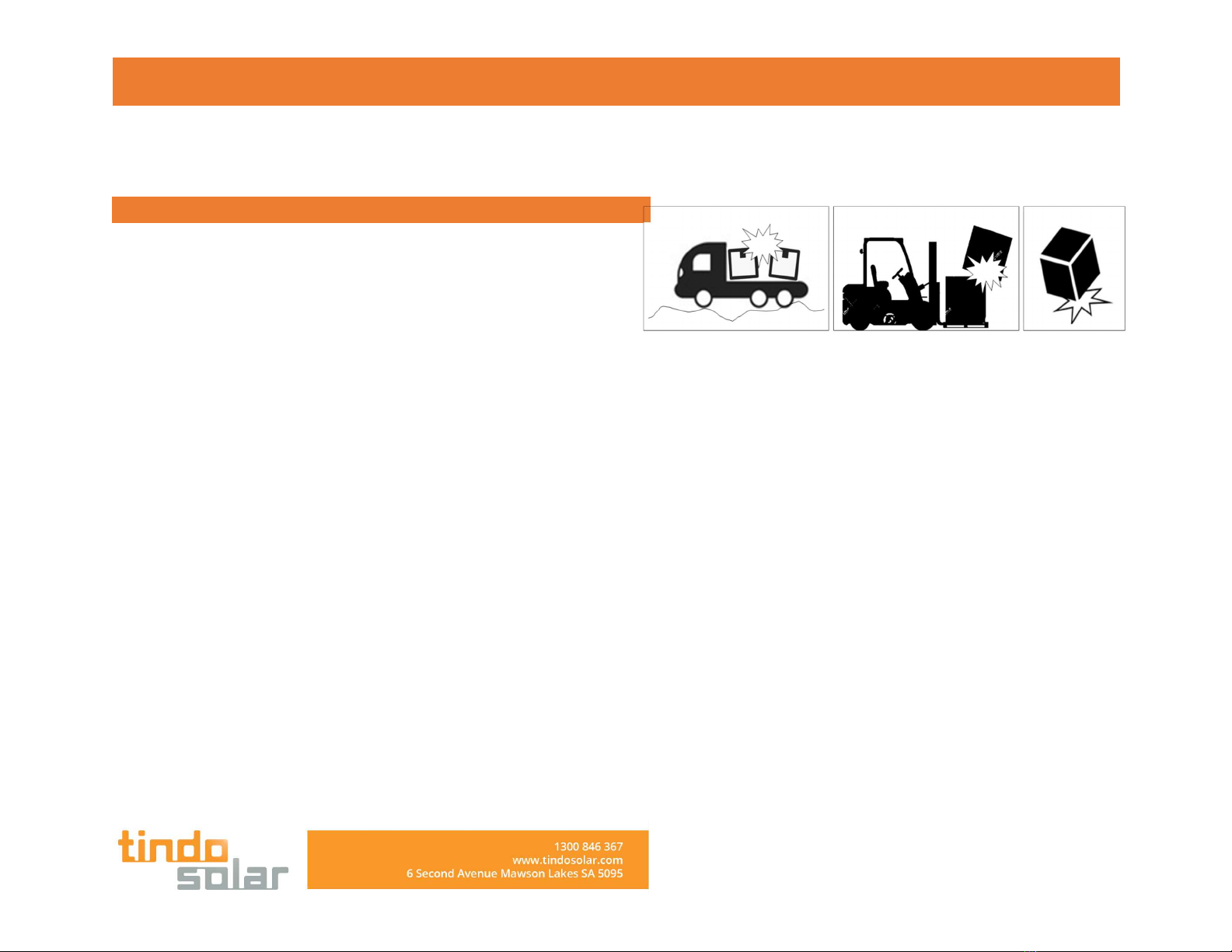
[ Transport ]
• Transport vehicles and equipment should be fit for purpose ad well
maintained.
• Treat boxes and pallets with care, do not drop or allow the boxes to
receive impacts.
• Any panels transported outside of their boxes should be properly
secured and not allowed to move independently
[ Module Appearance Inspection ]
Check module appearance defects visually, especially:
• Module glass cracks.
• Corrosion at welding parts of the cell main grid: it is caused by
moisture into the module due to damage of surface packaging
materials during installation or transportation.
• Check whether there are traces of burning on the module back plate.
• Check PV modules for signs of aging including rodent damage,
weather damage, connection tightness, corrosion and grounding
condition.
• Check for any shape objects in contact with PV modules’ surface
• Check for any obstacles shielding the PV modules
INSTALLATION MANUAL
• Check for any loose or damage screws between the modules and
bracket. If so, adjust and fix on time.
• Check connector sealing and cable connection.
• Look for gap on the sealant of the terminal box and confirm whether
it is cracking.
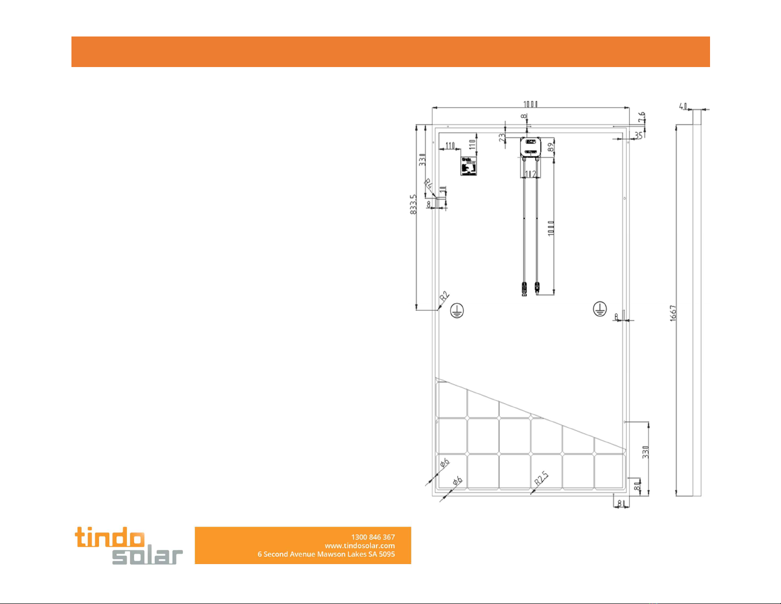
[ MODULE DRAWING: Karra 60cells series ]
INSTALLATION MANUAL
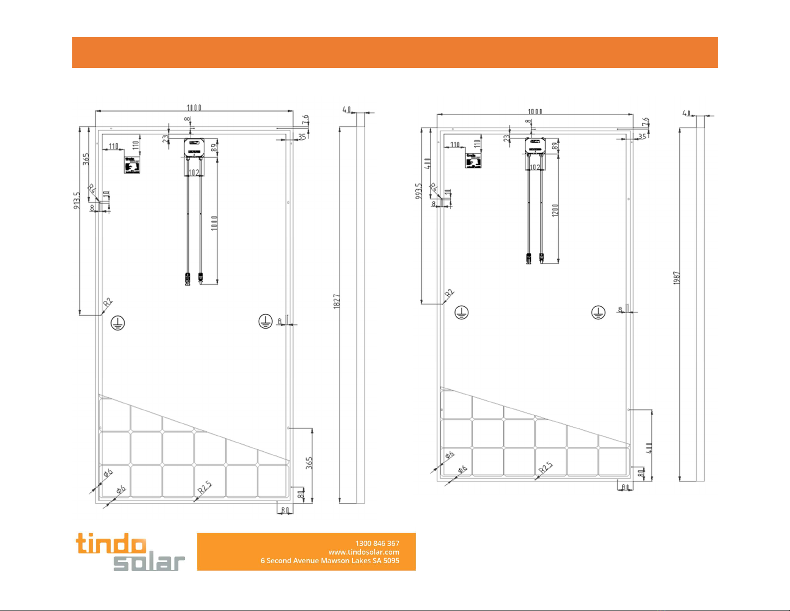
[ MODULE DRAWING: Karra 66cells series ]
[ MODULE DRAWING: Karra 72cells series ]

INSTALLATION MANUAL
Tindo Operations Co Pty Ltd
5 / 6- 8 Second Avenue Mawson Lakes South Australia 5095
Contact : info@tindosola.com, Ph. Office : +61 1300 846 367
This document is subject to change without notice.
This manual suits for next models
2
Table of contents


