Tinius Olsen L Series User manual

Unit 6 Perrywood Business Park, Honeycrock Lane, Salfords, Surrey, RH1 5DZ, England, UK
Telephone: +44 1737 765001 Facsimile: +44 1737 764768 Website: www.tiniusolsen.com
L-Series Tensile Test Machines
Instructions For Use
Issue 01

© Tinius Olsen Ltd L-Series Manual – Issue 1 Page 2 of 31
Contents
1.
Introduction...................................................................................................................................3
2.
Specifications ...............................................................................................................................4
2.1.
Load Frame................................................................................................................................4
2.2.
Control Panel..............................................................................................................................4
2.3.
Force Measurement ...................................................................................................................4
2.4.
Extension Measurement ............................................................................................................5
2.5.
Speed Control ............................................................................................................................5
2.6.
Hardware Options ......................................................................................................................5
2.7.
Dimensions.................................................................................................................................5
2.8.
Temperature...............................................................................................................................6
2.9.
Humidity .....................................................................................................................................6
2.10.
Power .........................................................................................................................................6
2.11.
Machine Supply Requirements ..................................................................................................6
2.12.
CE Mark .....................................................................................................................................6
2.13.
Manufacture ...............................................................................................................................6
3.
Unpacking the Material Testing Machine...................................................................................7
3.1.
H1KL & H5KL.............................................................................................................................7
3.2.
H10KL, H25KL & H50KL..........................................................................................................10
4.
Contents ......................................................................................................................................13
4.1.
Checking Contents...................................................................................................................13
5.
Machine Installation ...................................................................................................................15
5.1.
Location....................................................................................................................................15
5.2.
Mains Supply............................................................................................................................15
5.3.
Warning Symbols .....................................................................................................................16
5.4.
Connection to Supply ...............................................................................................................16
5.5.
Fitting Load Cell .......................................................................................................................17
5.6.
Connection to PC .....................................................................................................................18
6.
Power ON Checks.......................................................................................................................20
6.1.
Emergency Stop Switch ...........................................................................................................20
6.2.
Power ON/OFF Switch.............................................................................................................20
6.3.
Mechanical Limit Switches .......................................................................................................21
6.4.
Crosshead Control Keys ..........................................................................................................22
6.5.
Alarms ......................................................................................................................................23
6.6.
Auxiliary Equipment..................................................................................................................25
7.
Installation of Tooling ................................................................................................................26
7.1.
Attachment Parts......................................................................................................................26
7.2.
Method .....................................................................................................................................26
7.3.
Tooling Alignment.....................................................................................................................27
8.
Operator Safety...........................................................................................................................29
8.1.
Protective Screens ...................................................................................................................29
8.2.
Operator Training .....................................................................................................................29
9.
Routine Maintenance .................................................................................................................30
9.1.
Electrical...................................................................................................................................30
9.2.
Calibration ................................................................................................................................30
9.3.
Lubrication................................................................................................................................31
9.4.
Machine Storage ......................................................................................................................31

© Tinius Olsen Ltd L-Series Manual – Issue 1 Page 3 of 31
1. Introduction
This manual is to help the operator understand the operation of the L-Series Universal Testing
Machine. The L-Series range of machines are designed to operate with an external personal
computer (PC). Software is supplied to enable the machine to conduct tests in the chosen
materials. The software operates under the Microsoft Windows environment.
The L-Series range of testing machines with their versatile, easy-to-use software package are
ideal for determining the mechanical and physical properties of materials in Tension,
Compression, Flexure and Shear. Many other physical properties may also be investigated.
There are five machine capacities in the L-Series range. These are H1KL (1000N), H5KL
(5000N), H10KL (10KN), H25KL (25KN) and H50KL (50KN). All machines are similar in
functionality and are supplied with the same auxiliary interface. The L-Series range of testing
machines employs two load frame configurations. A single screw arrangement for low capacity
machines (H1KL and H5KL) and a twin screw arrangement for high capacity machines
(H10KL,H25KL and H50KL)
All L-Series machines are supplied with an external Power Transformer. The standard power
transformer is designed to operate from a 230V 50Hz public network supply. The output of the
power transformer is 48V AC and is used to power the testing machine. The power transformer
can be supplied for different public network supply voltage and frequency’s, (110V 60Hz)
however this must be specified when ordering
There may be aspects of material testing not covered in this operation manual in particular the
type of grips used and additional optional equipment, such as Extensometers, Printers, etc. See
the accessory instructions provided for these options.

© Tinius Olsen Ltd L-Series Manual – Issue 1 Page 4 of 31
2. Specifications
2.1. Load Frame
2.1.1. Capacity
H1KL Capacity 1kN (100kg)
H5KL Capacity 5kN (500kg)
H10KL Capacity 10kN (1000kg)
H25KL Capacity 25kN (2500kg)
H50KL Capacity 50kN (5000kg)
2.1.2. Style
Vertical Bench Mounting
2.1.3. Construction
(H1 &5 KL) Cast Aluminium crossheads with sheet steel panelling
(H10,25 & 50KL) Solid steel -crossheads with sheet steel panelling
Precision Ball Screws
Ballscrew cover/protection bellows
Pre-loaded Lead Screw Thrust Races
Precision DC Servo Motor
Programmable crosshead Limit Switches
Emergency Stop Switch
2.1.4. Travel & Stiffness
H1KL Maximum crosshead travel excluding grips is 445mm
Maximum Test Specimen Diameter 150mm
Frame Stiffness 2kN/mm at normal load points
H5KL Maximum crosshead travel excluding grips is 750mm
Maximum Test Specimen Diameter 200mm
Frame Stiffness 7kN/mm at normal load points
H10KL Maximum crosshead travel excluding grips is 1100mm
Distance between Columns 405mm
Frame Stiffness 100kN/mm at normal load points
H25KL Maximum crosshead travel excluding grips is 1100mm
Distance between Columns 405mm
Frame Stiffness 100kN/mm at normal load points
H50KL Maximum crosshead travel excluding grips is 1075mm
Distance between Columns 405mm
Frame Stiffness 100kN/mm at normal load points
2.2. Control Panel
Crosshead Up, Down, Stop and Test Keys
LED Direction and Alarm indicators
1 Auxiliary option slot for external equipment
High Speed RS232 Interface Port
16 Bit Microcontroller
Audible alarms
System Watch Dog Timer
2.3. Force Measurement
Load Cell Z Beam Construction
Conforms to EN10002, ASTM E4, DIN 51221, ISO 75001
Range 2% to 100% with Guaranteed Accuracy of 0.5% of applied force
Extended Range down to 1% with Guaranteed Accuracy of 1%
Rapid Change Load Cells Available:-
50kN, 25kN, 10kN, 5kN, 2.5kN, 1kN,

© Tinius Olsen Ltd L-Series Manual – Issue 1 Page 5 of 31
500N, 250N, 100N, 50N, 25N, 10N, 5N
Digital Encoding for automatic load cell recognition
Automatic Load Cell Protection system, Triggered at 9% above load cell capacity.
Force sampling rate typically 200 Times per Second
Load cell resolution 1 part 64,000 (Tension or Compression)
Digital Load Tear ±20% whilst maintaining full load cell capacity
2.4. Extension Measurement
Extension Measurement by Precision optical encoder
Single measurement range 0 to 1000mm
Resolution 0.0001mm accuracy 0.01mm/300mm
2.5. Speed Control
2 Default Test Speeds (5 mm/min & 100 mm/min)
1 Default Jog Speed (1 mm/min)
Dual Speed Function whilst under test
Speed Velocity Programmable in 0.001 mm/min steps
Speed accuracy ±0.05% of full speed
32 Bit Precision Motor Controller
Drive system:- DC 4 Quadrant Motor Drive
Automatic Over/Under Speed Alarms
Motor Drive Alarms on Under/Over Voltage, Current, and Temperature
2.5.1. Velocity Speed Range
H1KL 0.001 mm/min to 500 mm/min (up to 500N)
0.001.mm/min to 1000 mm/min (up to 1kN)
Return Speed. 0.001 mm/min to 1500 mm/min
Jog Speed. 0.001 mm/min to 1000 mm/min
H5KL 0.001 mm/min to 500 mm/min (up to 2.5kN)
0.001.mm/min to 1000 mm/min (up to 5kN)
Return Speed. 0.001 mm/min to 1500 mm/min
Jog Speed. 0.001 mm/min to 1000 mm/min
H10KL 0.001 mm/min to 500 mm/min (up to 5kN)
0.001.mm/min to 1000 mm/min (up to 10kN)
Return Speed. 0.001 mm/min to 1000 mm/min
Jog Speed. 0.001 mm/min to 1000 mm/min
H25KL 0.001 mm/min to 500 mm/min (up to 10kN)
0.001.mm/min to 1000 mm/min (up to 25kN)
Return Speed. 0.001 mm/min to 1000 mm/min
Jog Speed. 0.001 mm/min to 1000 mm/min
H50KL 0.001 mm/min to 250 mm/min (up to 25kN)
0.001.mm/min to 500 mm/min (up to 50kN)
Return Speed. 0.001 mm/min to 500 mm/min
Jog Speed. 0.001 mm/min to 500 mm/min
2.6. Hardware Options
Tinius Olsen range of Clip on Extensometers
Tinius Olsen range of Displacement Transducers
Tinius Olsen range of Grips and Attachments
Clear protective screen
Dust cover
2.7. Dimensions
H1KL Height 820 mm Width 360 mm Depth 360 mm Weight 25kg
H5KL Height 1140 mm Width 490 mm Depth 360 mm Weight 50kg
H10KL Height 1575 mm Width 650 mm Depth 450 mm Weight 115kg
H25KL Height 1575 mm Width 650 mm Depth 450 mm Weight 117kg
H50KL Height 1620 mm Width 720 mm Depth 500 mm Weight 180kg

© Tinius Olsen Ltd L-Series Manual – Issue 1 Page 6 of 31
2.8. Temperature
Operating 0°C to 38°C
Storage -10°C to 45°C
2.9. Humidity
10% to 90% Non-Condensing Wet Bulb Method
2.10. Power
External Power Transformer
H1KL Type TX****-H1KL
H5KL Type TX****-H5KL
Input Supply Voltage 230V +/- 10% 50/60Hz
Output Voltage 48v 50/60Hz @ 330VA
Internally Fused(5x20mm HRC 3.15A Type (T) for 230V Supply)
H10KL Type TX****-H10KL
H25KL Type TX****-H25KL
H50KL Type TX****-H50KL
Input Supply Voltage 230V +/- 10% 50/60Hz
Output Voltage 48v 50/60Hz @ 530VA
Internally Fused(5x20mm HRC 6.30A Type (T) for 230V Supply)
2.11. Machine Supply Requirements
H1KL 48v +/-10% 50/60Hz @ 330VA
H5KL 48v +/-10% 50/60Hz @ 330VA
H10KL 48v +/-10% 50/60Hz @ 530VA
H25KL 48v +/-10% 50/60Hz @ 530VA
H50KL 48v +/-10% 50/60Hz @ 530VA
2.12. CE Mark
EMC Directive 89/336/EEC, and conforms to the following Generic EMC specification for
Commercial and Light Industrial products.
Emissions EN 50081-1,
Immunity EN 50082-1
Low Voltage Safety Directive 73/23/EEC, and conforms to the following specification.
EN 61010-1 (Safety requirements for Measurement, Control and Laboratory use)
2.13. Manufacture
TINIUS OLSEN LTD,
6 Perrywood Business Park,
Honeycrock Lane,
Salfords, Redhill,
Surrey, RH1 5DZ, England.
Tel. 01737 765001 Fax 01737 764768
© Tinius Olsen Ltd L-Series Manual – Issue 1 Page 7 of 31
3. Unpacking the Material Testing Machine.
3.1. H1KL & H5KL
Save all packing materials. You may need to re-pack and transport your Materials Testing
Machine at a later date
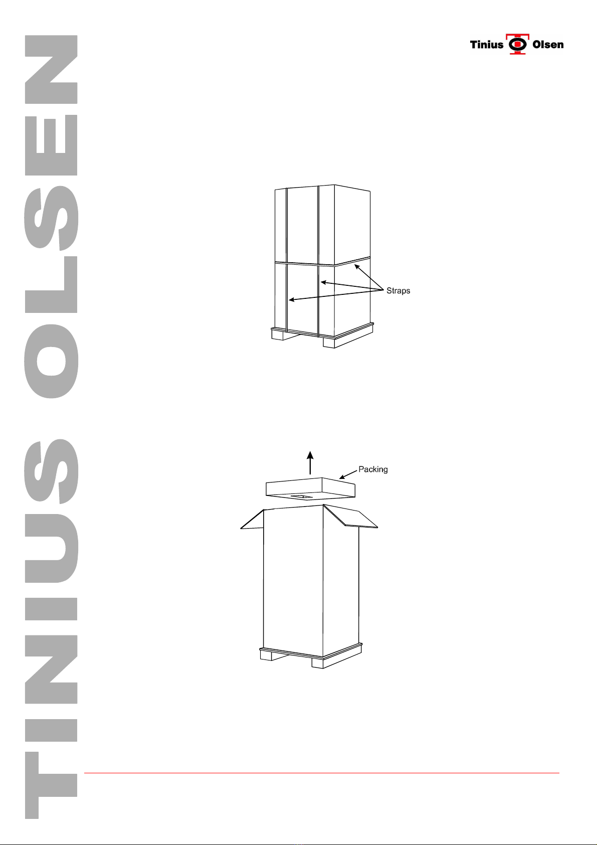
The machine is delivered packed in a Tri-wall cardboard case. This case has pallet style blocks
at its base enabling the case to be moved with a fork lift truck.
The diagram below shows the machine as delivered.
3.1.1. Cut all straps.
Care must be taken as these straps are under tension.
3.1.2. Cut tape at top of case to enable the access and remove internal top packing.
The diagram below indicates packing to be removed.

© Tinius Olsen Ltd L-Series Manual – Issue 1 Page 8 of 31
3.1.3. Remove case by lifting it upwards.
Care must be taken as internal cartons may have become dislodged.
The diagram below indicates the direction of case removal.
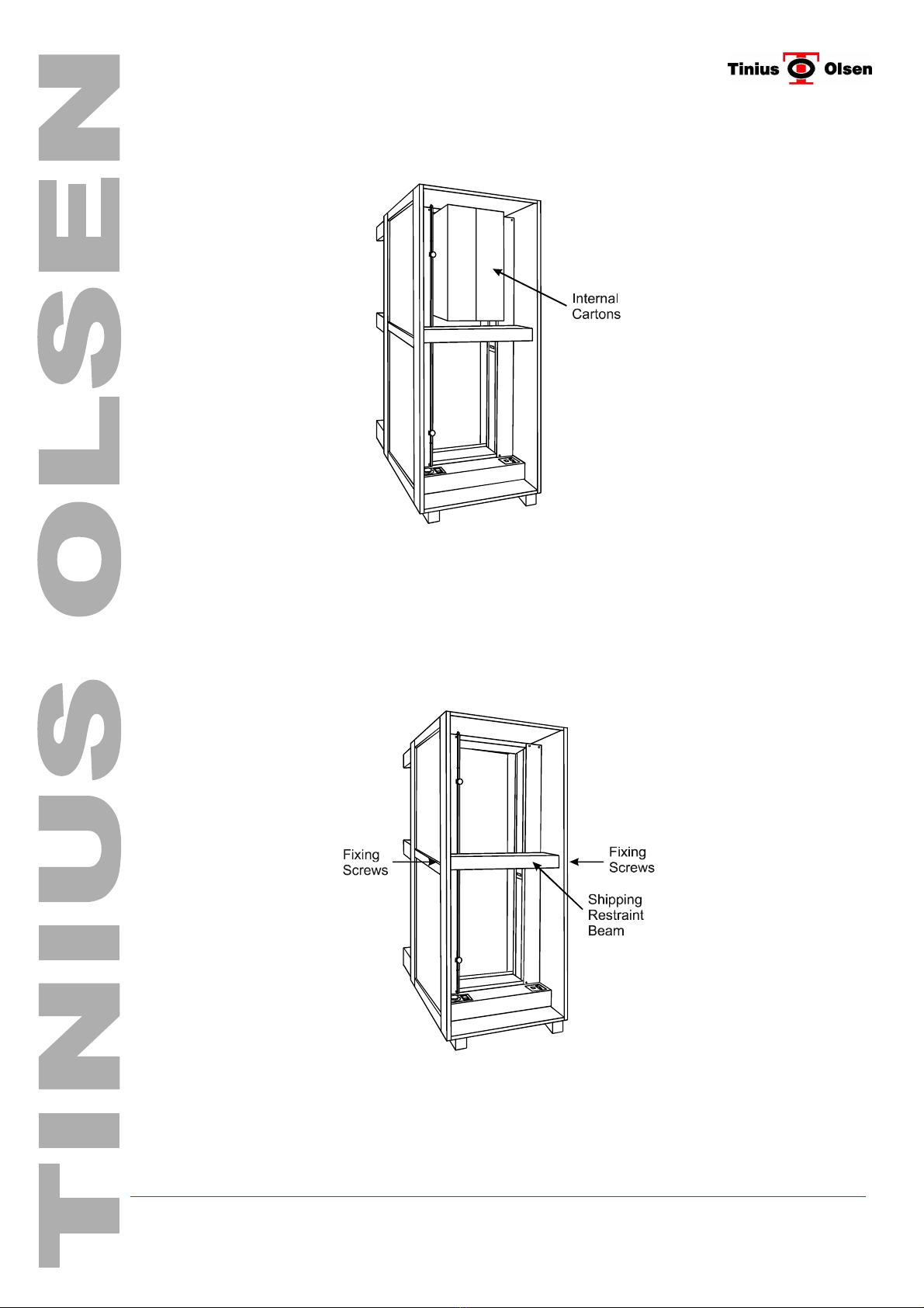
3.1.4. Remove internal cartons.
Care must be taken when removing these cartons as they may be heavier than first
expected.
The diagram below indicates the location of internal cartons.
3.1.5. Remove base packing from the machine by lifting the machine vertically.
Whilst carying out this operation it is an ideal opportunity to transfer the machine to the
prepared location.
Caution This material testing machine weighs 50Kg/110 pounds. It is
recommended two or more people carry out this operation.
The diagram below shows the machine with its packing removed.

© Tinius Olsen Ltd L-Series Manual – Issue 1 Page 9 of 31
3.1.6. Remove the protective packing around the electronic control panel.

© Tinius Olsen Ltd L-Series Manual – Issue 1 Page 10 of 31
3.2. H10KL, H25KL & H50KL
Save all packing materials. You may need to re-pack and transport your Materials Testing
Machine at a later date
The machine is delivered packed in a wooded case. This case has pallet style blocks on its
back and bottom sides enabling a fork lift truck to be used when manoeuvring the case.
The packing case has been designed so that it can be shipped on its back. This is to enable
easier transportation for air shipment etc.
The diagram below shows the machine as delivered.
3.2.1. Place Upright
Before attempting to unpack the machine, the case must be stood on end, bottom end
indicated by pallet style blocks. Rotating the case to its upright position should not be
attempted by hand and will require a overhead hoist or fork lift truck.
The diagram below the machine in its up-right position.
3.2.2. Open Case
Remove all screws around the edge of the panel and remove side. Care must be taken
when detaching the side as internal cartons may have become dislodged.
© Tinius Olsen Ltd L-Series Manual – Issue 1 Page 11 of 31
Remove all internal cartons. Care must be taken when removing these cartons as they
may be heavier than first expected.
The diagram below indicates the position of additional cartons.
3.2.3. Remove Constraints
The machine is held in position by packing material at top and bottom and by a shipping
restraint beam mounted at the machines crosshead. Remove the shipping restraint
beam. This beam is held in position by screws each side of the case. Finally remove all
packing material.
The diagram below indicates the shipping restraint bead to be removed.
© Tinius Olsen Ltd L-Series Manual – Issue 1 Page 12 of 31
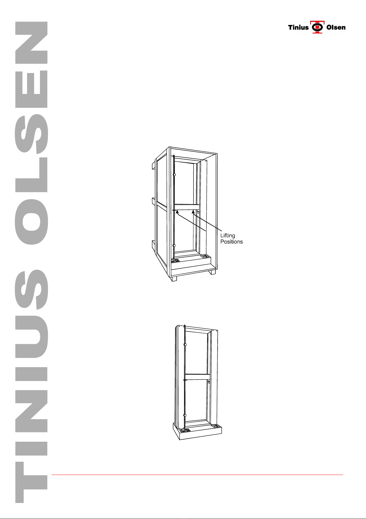
3.2.4. Remove Machine
The machine is now in a position to be removed from the case. Position the fork lift
truck, in front of the case.
Arrange the forks of the truck so that they can fit between the side covers of the
machine and below the crosshead. Slowly move the fork lift truck towards the machine
ensuring the forks do not hit the machine side covers. Raise the forks to lift the machine
so that its base is clear of the case, then remove the machine form the case.
Note To stop damage to the paint work on the machines crosshead place strips of
cardboard on the forks before lifting.
The diagram below indicates machine lifting positions.
If a fork lift truck is not available the machine may removed using a hoist and straps.
The lifting positions are the same however the top of the case will need to be removed.
The diagram below indicates the machine removed from its case.

© Tinius Olsen Ltd L-Series Manual – Issue 1 Page 13 of 31
4. Contents
4.1. Checking Contents
The machines are shipped completely assembled except for the optional accessories. The
basic machines are supplied with the following items, please ensure that these are included for
the installation.
4.1.1. Load Cell
Z-Beam Load Cell at or below the maximum capacity of the load frame.
Single screw machines will have a mounting bolt, hex key and washer for the load
cell(s) (H1KL and H5KL) and twin screw models (H10KL, H25KL and H50KL) will have
mounting stud(s) with different threads depending on the capacity of the load cell(s)
supplied.
4.1.2. Nose Piece
25 kN capacity 5/8" diameter nose piece attachments and 5/16" diameter Grip
Pins.,(machines above 25 kN will also be provided with a set of 50 kN capacity with 3/4"
diameter nose piece attachments and 3/8" diameter Grip Pins )
4.1.3. Breaker Bar
1/4" diameter Breaker Bar (5/16" bar with 10 kN and larger load cells
4.1.4. Power Transformer with twist-on connector
4.1.5. Operating instruction manual and load cell calibration certificate.
4.1.6. D type 9 way socket RS232 Serial Port Lead for external computer control.
4.1.7. Hex Key (H1KL and H5KL only)
4.1.8. Load Cell Bolt Sleeve (H5KL only)
4.1.9. Mounting Studs ( H10KL, H25KL and H50KL only )

© Tinius Olsen Ltd L-Series Manual – Issue 1 Page 14 of 31
The following diagrams are to help to identify each item
Load Cell
Nose Piece Attachment Grip Pins
Load Cell Bolt Sleeve
Breaker Bar Hex Key Bolt & Washer
Hex Key
Mounting Studs Power Transformer
RS232 Lead Operating Manual Calibration Certificate
Additional parts may be supplied, which are not listed above and will depend on the system
configuration.
© Tinius Olsen Ltd L-Series Manual – Issue 1 Page 15 of 31
5. Machine Installation
5.1. Location
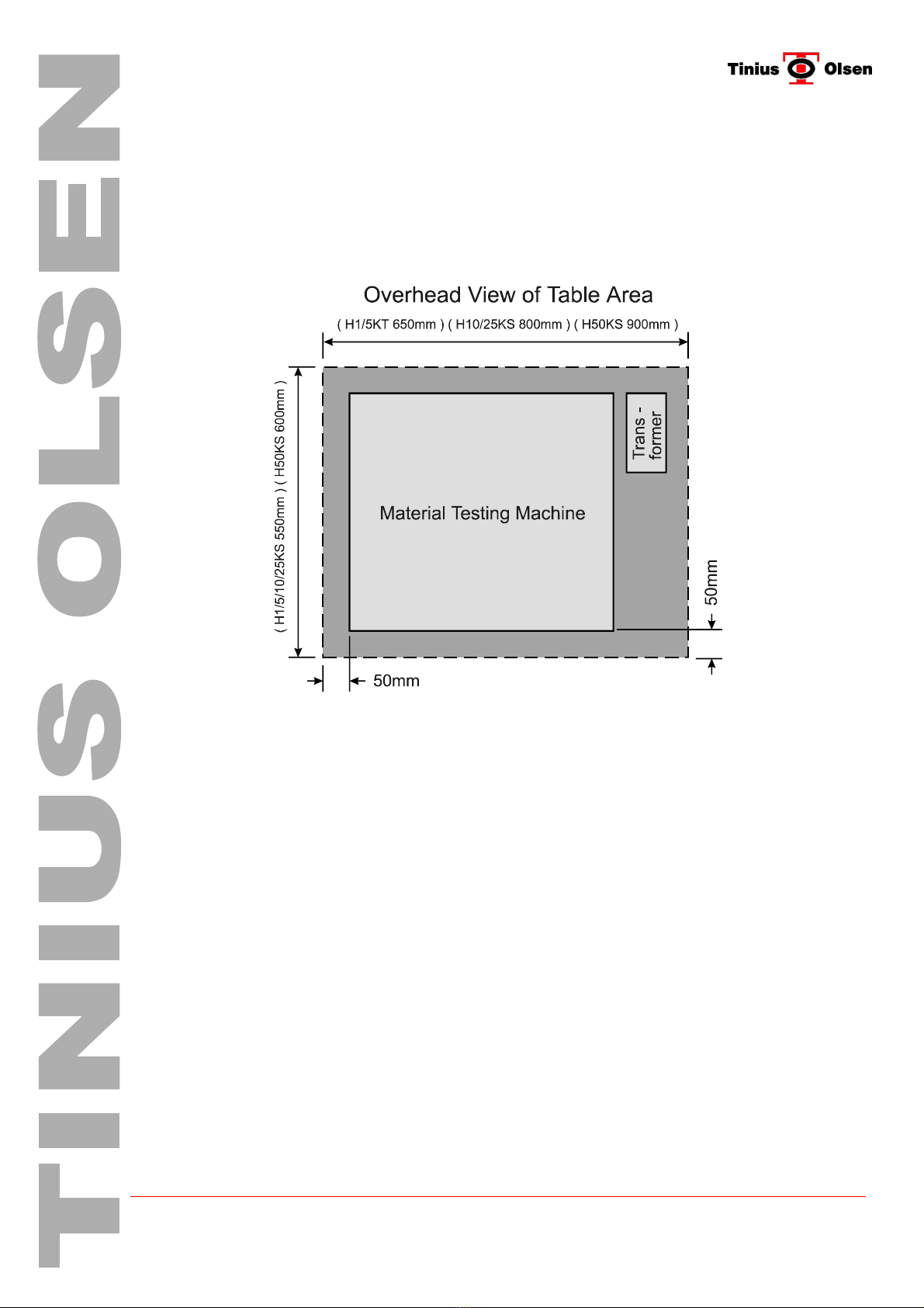
Place the machine on a sturdy bench ensuring that is capable of taking the following loads
(H1/5KL > 50kg), (H10/25KL > 117kg),(H50KL > 180kg). It is also important to make sure the
bench is level especially when using lower capacity load cells.
The diagram below outlines the required area for each machine.
5.2. Mains Supply
Place the external power transformer within reach of the of the machine. (shown in the above
diagram) The transformer voltage is indicated on the power transformer label and will require a
supply connector to be fitted. The supply cable must be connected as follows :-
Brown=Live , Blue=Neutral , Yellow/Green =Earth
NOTE External Power Transformer MUST BE EARTHED. Under no circumstance must the
machine be operated without an earth connection
Positioning of the machine and external power transformer should be arranged so that the
mains supply plug and socket are easily accessible. Under NO CIRCUMSTANCE must the
main supply plug and socket be OBSTRUCTED by any equipment. This is to allow
disconnection of the external power transformer in the event of an emergency.
© Tinius Olsen Ltd L-Series Manual – Issue 1 Page 16 of 31
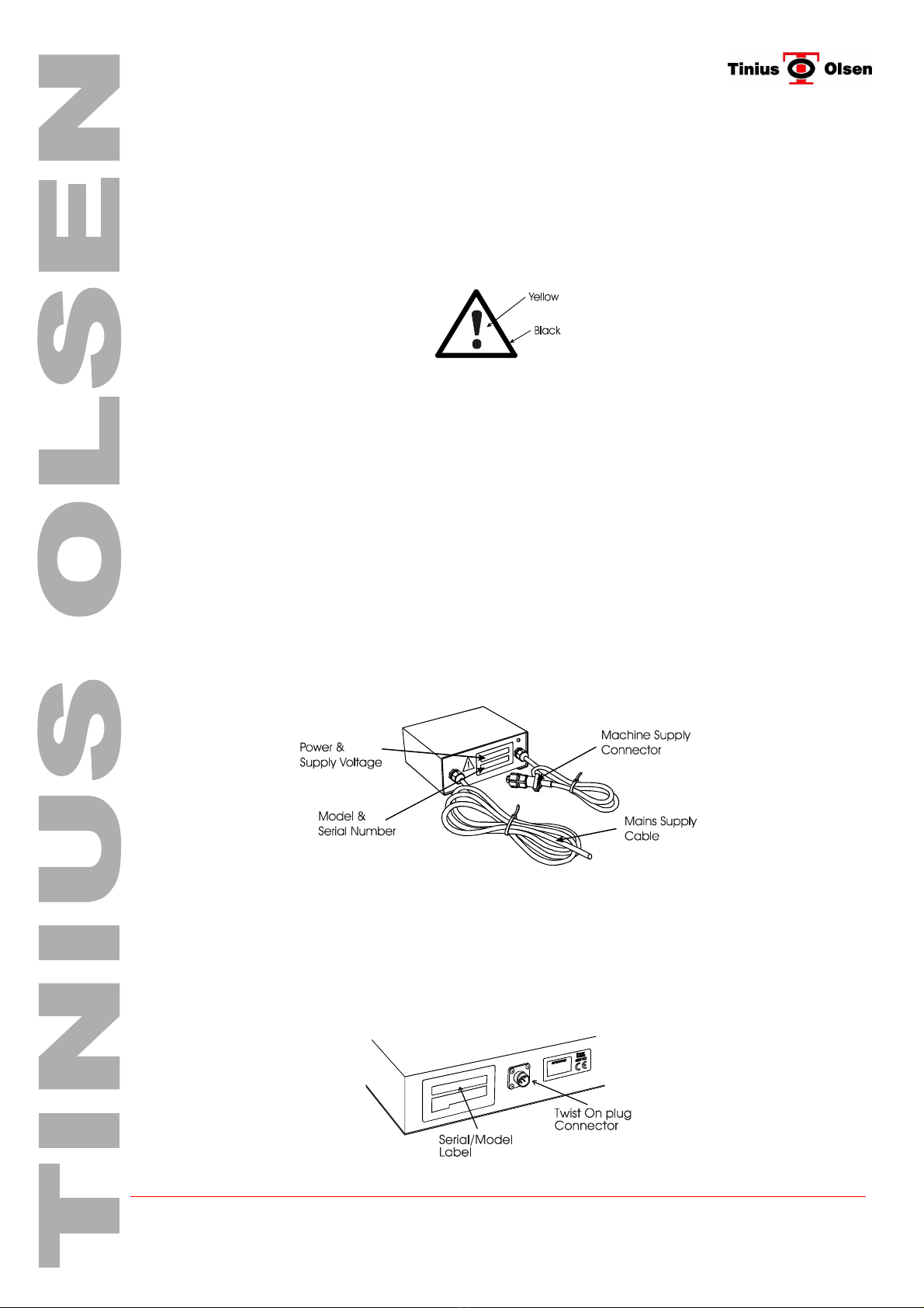
5.3. Warning Symbols
There are two warning symbols displayed on the L-Series machine. The purpose of these
symbols is to indicate a potential hazard and requires reference to the operating instructions.
5.3.1. Refer to Manual
The Refer to Manual Symbol is shown below
The warning symbol is located on the front left hand edge of the protective screen if
fitted. It indicates a hazard due to moving mechanical parts and the operator must refer
to the operating instructions when attempting to operate the machine. Additional
hazards may be present when carrying out sample testing and for this reason the
operator must ensure the protective screen be closed throughout the test
5.3.2. Power Transformer Hazardous Warning Symbol
The power transformer hazardous warning symbol is located on the front of the unit next
to the serial number/voltage/power label. It indicates that the unit is operating at a
HAZARDOUS VOLTAGE and the operator must refer to the operating instructions
regarding ‘Installation Environment’, ‘Operating Voltage’, ‘Connection’ and
‘Maintenance’.
Power and Voltage Ratings The diagram below shows where to locate the Power and
Voltage rating of the equipment. (H1/5KL 230V =+/- 10% 50/60Hz 330VA is) and
(H10/25KL and H50KL 230V =+/- 10% 50/60Hz 530VA) The mains supply cable and
machine supply connector are also indicated.
5.4. Connection to Supply
The connection of the power transformer to the machine is via a 4 pin twist on connector. The
following diagrams indicate how to connect the power transformer :-
Although these diagrams relate to the H5KL the method still applies to the 1/10/25/50KL)
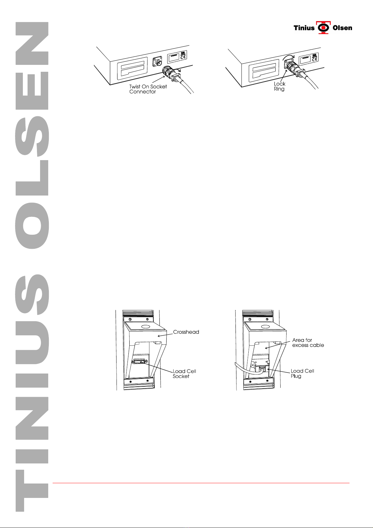
© Tinius Olsen Ltd L-Series Manual – Issue 1 Page 17 of 31
Rotate socket to align with plug then push to
engage lock ring Rotate lock ring clockwise to jack socket into
final position.
5.5. Fitting Load Cell
The machine will be provided with a load cell equal to or less than the maximum capacity of the
machine.
These interchangeable Load Cells are available in capacities from 50kN (11,250 lbf, 5100 kgf)
down to 5N (1.1 lbf, 0.5 kgf).
5.5.1. Single Screw Machines
On H1KL single screw machines, the load cell is mounted on the underside of the fixed
crosshead at the top of the loading column.
The H5KL requires the load cell to be mounted on the underside of the moving
crosshead, both machines use a hex bolt and washer for fixing. Lower capacity load
cells require a spacer sleeve to be inserted in the crosshead enabling smaller load cell
mounting bolts to be used (H5KL only). Use the hex key provided to tighten the cell in
place. Before mounting any load cells to the crosshead, always check to insure that the
contact surfaces are clean.
Connect the load cell by plugging the 15 pin connector into the load cell socket just
under the crosshead. Care must be taken when mounting the cell as it is handed. The
correct orientation is with the slot to the top and cable at the rear for single screw
machines
Note Failing to do so will effect the overall performance of the cell.
The following diagrams indicate how to mount a 5KN load cell to the H5KL Machine.
Ensure both areas are free of packing
and are clean Align plug with socket and push together
Store excess cable in area shown
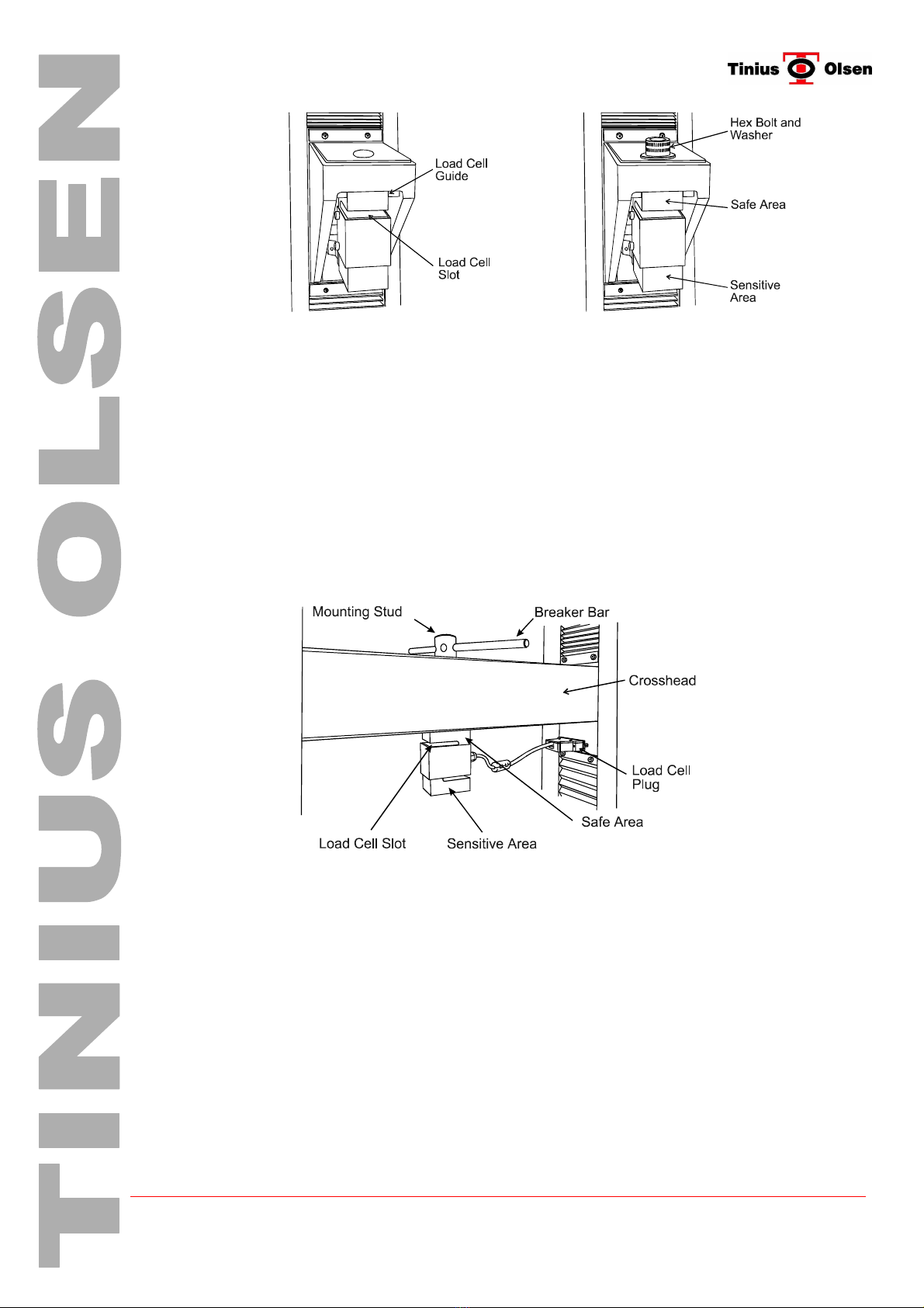
Hold load cell in safe area and position it parallel to the crosshead then fully tighten with
Hex Key. When installing low capacity load cells (less than 5kN) it is imperative the load
be held in the safe area when locking the load cell in position (shown in the diagram
below).
Failure to carry out the above procedure may lead to load cell damage beyond repair.
© Tinius Olsen Ltd L-Series Manual – Issue 1 Page 18 of 31
Align load cell to guides and mounting
hole with slot at top and facing out Fit hex bolt and washer , hold load cell in
safe area when tightening with Hex key
Note Load Cells other than 5kN rely on manual alignment with crosshead.
5.5.2. Twin Screw Machines
On the larger capacity twin screw machines, the load cells are mounted under the
moving crosshead with a mounting stud, and a breaker bar provided for tightening the
load cell in place. Again care must be taken when mounting the load cell as it is handed.
The correct orientation for twin screw machines is with the slot to the left and cable to
the right.
The diagram below indicates how to mount the load cell to a twin screw machine
(H10KL / H25KL / H50KL)
Align the load cell with the with mounting hole beneath the crosshead. Place the
mounting stud through crosshead and screw into load cell. Hold load cell in safe area
and position it parallel to the crosshead then fully tighten with breaker bar. Connect load
cell by plugging the 15 pin load cell plug connector into load cell socket located beneath
and to the right of the moving crosshead.
5.6. Connection to PC
Before attempting to connect the RS-232 Serial cable, ensure both Testing Machine and
PC computer are SWITCHED OFF
This connection allows the computer to communicate with the testing machine’s internal
electronics.
© Tinius Olsen Ltd L-Series Manual – Issue 1 Page 19 of 31
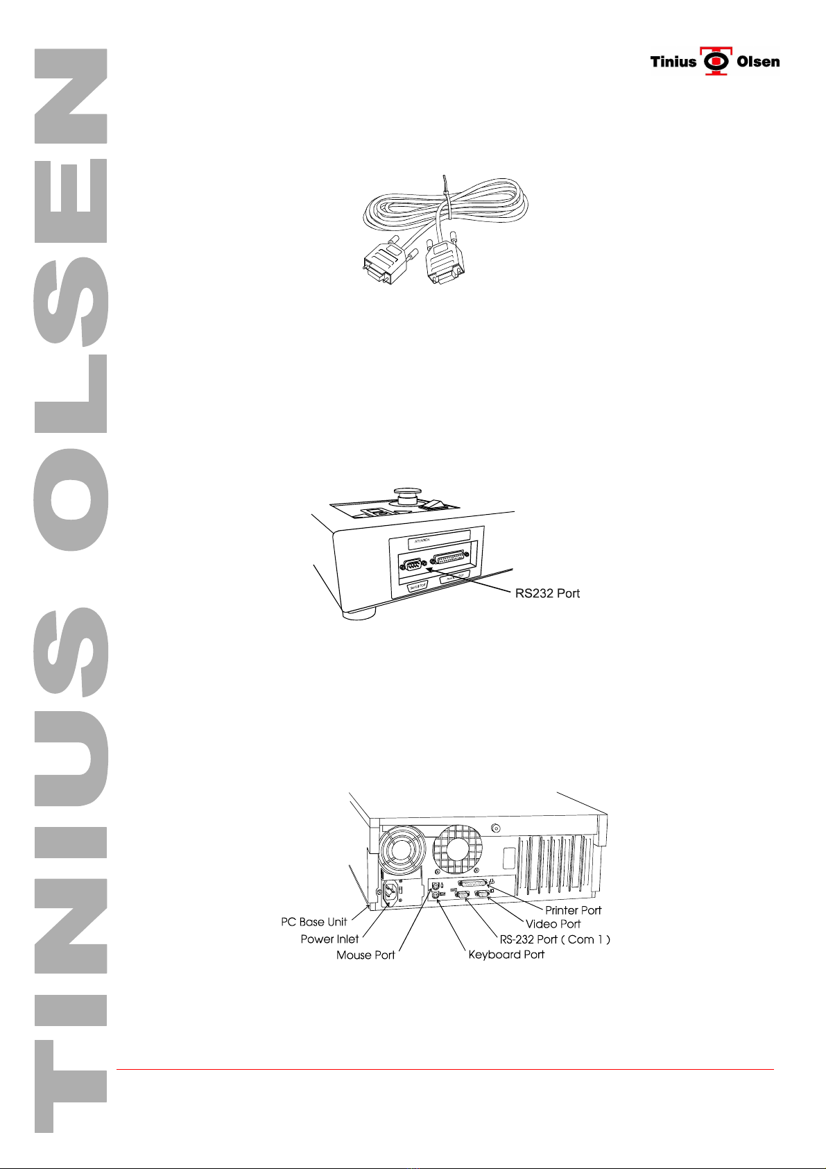
5.6.1. Lead
Connection from your “ PC “ to the Testing Machine is via a D type 9 way RS-232
socket to socket cable, as indicated below.
Note This cable is not a one to one cable, (some of the signals are reversed). For this
reason it should only be used for RS-232 machine to computer connection.
5.6.2. Machine Port
The RS-232 Port is located on the front, right hand side of the machine. Simply align
the 9 way D type cable socket connectors to its mating plug on the machine, taking care
not to bend any pins, whilst held in this position tighten the two socket jack screws until
the connector is fully engaged.
The diagram below indicates position of machine RS-232 Port.
The other end of the RS-232 serial cable connects to the PC Computer RS-232 Port
(Com 1) located at the rear of the PC Base Unit. The method is the same as used on
the machine by aligning the 9 way D-type connectors then tighten the two jack screws.
5.6.3. PC Port
The diagram below shows a rear view of a typical PC Base Unit. Care must be taken to
locate the RS-232 Port (Com 1) as many of the connectors look very similar.

© Tinius Olsen Ltd L-Series Manual – Issue 1 Page 20 of 31
6. Power ON Checks
Before Powering the machine on, check the following
6.1. Emergency Stop Switch
Before the machine can be turned ON it is necessary to check the position of the emergency
stop switch. The function of this switch is to STOP the machine as quickly as possible in the
case of an emergency. e.g.:- where the machine behaves in an unexpected manner, or when
there is a risk of injury to the operator. The emergency Stop switch should NOT be used as the
Machine OFF/ON switch.
6.1.1. Location
The emergency stop switch for the H1KL and H5KL is located on the front, top right
hand side of the machines base. Twin screw machines (H10/25 and 50KL) have the
emergency stop switch located on the top left hand side of the machine’s base.
The diagrams below indicate location of the emergency stop button
H1KL / H5KL Emergency and Power Switch
located on right hand side of machine H10KL / H25KL / H50KL Emergency and
Power Switch located on left hand side of
machine
6.1.2. Operation
To check if the emergency stop switch is in its normal position rotate the top part of the
switch clockwise (direction shown by arrows on top of switch). If the switch had been
previously activated, on rotation the top will spring upwards. If no upwards movement is
felt the switch is already in its normal position.
6.2. Power ON/OFF Switch.
6.2.1. Location
Power ON/OFF
Switch
Power ON/OFF
Switch
H1KL / H5KL Power Switch located on right
hand side of machine
H10KL / H25KL / H50KL Power Switch
located on left hand side of machine
Turn the machine ON with the power switch. The control panel STOP Switch LED will now
illuminate. If the direction/stop LEDS are blinking and the alarm beeping the EMERGENCY
STOP Switch is probably activated. Reset the emergency stop switch as described in the above
section, turn the machine OFF, allowing a few seconds before turning the back ON again.
This manual suits for next models
5
Table of contents
Popular Test Equipment manuals by other brands

Tektronix
Tektronix 507 instruction manual

Circuitlink
Circuitlink BrakeCheck 2 Series user manual

Besantek
Besantek BST-IT706 instruction manual

PCB Piezotronics
PCB Piezotronics 394A11 Installation and operating manual

Futura Apsol
Futura Apsol HAAP96 user manual

inTest
inTest THERMOSTREAM ATS-545 Interface & Applications manual


