Tinycontrol 6G10A User manual

MANUAL
IP Power Socket 6G10A v2

2
IP Power Socket 6G10A v2 – LANLIS-010, LANLIS-015
www.tinycontrol.eu
Notes on the safe use
It is essential to read the entire contents of the operating instructions and adhere to its
recommendations. The manufacturer is not responsible for the consequences of not ap-
plying the recommendations of this manual and use the power socket inconsistent with
its intended purpose. The product should be kept away from children.
Do not connect a power strip to the sockets without the correct installation
against electric shock (without contact (pin) protective!)
Prior to using a power strip:
tBefore using a power strip, check its technical condition - it is prohibited to use a power
strip in which any part is damaged - PRESENT DANGER OF ELECTRIC SHOCK / OF FIRE.
tBefore connecting the device / devices into a power strip, make sure the maximum total
current consumption in watts (W) equipment / devices that want to simultaneously con-
nect to a power strip. The total power of the connected device / devices to be connected
should not exceed that specied for the power strip.
tPower strip technical data - including above all permissible current rating and maximum
permissible load located on the housing. Technical data can also be seen on the packa-
ging or in the data sheet (available at: www.ledats.pl, www.tinycontrol.eu or www.wire-
lesslan.pl).
t Before connecting the power strip to the mains or before connecting to a power strip,
make sure the connected device is turned o.
tBefore starting work, the power cord should be fully developed.
Replacing the fuse link:
1. Remove the power strip from the mains.
2. Remove cap of fuse housing and remove the faulty cartridge fuse.
3. Install a new cartridge fuse type: 5x20 mm WTA 10A 250V.
4. Screw cap with insert into the socket.
5. Connect the power strip to the mains.
NOTE: defective fuse CAN NOT BE REPAIRED. Replace it with a an ecient.
Restrictions:
tIt is forbidden to have any independent disassemble, modify, adapt or repair a power
strip or its components, in case repairs are necessary - please contact an authorized
service center.
tIt is forbidden to remove and / or bridging and / or any interference with any components
of power strip, including primarily switches, earthing pins, thermal protection, overload
protection.
NOTE: To reduce the risk of electric shock or re, do not remove the cover. Service
work can only be carried out by qualied personnel. Repairs have a qualied service
personnel using only original parts. Only this guarantees that the safety equipment
is maintained.

IP Power Socket 6G10A v2 – LANLIS-010, LANLIS-015
3
www.tinycontrol.eu
IP Power Socket 6G10A v2
Power distribution unit in Rack 19” standard. Equipped with six independently managed
outlets for 230V. Management available by embeded web server or SNMP protocol. Except
ethernet socket ther is 1wire socket for temperature measurement.
RESTARTER, MONITOR, WATCHDOG, CONTROLLER
FEATURES:
tWWW or SNMP v2 management.
trmware upgrade by special application
tread data in real time without refresh the page
tON/OFF power to all outlets directly from a web page or SNMP (IP/outs.cgi?outx=x)
tEven Cong - adjustable power ON dealy on each outlet after turnign on the unit
tSheduler - set up to 10 time events like turning on, o, resets
tWatchdog IP for 6 IP adresses and automatical reaction if no reply
tRemote - availability to remote control from buttons of other Lan Controller
tmonitoring up to 4 temperature sensors on 1wire interface
tenvironment temperature measure in power unit
temail or SNMP alert when Watchdog activation or temperature sensor lled condition
tdate and time from NTP or manual
te-mail notication about programmed events
tSNMP TRAP notication about programmed events
tAutomatic send SNMP TRAP with state or value inputs
timplement protocols: HTTP, SNMP, SMTP, SNTP, ICMP, DNS, DHCP.
tservice temperature sensors: DS18B20
Default user and password is„admin”, IP adress is 192.168.1.100
TECHNICAL SPECIFICATIONS
toutlet quantity: 6
tpower voltage: AC 230V
tmax curent: 10A (total of all outlets)
tmax power: 2300W
tfuse: 2x10A
tpower cable: wire with plug
tethernet: RJ45, 10Mb
t1wire: RJ11 support up to 4 sensors

4
IP Power Socket 6G10A v2 – LANLIS-010, LANLIS-015
www.tinycontrol.eu
Change outputs
state display
Management by WWW.
1. Control Panel
Any text description,
max 8 chars
Reset time – for 0 normal
outputs work (ON/OFF) ,
for time > 0 output after
push button change state
and return to state before
after the specied time in
seconds (max 65534).
click cause
change relay
state on opposite
(OUT0 relay on
board)
automatic socket arming
at xed time
(two panes: one - time
arming, second - break
time)
Set State
All output
simultaneously
according to
combo box

IP Power Socket 6G10A v2 – LANLIS-010, LANLIS-015
5
www.tinycontrol.eu
Delay of set outputs
after occur events,
in seconds max 65535
2. Events Cong
Connection time slot
when starting terminal.
Prevents inclusion all
sockets at the same time.
Automatic application
of the socket after starting
terminal
Email text taht
will be send if
events occurance,
max amount char
is 79. Chars „=”
and „&” are not
allowed
The hysteresis
value for
a given input.
Save setings
(ON/OFF
input
you don’t
must save)
inclusion
of an input
The value of the
input beyond
the upwards the
the socket will be
activated, send an
e-mail or SNMP
Trap
The value of the
input, after
crossing down that
slot will be
activated, send an
e-mail or SNMP
Trap

6
IP Power Socket 6G10A v2 – LANLIS-010, LANLIS-015
www.tinycontrol.eu
Functional Description Event Table
With this change, you can exibly dene thresholds and intervals in which such slot is to
be enabled / disabled.
If you have the proper checks the condition of a number of sensors is to force the state to
be the sockets that was last registered event.
3. Watchdog
Time to respond is 4 second, after this time
one PING failures is counting. In time wa-
iting to respond, another IPX aren’t send
ping, this may causa stretch time statment
that another IPX adress is inaccessible.
Selecting this option forces the watchdog
owhen in the Event Table occur o/ on
the socket.
Upon his return to the previous state out-
put watchdog is started automatically.
(max 65535s).
Amount PING failures, after
this one of three events will be
happen: set (ON) output, set
(OFF) output reset (ON/OFF)
output on denite time (max
65535s).

IP Power Socket 6G10A v2 – LANLIS-010, LANLIS-015
7
www.tinycontrol.eu
4. Scheduler
Format: number output (from 0 to 5),day1,day2,day3,day4,day5,day6, xx:xx:xx(time)
Week Day: Mo - Monday, Tu- Tuesday, We - Wednesday, Th - Thursday, Fi - Friday, Sa - Sa-
turday, Su - Sunday, ## - all week day. Letter size is important.
Example:
0,Mo,12:23:00 - sets out0 every Monday at 12:23:00
1,Sa,Fr,Mo,23:22:03 - sets out1 every Saturday, Friday and Monday at 23:22:03
1,Sa,Fr,Mo,Tu,Su,Th,23:22:03 - sets out1 every Saturday, Friday, Monday, Tuesday, Sunday
and Thursday at 23:22:03
0,##,12:01:30 - sets out0 every week day at 12:01:30
The eect of this may be the inclusion of a relay, switched oor reset (turn on and o) for
a limited period in seconds. (max 65535).

8
IP Power Socket 6G10A v2 – LANLIS-010, LANLIS-015
www.tinycontrol.eu
5. Network Conguration
e-mail client set-
tings parameter.
After changing the
settings in order to
test the customer -
should be save your
settings - the „Save
Cong” button.
The user name and
password to access
the module.
You can disable
authorization.
admin (default)

IP Power Socket 6G10A v2 – LANLIS-010, LANLIS-015
9
www.tinycontrol.eu
NTP server settings.
Time Interval - the
interval in minutes
between synchroni-
zations.
Fields community
(password) for SNMP,
must be the same in
your queries in order
to LK replied.
TRAP Enable
– enabled send
TRAP by SNMP.
Enable Automatic
Send TRAP – enable
automatic send TRAP
by SNMP (above
TRAP Enable must be
enable)
Time is set individually
or with an NTP server.
When set manually
each time you reboot
the machine need to
set the time.
Remote Control - working as a server (receiving packets and enable / disable the cor-
responding socket). Terminal working as a server can be triggered from any number of
clients (Lan Controllers), the condition is set to the same password.
Time Interval (max
value 10555) – period
to send TRAP from
given INPUT, accura-
cy 10 s

10
IP Power Socket 6G10A v2 – LANLIS-010, LANLIS-015
www.tinycontrol.eu
Reading XML data
Enter the IP address and the page name eg 192.168.1.100/st0.xml
The values of the sensors should be divided by 10
Control Panel:
- Dynamic data - st0.xml
- Static data - st2.xml
Events Cong: s.xml
Watchdog: w.xml
Scheduler: sch.xml
Network Cong: board.xml
Working time: s_time.xml using the Timezone
Switching sockets http request
You can arm / switch set out without clicking on the buttons in the control panel, making
use of the following commands:
IP / outs.cgi ? out = xxxxx - switches set the output to the opposite of the current
IP / outs.cgi ? outx = x - disable or enable a specic output
when password authentication is enabled , the command of the following form:
user : password @ IP / outs.cgi ? out = xxxxx
user : password @ IP / outs.cgi ? outx = x
Examples:
192.168.1.100/outs.cgi ? out = 0 - changes the output state to the opposite out0
192.168.1.100/outs.cgi ? out = 2 - out2 output changes state to the opposite
192.168.1.100/outs.cgi ? out = 02 - changes the output state out0 and out2
to the opposite
192.168.1.100/outs.cgi ? out = 012345 - changes the state of the outputs of out0 to out5
the opposite
192.168.1.100/outs.cgi ? out0 = 0 - turns out out0 ( ON state )
192.168.1.100/outs.cgi ? out0 = 1 - turns out out0 ( OFF )
192.168.1.100/outs.cgi ? out1 = 0 - turns out out1 ( ON state )
192.168.1.100/outs.cgi ? out1 = 1 - turns out out1 ( OFF )
192.168.1.100/outs.cgi ? out4 = 0 - turns out out4 ( ON state )
192.168.1.100/outs.cgi ? out4 = 1 - turns out out4 ( OFF )

IP Power Socket 6G10A v2 – LANLIS-010, LANLIS-015
11
www.tinycontrol.eu
Firmware Upgrade
In the event that there is a new version of the software or special version for application,
it is possible to load such software to the device. This can be done remotely over the ne-
twork using TFTP.
You my upgrade rmware on two way:
1. By dedicate software „LAN Controler Tools” (nd controler or put IP and click „Upgrade
Firmware”).
2. By any TFTP client, description below.
Send rmware le by TFTP, you have 5 second (Green LED on RJ45 socket blink) to start
send rmware when modul run after reset (you my casus reset by click button „Save con-
g and Reboot” in Network conguration or „Reset” button on board or dedicate softwa-
re „LAN Controler Tools”). If start transmision not happen that device start work normal.
If tftp transmision will start than wait about 90 second to nish upload rmware. After
upload device will be reset and start normal. If you want to upload upgrade le chose
„Save cong and Reboot” in Network conguration or power OFF and power ON device .
The le must be send in binary mode eg. In Windows XP tftp client
tftp –i 192.168.1.100 put „le_upgrade.bin”.
After successful loading, the device will reboot and will be ready to go.
If you try to send the wrong le get an error message „invalid le”

12
IP Power Socket 6G10A v2 – LANLIS-010, LANLIS-015
www.tinycontrol.eu
NUMBERS OID for SNMP
Contents of the instructions is regularly checked and if necessary corrected. If the observations errors or
inaccuracies, please contact us. It can not be ruled out that, despite best eorts, however, some discrepancies
arose. To get the latest version, please contact us or distributors.
© Konsorcjum ATS Sp.J.
Copying, duplication, reproduction whole or in part
without the consent of the owner is prohibited.
Konsorcjum ATS Sp.J.
ul. Żeromskiego 75, 26–600 Radom, POLAND
tel./fax: 48 366 00 30, e-mail: sales@ledats.pl
www.tinycontrol.eu, www.ledats.pl, www.wirelesslan.pl, www.ats.pl
Soft_version .1.3.6.1.2.1.1.1.0 READWRITE ASCII_STRING
SYS_OID .1.3.6.1.2.1.1.2.0 READONLY OID
SYS_UP_TIME .1.3.6.1.2.1.1.3.0 READONLY TIME_TICKS.
LAN_NAME .1.3.6.1.2.1.1.5.0 READWRITE ASCII_STRING.
TRAP_RECEIVER_ID .1.3.6.1.4.1.17095.2.1.1.1.1 READWRITE BYTE.
TRAP_RECEIVER_ENABLED .1.3.6.1.4.1.17095.2.1.1.2.1 READWRITE BYTE.
TRAP_RECEIVER_IP .1.3.6.1.4.1.17095.2.1.1.3.1 READWRITE IP_ADDRESS.
TRAP_COMMUNITY .1.3.6.1.4.1.17095.2.1.1.4.1 READWRITE ASCII_STRING.
OUT0 (5) .1.3.6.1.4.1.17095.3.1.0 READWRITE BYTE.
OUT1 (6) .1.3.6.1.4.1.17095.3.2.0 READWRITE BYTE.
OUT2 (7) .1.3.6.1.4.1.17095.3.3.0 READWRITE BYTE.
OUT3 (8) .1.3.6.1.4.1.17095.3.4.0 READWRITE BYTE.
OUT4 (9) .1.3.6.1.4.1.17095.3.5.0 READWRITE BYTE.
OUT5 (10) .1.3.6.1.4.1.17095.3.6.0 READWRITE BYTE.
TEMP (11) .1.3.6.1.4.1.17095.3.7.0 READONLY ASCII_STRING.
VCC (16) .1.3.6.1.4.1.17095.3.8.0 READONLY ASCII_STRING.
INP1 (12) .1.3.6.1.4.1.17095.3.9.0 READONLY ASCII_STRING.
INP2 (13) .1.3.6.1.4.1.17095.3.10.0 READONLY ASCII_STRING.
INP3 (14) .1.3.6.1.4.1.17095.3.11.0 READONLY ASCII_STRING.
INP4 (15) .1.3.6.1.4.1.17095.3.12.0 READONLY ASCII_STRING.
This manual suits for next models
2
Table of contents
Popular Power Strip manuals by other brands
Tripp Lite
Tripp Lite 4SPDX Specifications

LIVARNO LUX
LIVARNO LUX 306794 Operation and safety notes

Tripp Lite
Tripp Lite UL17CB-15 specification
Workrite
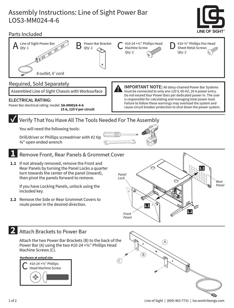
Workrite Line of Sight LOS3-MM024-4-6 Assembly instructions

Tripp Lite
Tripp Lite PS7224-20T Specification sheet

Tripp Lite
Tripp Lite TLM615NCRA Specification sheet
