TIP TIG ALLINONE User manual
.
TIP TIG - ALLINONE
Operating Manual
Version 1.5 Revision 0
TIP TIG – ALL IN ONE
OPERATING MANUAL

TIP TIG - ALLINONE, OPERATING MANUAL
Page 2 of 57
INTRODUCTION
Thank you for the trust you have placed in our company and congratulations on buying this high-
quality TIP TIG product. These instructions will help you familiarize yourself with the product. Reading
the instructions carefully will enable you to learn about the many different features it has to offer. This
will allow you to make full use of its advantages.
Please also note the safety rules to ensure greater safety when using the product. Careful handling
of the product will repay you with years of safe and reliable operation. These are essential
prerequisites for excellent results.

TIP TIG - ALLINONE, OPERATING MANUAL
Page 3 of 57
CONTENTS
1. GENERAL INSTRUCTIONS 5
2. INTENDED USE 6
2.1 Declaration of conformity 6
2.2 Welding in environments with increased electrical hazards 6
2.3 Calibration/Validation 6
3. SAFETY RULES 7
3.1 Explanation of safety symbols 7
3.2 General safety instructions 7
4. GENERAL 10
4.1 Device concept 10
4.2 Power sources 10
4.3 Crane transport 11
5. CONTROLS, CONNECTIONS AND MECHANICAL COMPONENTS 12
5.1 System overview 12
5.2 Front connection 15
5.3 Rear connection 16
5.4 Main power switch with fuses 17
5.5 Hotwire amperage adjustment 17
5.6 Control panel – D24B2M1.6 18
5.7 Control panel – Version 2.0 20
6. INSTALLATION AND COMMISSIONING 24
6.1 Before installation and commissioning 24
6.2 Connecting the interconnection hose package, welding torches and workpiece
lead 25
6.3 Inserting/replacing feed rollers 29
6.4 Inserting the wires pool 29
6.5 Inching the wire electrode 30
6.6 Spool brake setting 32
7. START-UP 33
8. TROUBLESHOOTING, MAINTENANCE AND DISPOSAL 34
8.1 Troubleshooting 34
8.2 Care, maintenance and disposal 42
9. TECHNICAL DATA 43
10. APPENDIX 45
10.1 Spare part list 45

TIP TIG - ALLINONE, OPERATING MANUAL
Page 4 of 57
10.2 Wire Feed Speed 51
10.3 Wiring diagram 55

TIP TIG - ALLINONE, OPERATING MANUAL
Page 5 of 57
1. GENERAL INSTRUCTIONS
In the event of queries on installation, commissioning, operation or special conditions at the
installation site, or on usage, please contact your sales partner or our customer service
A list of authorized sales partners can be found at www.tiptig.com.
Liability relating to the operation of this equipment is restricted solely to the function of the equipment.
No other form of liability, regardless of type, shall be accepted. This exclusion of liability shall be
deemed accepted by the user on commissioning the equipment.
The manufacturer is unable to monitor whether or not these instructions or the conditions and
methods are observed during installation, operation, usage and maintenance of the equipment.
An incorrectly performed installation can result in material damage and injure persons as a result.
For this reason, we do not accept any responsibility or liability for losses, damages or costs arising
from incorrect installation, improper operation or incorrect usage and maintenance or any actions
connected to this in any way.
© TIP TIG Automation GmbH, Baumayrweg 5, 4631 Krenglbach, Austria
The copyright to this document remains the property of the manufacturer. Reprinting, including
extracts, only permitted with written approval.
The content of this document has been prepared and reviewed with all reasonable care. The
information provided is subject to change, errors excepted.
CAUTION
Read the operating instructions!
The operating instructions provide an introduction to the safe use of the products.
• Read the operating instructions for all system components!
• Observe accident prevention regulations!
• Observe all local regulations!
• Confirm with a signature where appropriate.

TIP TIG - ALLINONE, OPERATING MANUAL
Page 6 of 57
2. INTENDED USE
2.1 Declaration of conformity
The labelled machine complies with the following EC directives and standards in
terms of its design and construction:
• 2014/35/EU Low Voltage Directive (LVD)
• 2014/30/EU Electromagnetic Compatibility Directive (EMC)
• 2011/65/EU Restriction of Hazardous Substance (RoHS)
Standards
• IEC 60974-1: 2012 Arc welding equipment - Part 1: Welding power sources
• IEC 60974-3: 2013 Arc welding equipment - Part 3: Arc striking stabilizing
devices
• IEC 60974-10: 2014 Arc welding equipment – Part 10: Electromagnetic
compatibiliy requirements
August 1, 2018
______________________________ ______________________________
Jürgen Plasch, CEO Date of Declaration
In case of unauthorised changes, improper repairs, and/or prohibited modifications which have not
been explicitly authorised by TIP TIG Automation GmbH, this declaration shall be voided.
2.2 Welding in environments with increased electrical hazards
In compliance with IEC / DIN EN 60974, VDE 0544 the machines can be used in
environments with an increased electrical hazard.
2.3 Calibration/Validation
We hereby confirm that this machine has been tested using calibrated measuring equipment, as
stipulated in IEC/EN 60974, ISO/EN 17662, EN 50504, and complies with the admissible tolerances.
Recommended calibration interval: 12 months
2
Konformitätserklärung
TIP TIG Automation GmbH
Erklärt, dass die Schweißautomatisation:
TIP TIG - Automation
den folgenden Richtlinien entspricht:
2014/35/EU, 2014/30/EU
und in Übereinstimmung mit den folgenden
Normen hergestellt wurde:
EN 60974-1:2012, EN 60974-3:2014,
EN 60974-10:2014
14.02.2018
Jürgen Plasch
TIP TIG Automation GmbH., Baumayrweg 5, 4631 Krenglbach, Austria
WARNING!
Hazards due to improper usage!
The machine has been constructed to the state of the art and any regulations and
standards applicable for use in industry and trade. It may only be used for the welding
procedures indicated at the rating plate. Hazards may arise for persons, animals and
material objects if the equipment is not used correctly. No liability is accepted for any
damages arising from improper usage!
• The equipment must only be used in line with its designated purpose and by trained or
expert personnel!
• Do not improperly modify or convert the equipment!
Intended use
Applications
8 099-000180-EW501
27.06.2017
3 Intended use
WARNING
Hazards due to improper usage!
The machine has been constructed to the state of the art and any regulations and
standards applicable for use in industry and trade. It may only be used for the welding
procedures indicated at the rating plate. Hazards may arise for persons, animals and
material objects if the equipment is not used correctly. No liability is accepted for any
damages arising from improper usage!
•The equipment must only be used in line with its designated purpose and by trained or
expert personnel!
•Do not improperly modify or convert the equipment!
3.1 Applications
Wire feeder to feed welding consumables for MMA welding.
3.1.1 Use and operation solely with the following machines
A suitable power source (system component) is required in order to operate the wire feed unit!
This machine can be combined with any TIG welding machine.
3.2 Documents which also apply
3.2.1 Warranty
For more information refer to the "Warranty registration" brochure supplied and our information
regarding warranty, maintenance and testing at www.ewm-group.com!
3.2.2 Declaration of Conformity
The labelled machine complies with the following EC directives in terms of its design and
construction:
•Low Voltage Directive (LVD)
•Electromagnetic Compatibility Directive (EMC)
•Restriction of Hazardous Substance (RoHS)
In case of unauthorised changes, improper repairs, non-compliance with specified deadlines for "Arc
Welding Equipment –Inspection and Testing during Operation", and/or prohibited modifications which
have not been explicitly authorised by EWM, this declaration shall be voided. An original document of the
specific declaration of conformity is included with every product.
3.2.3 Welding in environments with increased electrical hazards
In compliance with IEC / DIN EN 60974, VDE 0544 the machines can be used in
environments with an increased electrical hazard.
3.2.4 Service documents (spare parts and circuit diagrams)
WARNING
Do not carry out any unauthorised repairs or modifications!
To avoid injury and equipment damage, the unit must only be repaired or modified by
specialist, skilled persons!
The warranty becomes null and void in the event of unauthorised interference.
•Appoint only skilled persons for repair work (trained service personnel)!
Original copies of the circuit diagrams are enclosed with the unit.
Spare parts can be obtained from the relevant authorised dealer.
3.2.5 Calibration/Validation
We hereby confirm that this machine has been tested using calibrated measuring equipment, as
stipulated in IEC/EN 60974, ISO/EN 17662, EN 50504, and complies with the admissible tolerances.
Recommended calibration interval: 12 months
TIP TIG - ALLINONE, OPERATING MANUAL
Page 7 of 57
3. SAFETY RULES
3.1 Explanation of safety symbols
NOTE! Indicates a risk of flowed and possible damage to the equipment.
IMPORTANT! Indicates tips for correct operation and other particularly useful information. It does
not indicate a potential damaging or dangerous situation.
If you see any of the symbols depicted in the “Safety rules” chapter, special care is required.
3.2 General safety instructions
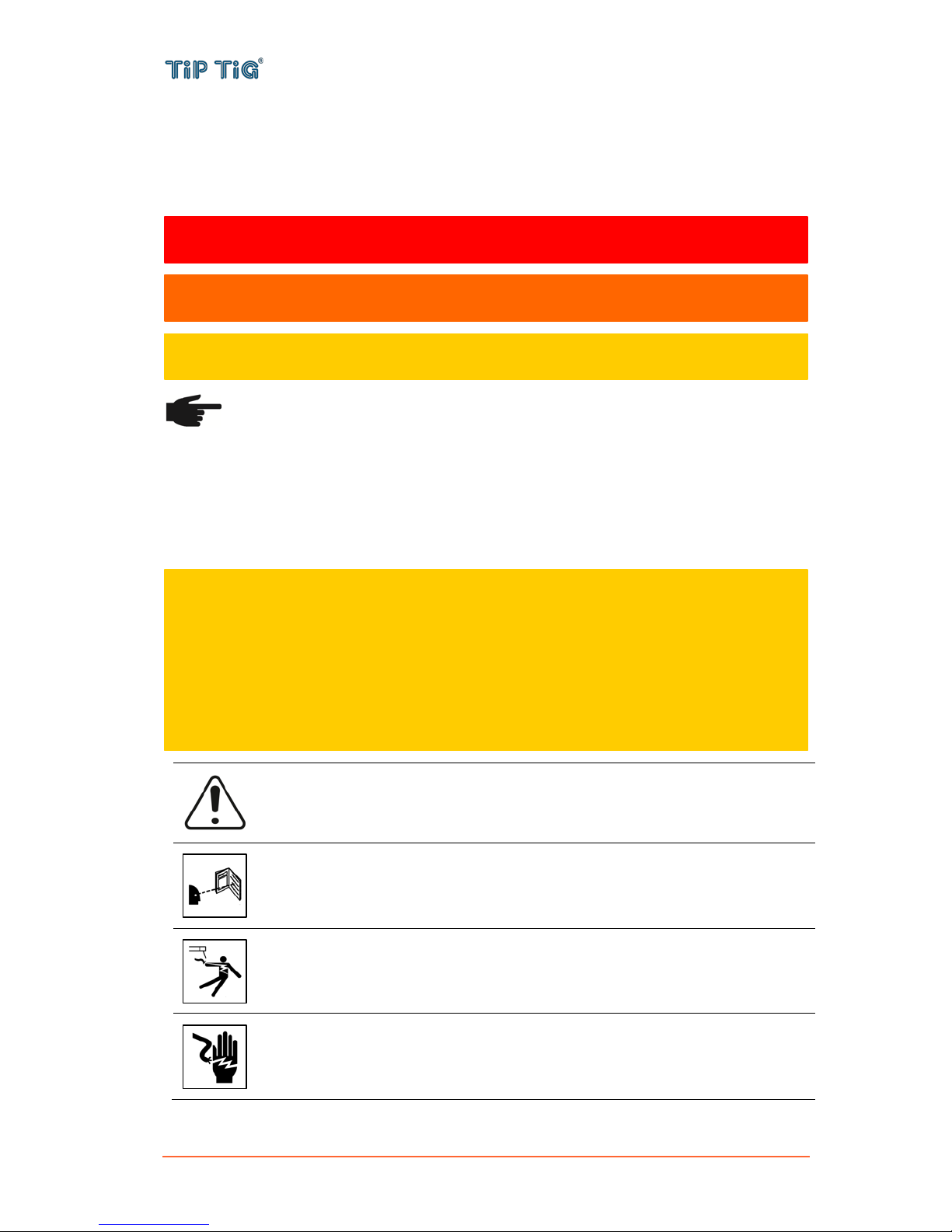
WARNING: This symbol indicates that instructions must be followed to avoid
serious personal injury, loss of life, or damage to this equipment. Protect yourself
and others from possible serious injury or death.
READ AND UNDERSTAND INSTRUCTIONS: Read and understand this manual
before operating this equipment. Arc welding can be hazardous. Failure to follow
the instructions in this manual could cause serious personal injury, loss of life, or
damage to this equipment.
ELECTRIC SHOCK CAN KILL: Welding equipment generates high voltages. Do
not touch the electrode, work clamp, or connected work pieces when this equipment
is on. Insulate yourself from the electrode, work clamp, and connected work pieces.
ELECTRICALLY POWERED EQUIPMENT: Turn off input power using the
disconnect switch at the fuse box before working on this equipment. Ground this
equipment in accordance with local electrical regulations.
DANGER! Indicates immediate and real danger. If is not avoided, death or serious
injury will result.
WARNING! Indicates a potentially situation. Death or serious injury may result if
appropriate precautions are not taken.
CAUTION! Indicates a situation where damage or injury could occur. If it is not avoided,
minor injury and/or damage to property may result.
CAUTION
This equipment must be used by qualified personnel. Be sure that all installation, operation,
maintenance and repair procedures are performed only by qualified person. Read and
understand this manual before operating this equipment. Failure to follow the instructions in this
manual could cause serious personal injury, loss of life, or damage to this equipment. Read and
understand the following explanations of the warning symbols. TIP TIG is not responsible for
damages caused by improper installation, improper care or abnormal operation.
TIP TIG - ALLINONE, OPERATING MANUAL
Page 8 of 57
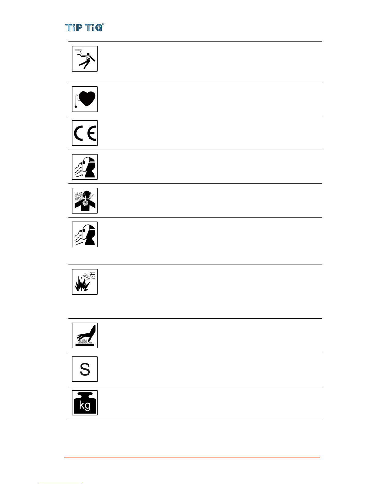
ELECTRICALLY POWERED EQUIPMENT: Regularly inspect the input, electrode,
and work clamp cables. If any insulation damage exists replace the cable
immediately. Do not place the electrode holder directly on the welding table or any
other surface in contact with the work clamp to avoid the risk of accidental arc
ignition.
ELECTRIC AND MAGNETIC FIELDS MAY BE DANGEROUS: Electric current
flowing through any conductor creates electric and magnetic fields (EMF). EMF
fields may interfere with some pacemakers, and welders having a pacemaker shall
consult their physician before operating this equipment.
CE COMPLIANCE: This equipment complies with the European Community
Directives.
ARTIFICIAL OPTICAL RADIATION: According with the requirements in
2006/25/EC Directive and EN 12198 Standard, the equipment is a category 2. It
makes mandatory the adoption of Personal Protective Equipment (PPE) having filter
with a protection degree up to a maximum of 15, as required by EN169 Standard.
FUMES AND GASES CAN BE DANGEROUS: Welding may produce fumes and
gases hazardous to health. Avoid breathing these fumes and gases. To avoid these
dangers the operator must use enough ventilation or exhaust to keep fumes and
gases away from the breathing zone.
ARC RAYS CAN BURN: Use a shield with the proper filter and cover plates to
protect your eyes from sparks and the rays of the arc when welding or observing.
Use suitable clothing made from durable flame-resistant material to protect you skin
and that of your helpers. Protect other nearby personnel with suitable, non-
flammable screening and warn them not to watch the arc nor expose themselves to
the arc.
WELDING SPARKS CAN CAUSE FIRE OR EXPLOSION: Remove fire hazards
from the welding area and have a fire extinguisher readily available. Welding sparks
and hot materials from the welding process can easily go through small cracks and
openings to adjacent areas. Do not weld on any tanks, drums, containers, or
material until the proper steps have been taken to insure that no flammable or toxic
vapors will be present. Never operate this equipment when flammable gases,
vapors or liquid combustibles are present.
WELDED MATERIALS CAN BURN: Welding generates a large amount of heat.
Hot surfaces and materials in work area can cause serious burns. Use gloves and
pliers when touching or moving materials in the work area.
SAFETY MARK: This equipment is suitable for supplying power for welding
operations carried out in an environment with increased hazard of electric shock.
EQUIPMENT WEIGHT OVER 30kg: Move this equipment with care and with the
help of another person. Lifting may be dangerous for your physical health.

TIP TIG - ALLINONE, OPERATING MANUAL
Page 9 of 57
CYLINDER MAY EXPLODE IF DAMAGED: Use only compressed gas cylinders
containing the correct shielding gas for the process used and properly operating
regulators designed for the gas and pressure used. Always keep cylinders in an
upright position securely chained to a fixed support. Do not move or transport gas
cylinders with the protection cap removed. Do not allow the electrode, electrode
holder, work clamp or any other electrically live part to touch a gas cylinder. Gas
cylinders must be located away from areas where they may be subjected to
physical damage or the welding process including sparks and heat sources.
CAUTION: The high frequency used for contact-free ignition with TIG (GTAW)
welding, can interfere with the operation of insufficiently shielded computer
equipment, EDP centers and industrial robots, even causing complete system
breakdown. TIG (GTAW) welding may interfere with electronic telephone networks
and with radio and TV reception.
NOISE APPEARES DURING WELDING CAN BE HARMFUL: Welding arc can
cause noise with high level of 85dB for 8-hour week day. Welders operating welding
machines are obligated to wear the proper ear protectors /appendix No. 2 for the
Decree of the Secretary of Labor and Social Policy from 17.06 1998 – Dz.U. No. 79
pos. 513/. According to the Decree the Secretary of Health and Social Welfare from
09.07.1996 /Dz.U. No. 68 pos. 194/, employers are obligated to carry examinations
and measurements of health harmful factors.
The manufacturer reserves the right to make changes and/or improvements in design without
upgrade at the same time the operator’s manual.

TIP TIG - ALLINONE, OPERATING MANUAL
Page 10 of 57
4. GENERAL
4.1 Device concept
The TIP TIG – AllinOne wire feeder is
contained in a metal housing and is suitable
for wire spools with max. diameter of 300 mm
(11.81 in.).
The 4-roller drive has good wire-feeding
properties. The wire feeder is also suitable for
long hose packages.
4.2 Power sources
The TIP TIG – AllinOne wire feeder can be used with many power sources available on the market
– See Table 3-1: Power supply compatibility. Preferably TIP TIG – AllinOne is used in combination
with the specially designed power source TIP TIG – TIG 350, 350 AC, 500, 500 AC.
Table 3-1: Power supply compatibility
Company
Model
Miller Electric
Maxstar 280DX, 350, 400, 700, 800
Dynasty 280DX, 350, 400, 700, 800
Dimensions MP 452, 650, 652
XMT MP 304, 350, 450
MP PipeWorks / PipeWorks Field Pro
Lincoln Electric
Aspect 375
Precision TIG 225, 275, 375
Invertec V311, V350Pro
Flextec 350X MP
Powerwave S350, S500 MP
Fronius
Magic Wave 3000, 4000, 5000
TransTIG 3000, 4000
ESAB
ET 301
HeliArc 281
Warrior 400, 500

TIP TIG - ALLINONE, OPERATING MANUAL
Page 11 of 57
4.3 Crane transport
The TIP TIG – AllinOne wire feeder can be transported by crane using its handles.
The maximum load-bearing capacity of the handles is 35 kg (77.16 lb.)
Before transporting by crane:
- feed out the wire electrode, remove the wire spool
- disconnect the torch hose package and interconnecting hose package from the wire feeder
- if present, unplug the coolant connections
WARNING
Falling equipment can cause death or serious injury.
• Only use a suitable lifting tackle when transporting devices by crane (e.g. belt with round
slings)
• The lifting tackle must be undamaged and in perfect condition
• Do not transport any other loads by the handle apart from the wirefeeder itself
• Do not hang from the wirefeeder as it is being transported
TIP TIG - ALLINONE, OPERATING MANUAL
Page 12 of 57
5. CONTROLS, CONNECTIONS AND MECHANICAL COMPONENTS
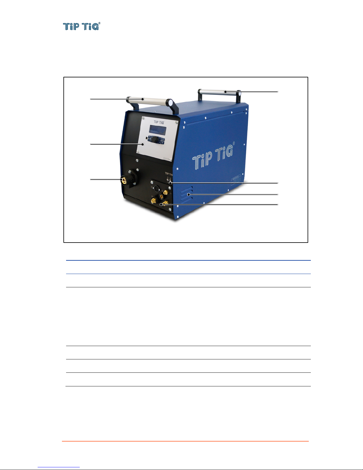
5.1 System overview
Front of TIP TIG – AllinOne wire feeder
No.
Description
(1)
Carrying handle
(2)
Control panel – See 5.7 Control panel
(3)
Hotwire indicator lamps
Temperature fault indicator (left)
is lit in the case of overheating. It extinguishes after a few minutes when the unit has
cooled down.
Hotwire-on indicator (right)
(1) is lit when there is live operating voltage and the hot wire unit is ready for service,
(2) blinks in case of a fault.
(4)
Wire electrode connection – for connecting the welding torch wire feed
(5)
Front connection – See 5.2 Front connection
(6)
Cooling air inlet
(5)
(4)
(3)
(2)
(1)
(1)
(6)

TIP TIG - ALLINONE, OPERATING MANUAL
Page 13 of 57
Rear of TIP TIG – AllinOne wire feeder
No.
Description
(1)
Main power switch with fuses – See 5.4 Main power switch with fuses
(2)
Cooling air outlet
(3)
Rear connection – See 5.3 Rear connection
(4)
Protective cap
Cover for the wire feed mechanism and other operating elements.
(5)
Lock for the protective cap
(1)
(3)
(4)
(5)
(5)
(2)
TIP TIG - ALLINONE, OPERATING MANUAL
Page 14 of 57
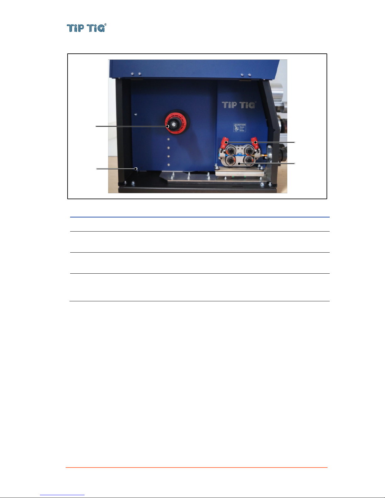
TIP TIG – AllinOne wire feeder: operating elements in the machine
No.
Description
(1)
Four roll wire drive
(2)
Clamping levers
for setting the contact pressure of the feed rollers
(3)
Hotwire amperage adjustment – See 5.5 Hotwire amperage adjustment
for adjusting the ampere setting of the hotwire unit
(4)
Wires pool holder with brake
for holding standard wire spools with max. diameter of 300 mm (11.81 in.) and max.
weight of 15 kg (33.1 lb.)
(1)
(4)
(3)
(2)

TIP TIG - ALLINONE, OPERATING MANUAL
Page 15 of 57
5.2 Front connection
No.
Description
(1)
Connection socket control lead (7-pole)
for connecting control lead from the welding torch hose package
(2)
Connecting nipple current / coolant supply (blue)
for connecting current / coolant supply (G3/8" RH) from the welding torch hose package
(3)
Connecting nipple shielding gas
for connecting shielding gas (G1/4" RH) from the welding torch hose package
(4)
Connecting nipple coolant return (red)
for connecting coolant return (G3/8" LH) from the welding torch hose package
(5)
Connection socket hot wire
for connecting hot wire power from the welding torch hose package, minus potential
(1)
(3)
(4)
(5)
(2)

TIP TIG - ALLINONE, OPERATING MANUAL
Page 16 of 57
5.3 Rear connection
No.
Description
(1)
Connector plug (7-pole) – option
for connecting TIP TIG Automation 0-10V (AUTOMATION ONLY)
(2)
Connection socket (7-pole)
Communication Connection for the welding machine
(3)
Connector plug (4-pole) – Mains connection
120/230 VAC main power connection
(4)
Connecting nipple shielding gas
for connecting shielding gas (G1/4" RH) from the interconnection hose package
(5)
Connecting nipple coolant supply (blue)
for connecting coolant supply (G3/8" RH) from the interconnection hose package
(6)
Connecting nipple coolant return (red)
for connecting coolant return (G3/8" LH) from the interconnection hose package
(7)
Connector plug hot wire and workpiece
for connecting hot wire power from the interconnection hose package, plus potential,
workpiece connection
(8)
Connector plug welding current
for connecting welding current, minus potential from the interconnection hose package
(3)
(6)
(1)
(2)
(5)
(4)
(7)
(8)
TIP TIG - ALLINONE, OPERATING MANUAL
Page 17 of 57
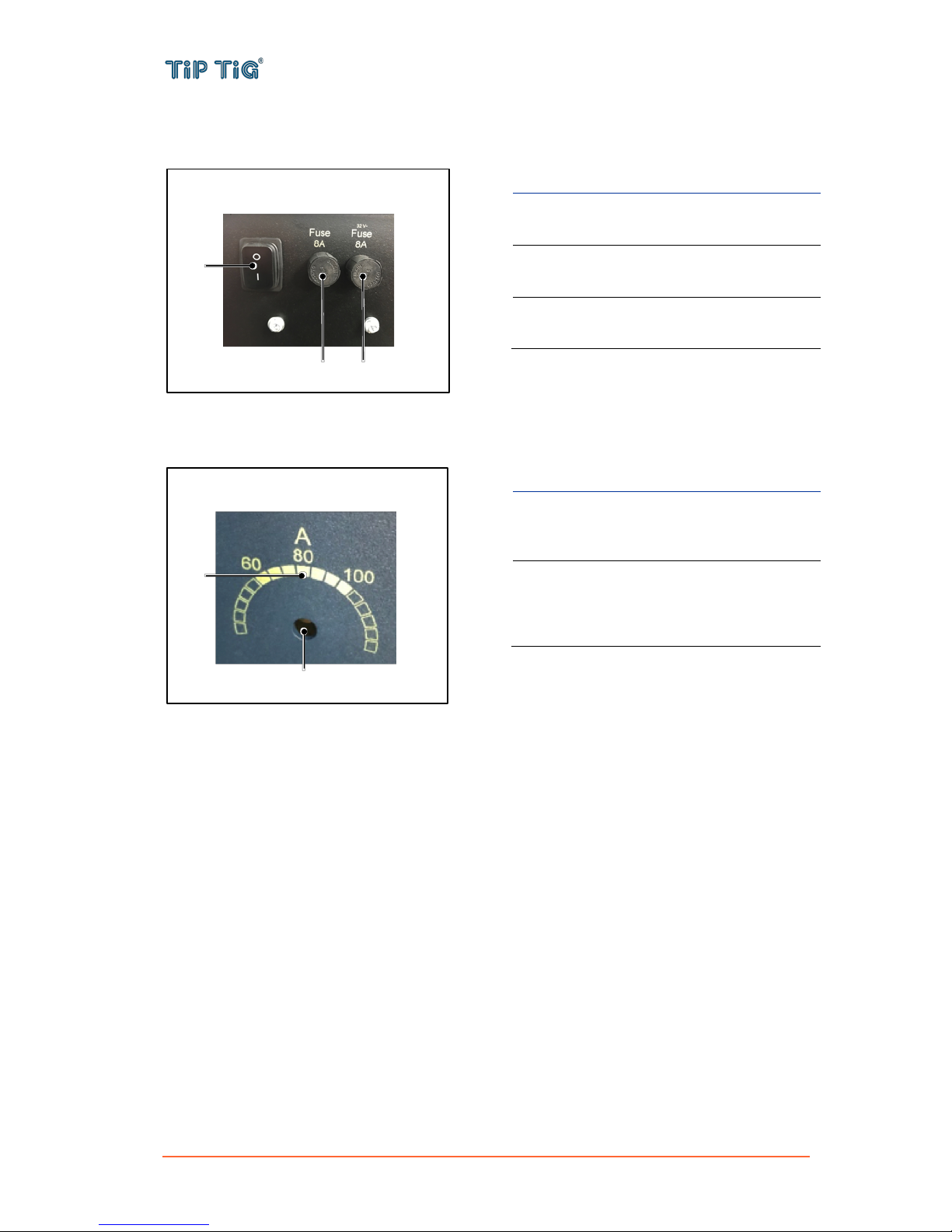
5.4 Main power switch with fuses
No.
Description
(1)
Main power switch
machine on/off
(2)
Mains fuse
T8 A, 120/230 VAC
(3)
Feeder fuse
T8 A, 32 VAC
5.5 Hotwire amperage adjustment
No.
Description
(1)
Adjustment screw
adjust the setting with a flat screw
driver
(2)
Adjustment range
60 – 100 A
Presetting 80 A (optimum setting
point)
(1)
(3)
(2)
(2)
(1)
TIP TIG - ALLINONE, OPERATING MANUAL
Page 18 of 57
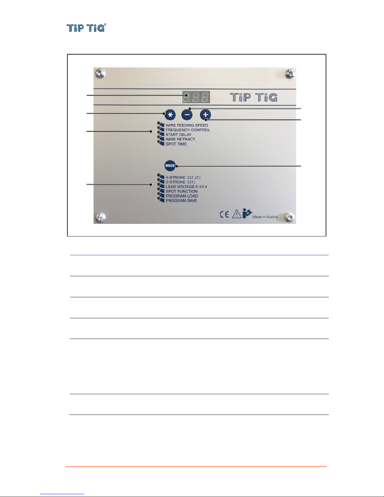
5.6 Control panel – D24B2M1.6
No.
Function
(1)
Display
shows the current figure of the selected parameter
(2)
Parameter selection button
for selecting the parameters listed below (5)
(3)
Adjusting button -
for negative adjustment of the selected parameter (5)
(4)
Adjusting button +
for positive adjustment of the selected parameter (5)
(5)
Parameter indicator
shows which parameter is selected:
- Wire Feeding Speed
- Frequency Control
- Start Delay
- Wire Retract
- Spot Time
(6)
Mode button
for selecting the desired mode (7)
(1)
(2)
(3)
(4)
(5)
(7)
(6)

TIP TIG - ALLINONE, OPERATING MANUAL
Page 19 of 57
(7)
Mode indicator
shows which mode is selected:
- 4-Stroke
- 2-Stroke
- Lead Voltage 0-10 V
- Spot Function
- Program Load
- Program Save
Display values
Wire Feeding Speed
Display value multiplied by 0,0635 is the wire feed speed in m/min
or display value multiplied by 2,5 is the wire feed speed in IPM
(WIRE FEED SPEED = 0,0635*Display value)
Example: Factor 100 = 6,35 m/min or 250 IPM
For more information please go to Appendix 9.2.1 or visit
https://www.tiptig.com/english/support/
Frequency Control
The value is as shown as factor
For all applications use 230 = 17 Hz
Start Delay
The value is as shown as factor (optional)
Useful for track weld
Wire Retract
The value is as shown as factor (optional)
Is an option – normally not used
Spot Time
The value is as shown as factor (optional)
Only for spot weld
To use spot time it's needed to adjust the mode spot function
Modes
4-Stroke
Generally select 4-Stroke mode for hand welding
2-Stroke
2-Stroke mode mostly used for tack welding
Lead Voltage 0-10 V
optional
Spot Function
optional
Program Load
optional
Program Save
optional
CAUTION
The wire feed speed may have a variation of ± 10%. It depends on
the settings of the feed roll tensioner (see 5.5 (2)) and the quality
of the wire.
TIP TIG - ALLINONE, OPERATING MANUAL
Page 20 of 57
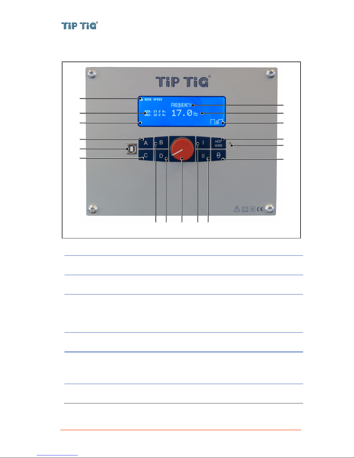
5.7 Control panel – Version 2.0
Display – Parameters and Modes
No.
Function
(1)
Menu (parameter) forecast up/down
shows which parameter will be selected when switching menu up/down
(2)
Parameter range indicator
shows min. and max. value of the selected parameter
(3)
Menu (parameter) indicator
shows which parameter is selected:
- Wire speed
- Frequency
- Weld amps
(4)
Parameter
shows the current value and unit of the selected parameter
(5)
Mode indicator
shows which mode is selected:
- 2-Step
- 4-Step
(6)
A – Menu (parameter) up button
switching menu up
(1)
(7)
(3)
(4)
(2)
(9)
(5)
(14)
(16)
(6)
(8)
(10)
(12)
(13)
(11)
(1)
(15)
Table of contents
Other TIP TIG Welding System manuals


Popular Welding System manuals by other brands

widos
widos 7000 WM quick start guide

Adtech
Adtech ADT-HC4500 user manual

Castolin
Castolin dyomix Oxy-Hydrogen Mobile 2.4 user manual

Lincoln Electric
Lincoln Electric Harris 62-E operating instructions

EWM
EWM Picotig 200 puls TG operating instructions

Asahi/America
Asahi/America McELROY SmartFab 125 Operator's manual

Lincoln Electric
Lincoln Electric RANGER 8 Operator's manual

Lincoln Electric
Lincoln Electric Square Wave TIG 200 Quick reference guide

Miller
Miller DYNASTY DX Technical manual

Nelson
Nelson NS-40 Instruction and maintenance manual

Pro-Weld
Pro-Weld CD-312 user manual

Alfain
Alfain PEGAS 160 MIG MAN operating manual


