TIP TIG TIG 500 FOCUS User manual
.
TIP TIG - TIG 500 FOCUS
Operating Manual
Version 1.1 Revision 0.1
TIP TIG – TIG 500 FOCUS
OPERATING MANUAL

TIP TIG - TIG 500 FOCUS, OPERATING MANUAL
Page 2 of 75
INTRODUCTION
Thank you for the trust you have placed in our company and congratulations on buying this high-
quality TIP TIG product. These instructions will help you familiarize yourself with the product.
Reading the instructions carefully will enable you to learn about the many different features it has to
offer. This will allow you to make full use of its advantages.
Please also note the safety rules to ensure greater safety when using the product. Careful handling
of the product will repay you with years of safe and reliable operation. These are essential
prerequisites for excellent results.

TIP TIG - TIG 500 FOCUS, OPERATING MANUAL
Page 3 of 75
CONTENTS
1.!GENERAL INSTRUCTIONS 5!
2.!INTENDED USE 6!
2.1!Declaration of conformity 6!
2.2!Welding in environments with increased electrical hazards 6!
2.3!Calibration/Validation 6!
3.!SAFETY RULES 7!
3.1!Explanation of safety symbols 7!
3.2!General safety instructions 7!
4.!GENERAL 10!
4.1!Device concept 10!
4.2!Crane transport 10!
5.!CONTROLS, CONNECTIONS AND MECHANICAL COMPONENTS 11!
5.1!System overview 11!
5.2!Front connection 14!
5.3!Main switch with fuses 15!
5.4!Connection socket relays 15!
5.5!Control Panel – Power Source 16!
5.6!Control Panel – FOCUS 19!
6.!INSTALLATION AND COMMISSIONING 27!
6.1!Before installation and commissioning 27!
6.2!Start-up – Power Source 28!
6.3!Start-up – Wire feeder 31!
7.!WELDING 36!
7.1!Preparation 36!
7.2!Operating modes 37!
7.3!Welding current types (TIG 500AC only) 40!
7.4!MMA welding 41!
7.5!TIG welding 42!
8.!TROUBLESHOOTING, MAINTENANCE AND DISPOSAL 44!
8.1!Troubleshooting 44!
8.2!Care, maintenance and disposal 49!
9.!TECHNICAL DATA 50!
10.!APPENDIX 52!
10.1!Installation Guide 52!
10.2!Welding Check List 58!

TIP TIG - TIG 500 FOCUS, OPERATING MANUAL
Page 4 of 75
10.3!Spare part list 60!
10.4!WIRING DIAGRAM 62!

TIP TIG - TIG 500 FOCUS, OPERATING MANUAL
Page 5 of 75
1. GENERAL INSTRUCTIONS
In the event of queries on installation, commissioning, operation or special conditions at the
installation site, or on usage, please contact your sales partner or our customer service
department on +43 720 303500 or office@tiptig.com.
A list of authorized sales partners can be found at www.tiptig.com.
Liability relating to the operation of this equipment is restricted solely to the function of the
equipment. No other form of liability, regardless of type, shall be accepted. This exclusion of liability
shall be deemed accepted by the user on commissioning the equipment.
The manufacturer is unable to monitor whether or not these instructions or the conditions and
methods are observed during installation, operation, usage and maintenance of the equipment.
An incorrectly performed installation can result in material damage and injure persons as a result.
For this reason, we do not accept any responsibility or liability for losses, damages or costs arising
from incorrect installation, improper operation or incorrect usage and maintenance or any actions
connected to this in any way.
© TIP TIG Automation GmbH, Baumayrweg 5, 4631 Krenglbach, Austria
The copyright to this document remains the property of the manufacturer. Reprinting, including
extracts, only permitted with written approval.
The content of this document has been prepared and reviewed with all reasonable care. The
information provided is subject to change, errors excepted.
CAUTION
Read the operating instructions!
The operating instructions provide an introduction to the safe use of the products.
• Read the operating instructions for all system components!
• Observe accident prevention regulations!
• Observe all local regulations!
• Confirm with a signature where appropriate.

TIP TIG - TIG 500 FOCUS, OPERATING MANUAL
Page 6 of 75
2. INTENDED USE
2.1 Declaration of conformity
The$labelled$machine$complies$with$the$following$EC$directives$and$standards$in$terms$
of$its$design$and$construction:!!
• "#$%&'(&)*!+,-!.,/0123!456370583!9+.4:!
• "#$%&'#&)*!)/3706,;12<3057!=,;>105?5/50@!456370583!9)A=:!!
• "#$$&B(&)*!C3D065705,<!,E!F1G16H,ID!JI?D01<73!9C,FJ:!
!
J01<H16HD!
!
• K)=!B#LM%N$O!"#$"!P67!-3/H5<2!3QI5>;3<0!N!R160!$O!S3/H5<2!>,-36!D,I673D!
• K)=!B#LM%N'O!"#$'!P67!-3/H5<2!3QI5>;3<0!N!R160!'O!P67!D065T5<2!D01?5/5G5<2!
H38573D!
• K)=!B#LM%N$#O!"#$%!P67!-3/H5<2!3QI5>;3<0!U!R160!$#O!)/3706,;12<3057!
7,;>105?5/50@!63QI563;3<0D!
! ! ! ! ! PI2ID0!$V!"#$W!
XXXXXXXXXXXXXXXXXXXXXXXXXXXXXX! ! ! XXXXXXXXXXXXXXXXXXXXXXXXXXXXXX!
YZ623<!R/1D7[V!=)\!!!!!4103!,E!437/16105,<!
K<! 71D3! ,E! I<1I0[,65G3H!7[1<23DV! 5;>6,>36! 63>156DV! 1<H&,6! >6,[5?503H! ;,H5E57105,<D! -[57[! [183! <,0!
?33<!3]>/5750/@!1I0[,65G3H!?@!^KR!^K_!PI0,;105,<!_;?FV!0[5D!H37/16105,<!D[1//!?3!8,5H3H`!
2.2 Welding in environments with increased electrical hazards
In$compliance$with$IEC$/$DIN$EN$60974,$VDE$0544$the$machines$can$be$used$in$
environments$with$an$increased$electrical$hazard.$$
2.3 Calibration/Validation
S3! [363?@! 7,<E56;! 0[10! 0[5D! ;17[5<3! [1D! ?33<! 03D03H! ID5<2! 71/5?6103H! ;31DI65<2! 3QI5>;3<0V! 1D!
D05>I/103H!5<! K)=&)a!B#LM%V! KJ\&)a!$MBB"V!)a! (#(#%V! 1<H!7,;>/53D! -50[! 0[3!1H;5DD5?/3!0,/361<73D`!
C37,;;3<H3H!71/5?6105,<!5<03681/O!$"!;,<0[D!
WARNING!
Hazards due to improper usage!
The machine has been constructed to the state of the art and any regulations and
standards applicable for use in industry and trade. It may only be used for the welding
procedures indicated at the rating plate. Hazards may arise for persons, animals and
material objects if the equipment is not used correctly. No liability is accepted for any
damages arising from improper usage!
• ^[3!3QI5>;3<0!;ID0!,</@!?3!ID3H!5<!/5<3!-50[!50D!H3D52<103H!>I6>,D3!1<H!?@!0615<3H!,6!
3]>360!>36D,<<3/b!
• 4,!<,0!5;>6,>36/@!;,H5E@!,6!7,<8360!0[3!3QI5>;3<0b$
Intended use
•
•
•
•
•
–
•
Intended use
•
•
•
•
•
–
•

TIP TIG - TIG 500 FOCUS, OPERATING MANUAL
Page 7 of 75
3. SAFETY RULES
3.1 Explanation of safety symbols
NOTE! Indicates a risk of flowed and possible damage to the equipment.
IMPORTANT! Indicates tips for correct operation and other particularly useful information. It does
not indicate a potential damaging or dangerous situation.
If you see any of the symbols depicted in the “Safety rules” chapter, special care is required.
3.2 General safety instructions
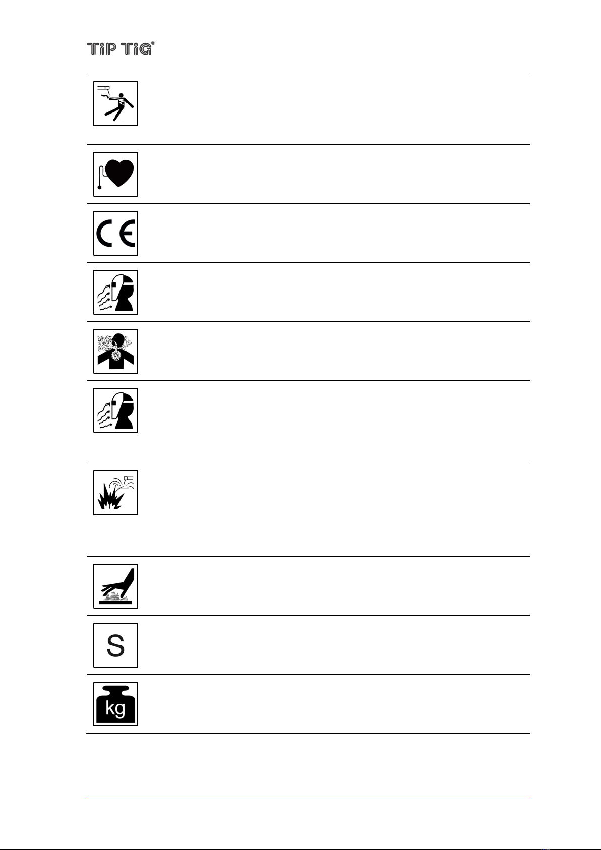
WARNING: This symbol indicates that instructions must be followed to avoid
serious personal injury, loss of life, or damage to this equipment. Protect yourself
and others from possible serious injury or death.
READ AND UNDERSTAND INSTRUCTIONS: Read and understand this manual
before operating this equipment. Arc welding can be hazardous. Failure to follow
the instructions in this manual could cause serious personal injury, loss of life, or
damage to this equipment.
ELECTRIC SHOCK CAN KILL: Welding equipment generates high voltages. Do
not touch the electrode, work clamp, or connected work pieces when this equipment
is on. Insulate yourself from the electrode, work clamp, and connected work pieces.
ELECTRICALLY POWERED EQUIPMENT: Turn off input power using the
disconnect switch at the fuse box before working on this equipment. Ground this
equipment in accordance with local electrical regulations.
DANGER! Indicates immediate and real danger. If is not avoided, death or serious
injury will result.
WARNING! Indicates a potentially situation. Death or serious injury may result if
appropriate precautions are not taken.
CAUTION! Indicates a situation where damage or injury could occur. If it is not avoided,
minor injury and/or damage to property may result.
CAUTION
This equipment must be used by qualified personnel. Be sure that all installation, operation,
maintenance and repair procedures are performed only by qualified person. Read and
understand this manual before operating this equipment. Failure to follow the instructions in this
manual could cause serious personal injury, loss of life, or damage to this equipment. Read and
understand the following explanations of the warning symbols. TIP TIG is not responsible for
damages caused by improper installation, improper care or abnormal operation.
TIP TIG - TIG 500 FOCUS, OPERATING MANUAL
Page 8 of 75
ELECTRICALLY POWERED EQUIPMENT: Regularly inspect the input, electrode,
and work clamp cables. If any insulation damage exists replace the cable
immediately. Do not place the electrode holder directly on the welding table or any
other surface in contact with the work clamp to avoid the risk of accidental arc
ignition.
ELECTRIC AND MAGNETIC FIELDS MAY BE DANGEROUS: Electric current
flowing through any conductor creates electric and magnetic fields (EMF). EMF
fields may interfere with some pacemakers, and welders having a pacemaker shall
consult their physician before operating this equipment.
CE COMPLIANCE: This equipment complies with the European Community
Directives.
ARTIFICIAL OPTICAL RADIATION: According with the requirements in
2006/25/EC Directive and EN 12198 Standard, the equipment is a category 2. It
makes mandatory the adoption of Personal Protective Equipment (PPE) having filter
with a protection degree up to a maximum of 15, as required by EN169 Standard.
FUMES AND GASES CAN BE DANGEROUS: Welding may produce fumes and
gases hazardous to health. Avoid breathing these fumes and gases. To avoid these
dangers the operator must use enough ventilation or exhaust to keep fumes and
gases away from the breathing zone.
ARC RAYS CAN BURN: Use a shield with the proper filter and cover plates to
protect your eyes from sparks and the rays of the arc when welding or observing.
Use suitable clothing made from durable flame-resistant material to protect you skin
and that of your helpers. Protect other nearby personnel with suitable, non-
flammable screening and warn them not to watch the arc nor expose themselves to
the arc.
WELDING SPARKS CAN CAUSE FIRE OR EXPLOSION: Remove fire hazards
from the welding area and have a fire extinguisher readily available. Welding sparks
and hot materials from the welding process can easily go through small cracks and
openings to adjacent areas. Do not weld on any tanks, drums, containers, or
material until the proper steps have been taken to ensure that no flammable or toxic
vapors will be present. Never operate this equipment when flammable gases,
vapors or liquid combustibles are present.
WELDED MATERIALS CAN BURN: Welding generates a large amount of heat.
Hot surfaces and materials in work area can cause serious burns. Use gloves and
pliers when touching or moving materials in the work area.
SAFETY MARK: This equipment is suitable for supplying power for welding
operations carried out in an environment with increased hazard of electric shock.
EQUIPMENT WEIGHT OVER 30kg: Move this equipment with care and with the
help of another person. Lifting may be dangerous for your physical health.

TIP TIG - TIG 500 FOCUS, OPERATING MANUAL
Page 9 of 75
CYLINDER MAY EXPLODE IF DAMAGED: Use only compressed gas cylinders
containing the correct shielding gas for the process used and properly operating
regulators designed for the gas and pressure used. Always keep cylinders in an
upright position securely chained to a fixed support. Do not move or transport gas
cylinders with the protection cap removed. Do not allow the electrode, electrode
holder, work clamp or any other electrically live part to touch a gas cylinder. Gas
cylinders must be located away from areas where they may be subjected to
physical damage or the welding process including sparks and heat sources.
CAUTION: The high frequency used for contact-free ignition with TIG (GTAW)
welding, can interfere with the operation of insufficiently shielded computer
equipment, EDP centers and industrial robots, even causing complete system
breakdown. TIG (GTAW) welding may interfere with electronic telephone networks
and with radio and TV reception.
NOISE APPEARES DURING WELDING CAN BE HARMFUL: Welding arc can
cause noise with high level of 85dB for 8-hour week day. Welders operating welding
machines are obligated to wear the proper ear protectors /appendix No. 2 for the
Decree of the Secretary of Labor and Social Policy from 17.06 1998 – Dz.U. No. 79
pos. 513/. According to the Decree the Secretary of Health and Social Welfare from
09.07.1996 /Dz.U. No. 68 pos. 194/, employers are obligated to carry examinations
and measurements of health harmful factors.
The manufacturer reserves the right to make changes and/or improvements in design without
upgrade at the same time the operator’s manual.

TIP TIG - TIG 500 FOCUS, OPERATING MANUAL
Page 10 of 75
4. GENERAL
4.1 Device concept
The TIP TIG FOCUS welding system is a
fully digitized and microprocessor-controlled
welding system specially developed for TIG
keyhole welding.
Thanks to its extremely focused arc, this
novel joining process enables a very high
energy density in the weld pool and highest
welding speeds. Reworking and preparatory
work can be significantly reduced.
4.2 Crane transport
The TIP TIG FOCUS can be transported by crane at the lifting eyes.
The maximum load-bearing capacity of the lifting eyes is 150 kg (330.69 lbs.)
Before transporting by crane:
- feed out the wire electrode, remove the wire spool
- disconnect the torch hose package and interconnecting hose package from the wire feeder
- if present, unplug the coolant connections
CAUTION
This welding system is designed and build for
FOCUS-welding. Manual welding isn‘t possible with
this welding machine.
WARNING
Falling equipment can cause death or serious injury.
• Only use a suitable lifting tackle when transporting devices by crane (e.g. belt with round
slings)
• The lifting tackle must be undamaged and in perfect condition
• Do not transport any other loads by the handle apart from the wirefeeder itself
• Do not hang from the wirefeeder as it is being transported
TIP TIG - TIG 500 FOCUS, OPERATING MANUAL
Page 11 of 75
5. CONTROLS, CONNECTIONS AND MECHANICAL COMPONENTS
5.1 System overview
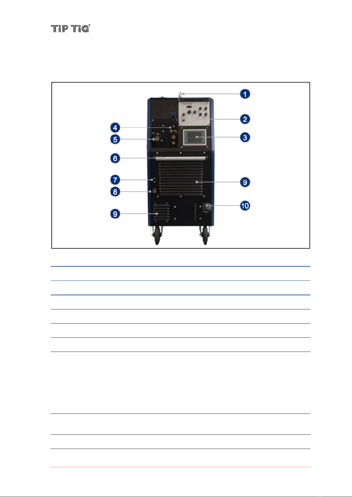
Front of TIP TIG – TIG 500 FOCUS
No.
Description
(1)
Transport eyebolt (Lifting lug)
(2)
Control Panel Power Source – See 5.5 Control Panel – Power Source
(3)
Control Panel FOCUS – See 5.6 Control Panel – FOCUS
(4)
Front connection – See 5.2 Front connection
(5)
Wire electrode connection – for connecting the welding torch wire feed
(6)
Transport handle
(7)
Hotwire indicator lamps
Temperature fault indicator (down)
is lit in the case of overheating. It extinguishes after a few minutes when the unit has
cooled down.
Hotwire-on indicator (top)
(1) is lit when there is live operating voltage and the hot wire unit is ready for service,
(2) blinks in case of a fault.
(8)
Connection socket, welding current „+“
for connecting the workpiece lead
(9)
Cooling air inlet

TIP TIG - TIG 500 FOCUS, OPERATING MANUAL
Page 12 of 75
(10)
Coolant tank with cap
Rear of TIP TIG – TIG 500 FOCUS
No.
Description
(1)
Transport eyebolt (Lifting lug)
(2)
Button gas test
(3)
24 pole connection socket rotary table – optional
for connecting a TIP TIG rotary table
(4)
RJ-45 female connector
for connecting a network cable
(5)
Connecting nipple shielding gas
for connecting the shielding gas (G1/4" RH) on the pressure regulator
(6)
7 pole connection socket relays – See 5.4 Connection socket
for connecting existing welding equipment such as longitudinal seam welding devices,
rotary tables, welding machine carrier, etc.
(7)
37 pole connection socket distributor box
for connecting the provided distributor box
(8)
Main switch with fuses – See 5.3 Main switch with fuses
(9)
Mains connection cable with plug
(10)
Securing elements for shielding gas cylinder (strap / chain)
TIP TIG - TIG 500 FOCUS, OPERATING MANUAL
Page 13 of 75
(11)
Cooling air outlet
(12)
Hotwire amperage adjustment
for adjusting the amperage setting of the hotwire unit. Adjustment with a flat screw driver.
Adjustment range: 60 – 100 A (Presetting 80 A)
(13)
Connecting socket
Output 230 VAC
(14)
Bracket for shielding gas cylinder
(15)
Wheels, fixed castors
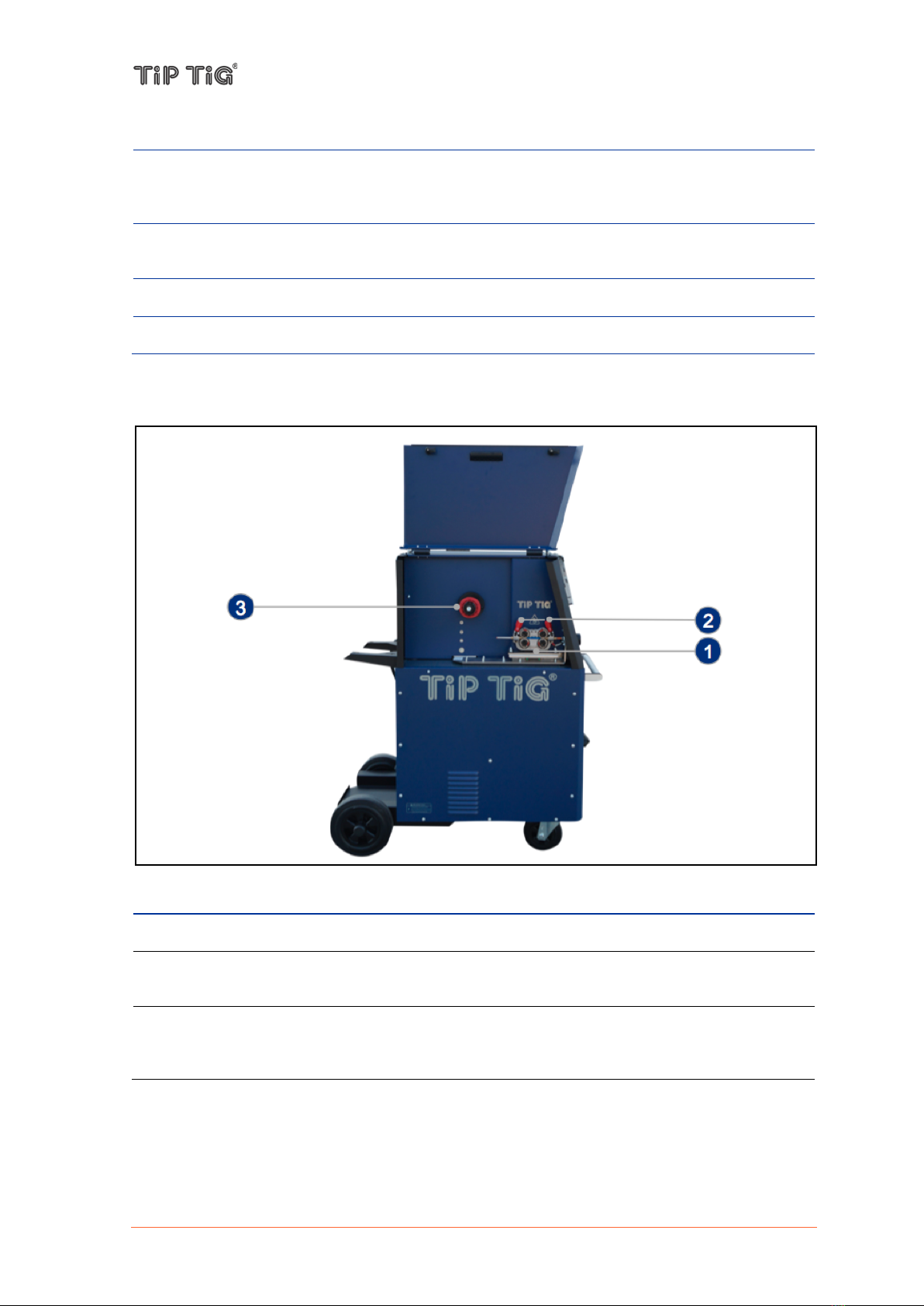
TIP TIG – TIG 500 FOCUS: operating elements in the machine
No.
Description
(1)
Four roll wire drive
(2)
Clamping levers
for setting the contact pressure of the feed rollers
(3)
Wires pool holder with brake
for holding standard wire spools with max. diameter of 300 mm (11.81 in.) and max.
weight of 15 kg (33.1 lb.)

TIP TIG - TIG 500 FOCUS, OPERATING MANUAL
Page 14 of 75
5.2 Front connection
No.
Description
(1)
17 pole connection socket hand control box
for connecting the provided hand control box
(2)
Connection socket hot wire
for connecting hot wire power from the welding torch hose package, minus potential
(3)
Connecting nipple coolant return (red)
for connecting coolant return (G3/8" LH) from the welding torch hose package
(4)
Connecting nipple shielding gas
for connecting shielding gas (G1/4" RH) from the welding torch hose package
(5)
Connecting socket, welding current „-“
for connecting TIG welding torch / electrode holder
(6)
Wire electrode connection – for connecting the welding torch wire feed
(7)
Connecting nipple current / coolant supply (blue)
for connecting current / coolant supply (G3/8" RH) from the welding torch hose package

TIP TIG - TIG 500 FOCUS, OPERATING MANUAL
Page 15 of 75
5.3 Main switch with fuses
No.
Description
(1)
Main switch
Machine on/off
(2)
Fuse F1
T8 A, 230 VAC
(3)
Fuse F2
T8 A, 0 VAC
5.4 Connection socket relays
Existing welding equipment can be controlled via the 7-pole panel socket
No.
Configuration
No.
Example – Longitudinal seam welding
device
1
Relays 1_1
1
Forward
2
Relays 1_2
2
Forward
3
Relays 2_1
3
Backward
4
Relays 2_2
4
Backward
5
Not assigned
5
Not assigned
6
Not assigned
6
Not assigned
7
Ground
7
Ground
TIP TIG - TIG 500 FOCUS, OPERATING MANUAL
Page 16 of 75
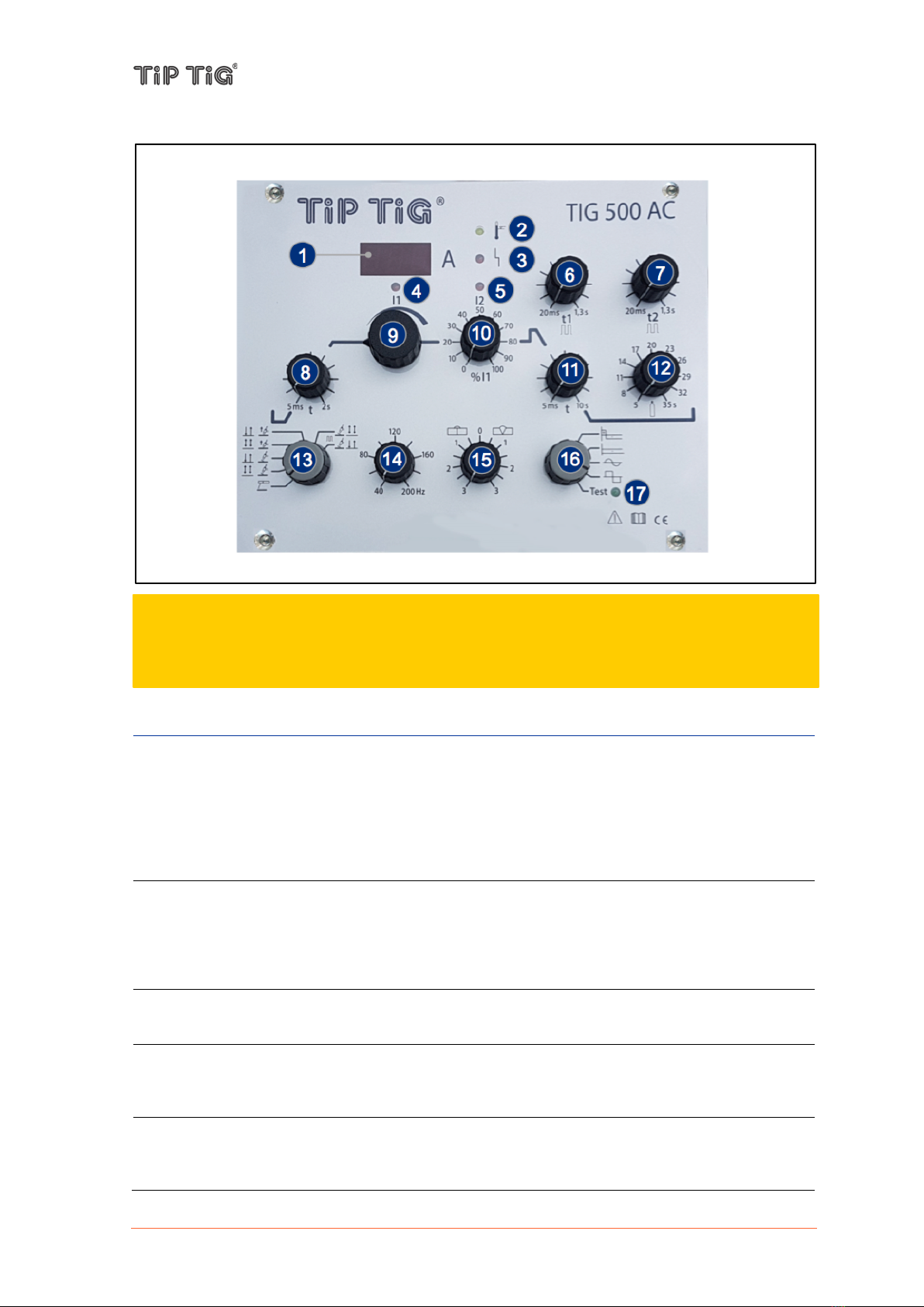
5.5 Control Panel – Power Source
No.
Function
(1)
Welding data display (3-digit)
displays the current value of the welding current as well as error messages:
- In normal operation, the welding current is displayed.
- If a fault occurs in the cooling system, the welding process is switched off and the
message "H2O" flashes together with (2) Overheat Indicator
- In the event of a mains or inverter fault as well as overheating, the display flashes "- - -"
and the welding process is switched off.
(2)
Overheat Indicator
lights up when the power source has overheated and turned off (for example, due to the
duty cycle being exceeded). It extinguishes when the unit is cooled down and is ready
for welding.
If there is a lack of water, the display flashes.
(3)
Inverter Fault Indicator
lights up if there is a mains under voltage or a defect in the welding inverter.
(4)
Welding Current I1 Indicator
lights up when welding current I1 is active. With TIG pulses, this corresponds to the
pulse current phase.
(5)
Welding Current I2 Indicator
lights up when welding current I2 is active. With TIG pulses, this corresponds to the
basic current phase.
CAUTION
This welding system is designed and build for FOCUS-welding. Manual welding isn‘t possible
with this welding machine.

TIP TIG - TIG 500 FOCUS, OPERATING MANUAL
Page 17 of 75
(6)
Pulse Time t1 Rotary Knob
for setting the pulse time t1, while welding current I1 is active during TIG pulses. (Range:
20ms - 1.3sec.)
(7)
Pulse Time t2 Rotary Knob
for setting the pulse time t2, while welding current I2 is active during TIG pulses. (Range:
20ms - 1.3sec.)
(8)
Soft Start (Upslope) Rotary Knob
for setting the soft-start time, in which the welding current is increased to the set value.
(Range: 5ms - 2sec.). In 2-stroke mode, the welding current starts in the minimum, in 4-
cycle mode with the starting current (20% of the welding current I1)
(9)
Welding Current I1 Rotary Knob
for adjusting the welding current I1:
- Setting range TIG: 4A - 500A
- Setting range MMA: 15A - 400A
(10)
Welding Current I1 Rotary Knob
for adjusting the welding current I2 (range: 0% - 100%). In 2-stroke operation, the
welding current starts in the minimum, in 4-stroke operation with the starting current
(20% of the welding current I1). The maximum adjustable welding current I2 always
corresponds to the set value of I1. This welding current is used as a base current during
pulsing.
(11)
Soft Down (Downslope) Rotary Knob
for setting the soft-down time (range: 5ms - 10sec.) at which the welding current is
reduced from the set value to min.
(12)
Gas Post-Flow Time Rotary Knob
for adjusting the gas post-flow time during TIG welding (range: 5sec - 35sec.). If started
but not welded, the gas post-flow time does not expire.
(13)
Operating Mode Rotary Knob
for setting the operating mode, see 7.2 Operating modes:
- MMA
- TIG 4-Stroke
- TIG 2-Stroke
- TIG Liftarc 4-Stroke
- TIG Liftarc 2-Stroke
- TIG Pulse 4-Stroke
- TIG Pulse 2-Stroke
(14)
Frequency Rotary Knob (AC only)
for adjusting the frequency of the AC arc (range: 40Hz - 200Hz)
(15)
Balance Rotary Knob (AC only)
for adjusting the balance of the AC arc (range: 80:20 - 20:80). As a result, either a deep
penetration or a high cleaning effect can be set.
(16)
Welding Current Type / S-Test Rotary Knob (AC only)
for setting the welding current type, see 7.3 Welding current types (TIG 500AC only):
- DC welding with pulse start
- DC welding
- AC welding sinus (soft)
- AC welding rectangle (hard)
- S-Test

TIP TIG - TIG 500 FOCUS, OPERATING MANUAL
Page 18 of 75
(17)
S-Test indicator (AC only)
lights up when the Current Type / S-Test Rotary Knob is set to S-Test mode and the
inverter is operating correctly, see 7.1.1 S-Test (AC only)

TIP TIG - TIG 500 FOCUS, OPERATING MANUAL
Page 19 of 75
5.6 Control Panel – FOCUS
FOCUS – Home Screen
No.
Function
(1)
WELDING PARAMETERS Display
displays the welding parameter (left) and the corresponding value (right). The value can
be changed by touching the screen in the framed area:
- WELD AMPS
- WIRE SPEED
- TEST MODE
(2)
MOTION PARAMETERS Display
displays the motion parameter (left) and the corresponding value (right). The value can
be changed by touching the screen in the framed area:
- WELD SPEED
- ROTATING DIRECTION
(3)
ENERGY PARAMETER Display
displays the energy parameter and its value:
- VOLTAGE (left)
- HEAT INPUT (right)
(4)
Software version number
displays the version number of the installed TIP TIG software
(A)
Home Button
Touching the screen in the black area labeled "HOME" will select the Home Screen.
(B)
Settings Button
Touching the screen in the black area labeled "SETTINGS" will select the Settings
Screen.

TIP TIG - TIG 500 FOCUS, OPERATING MANUAL
Page 20 of 75
(C)
Gas Test Button
Touching the screen in the black area labeled "GAS TEST" will perform a gas test.
(D)
Offset Settings Button
Touching the screen in the black area labeled "OFFSET SETTINGS" selects the Offset
Settings Screen.
FOCUS – Settings Screen
No.
Function
(1)
WELDING SETTINGS Display
displays the welding settings (left) and the corresponding value as well as the range (min
- max.) (right). The value can be changed by touching the screen in the framed area:
- EVENT 1: AEA (automatic torch height adjustment)
- EVENT 2: PRE-GAS (gas pre-flow time)
- EVENT 3: UPSLOPE (arc upslope time)
- EVENT 4: WIRE DELAY (wire delay)
- EVENT 5: TRAVEL DELAY (welding delay)
- EVENT 6: DOWNSLOPE (arc downslope time)
- EVENT 7: DOWNSLOPE - WIRE (wire feed downslope time)
- EVENT 8: TORCH LIFT (burner lift at the end of the welding process)
(2)
AVC SETTINGS Display
indicates the ACV setting ON / OFF.
(3)
SETTINGS (AVC Settings) Button
Touching the screen in the framed area labeled "SETTINGS" selects the AVC Settings
Screen.
Table of contents
Other TIP TIG Welding System manuals


Popular Welding System manuals by other brands

Kemppi
Kemppi KEMPOMAT 320 KEMPOMAT 320C operating instructions

SIP
SIP HG4500 instruction manual

Parkside
Parkside PFDS 120 A2 Translation of the original instructions

Solda
Solda PL40E manual

Hobart Welders
Hobart Welders H100L4-10 owner's manual

Lincoln Electric
Lincoln Electric Prism 13264 Operator's manual


Trafimet
Trafimet ERGOCUT AW 201 quick start guide

AUTO ARC
AUTO ARC 255 owner's manual

Lincoln Electric
Lincoln Electric AC-225 Technical specifications

EWM
EWM Tetrix 551 AC/DC Smart FW operating instructions

Lincoln Electric
Lincoln Electric K386 Operator's manual

Lincoln Electric
Lincoln Electric Vernon Tool MasterPipe Compact Profiler Operator's guide