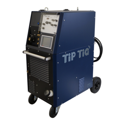
TIP TIG Hot Wire Unit User manual

TIP TIG TECHNICAL MANUAL
V4.5
www.tiptigusa.com 155 E 9th Ave Suite A, Runnemede, NJ 08078

Preface
We are very pleased that you have chosen to place your trust in our product. We
place great value in ensuring that you draw great pleasure, benefit and work
enhancement from your use of the TIPTIG Hot Wire Unit.
For that reason, we would like you to read through the Technical Manual thoroughly
before installing and starting to use the TIPTIG Hot Wire Unit.
It will help you to familiarize yourself with your new product as rapidly as possible and
to use it more efficiently.
This Technical Manual details the TIPTIG Hot Wire Unit, providing you with assistance
and support in installing it and getting started, as well as demonstrating how to use it
safely and effectively
The Manual is structured as follows:

TABLE OF CONTENTS
SECTION I − SAFETY PRECAUTIONS - READ BEFORE USING Pg
I-I Symbol Usage 1
I-II Arc Welding Hazards 1
I-III Additional Symbols For Installation, Operation and Maintenance 2
I-IV California Safety Standards 3
I-V Principal Safety Standards 3
I-VI EMF Information 3
SECTION II − Labels+symbols,Safety instruction especially TIPTIG
II-I Labelling+Symbols 4
II-II Safety instructions (CE) 5
II-III Safety instructions (CE) 6
II-IV Safety instructions (CE) 7
SECTION III − Installation-Getting Started
III-I Installation/Getting Started 8
III-II Getting Started 9
III-III Getting Started 10
III-IV What is the TIP TIG Process, How is it operated and Benefits 11
III-V Wire Selection 12
III-VI Tungsten Selection and Angles 13-14
III-VII Teflon Guide inside the feeder 15
III-VIII Loading wire for the first time 16-19
SECTION IV − Introduction-Tips-Warnings
IV-I Introduction 20
IV-II Tips II Function of TIP TIG Torch 18 SC 21-22
IV-III Tips III Function of TIP TIG Interconnect Cable 23
IV-IV Tips IV Function of Interface board 24
SECTION V − Pictures/Spare parts numbers
V-I Front View TIP TIG 25
V-II Left + Right Side TIP TIG 26
V-III Parts list TIPTIG Hot Wire Unit 27
V-IV Parts list 4-rolls Wire Feeder 28
V-V Picture Inside Connection Hot Wire Module 29
V-VI Spare list inside connection Hot Wire Module 30
V-VII Wire Feeder Diagram and Parts Breakdown 31-32
SECTION VI –Warranty 33
SECTION VII WP18 SC JUMBO / MEDIUM CONFIGURATION 34-35
SECTION VIII WP20 SC JUMBO / MEDIUM CONFIGURATION 36-37
SECTION IX WP 18 / 20 Torch Instruction Guide 38-42
SECTION X TIPTIG Hotwire Spare box TW18 SC-JUMBO 43-44

TABLE OF CONTENTS
SECTION XI WP 410 Straight (Handheld Addition) 45
SECTION XII Straight Handheld / Fixed Instruction Guide 46
SECTION XIII WP 410 Straight (Fixed Addition) 47
SECTION XIV TIP TIG FEEDER PC BOARD DIAGRAM 48
SECTION XV TIP TIG HOTWIRE CASE DIAGRAM 49 -51
SECTION XVI Miller Maxstar / TIP TIG Setup 52
SECTION XVII Miller Dynasty / TIP TIG Setup 53
SECTION XVIII MILLER MAXSTAR 350 / DYNASTY 350 54-55
BASIC SETTINGS
SECTION XIX TIP TIG Data Sheet 56
SECTION XX Troubleshooting 57-58-59

Protect yourself and others from injury-read and follow these precautions
I - I Symbol Usage
Instead of the examination mark, the danger sign often shows
the source of the danger in question. The yellow highlighted text
contains details of how to prevent personal injury or substantial
damage to property
Failure to comply with the instructions given may pose risk This group of symbols means Warning! Watch Out!
of injury '-or even danger of life! ELECTRIC SHOCK,MOVING PARTS, and HOT PARTS hazards.
Consult symbols and related instructions below for necessary
NOTICE- Indicates statements not related to personal injury actions to avoid the hazards
I - II Arc Welding Hazards
The symbols shown below are used throughout this manual to Properly install and ground this equipment according to the
call attention to and identify possible hazards. When you see the Owner's Manual and national,state,and local codes.
symbol, watch out, and follow the related instructions to avoid the Always verify the supply ground-check and be sure that input
hazard. The safety information given below is only a summary of power cord ground wire is properly connected to ground terminal
he more complete safety information found in the Safety in disconnected box or that cord plug is connected to a properly
Standards listed in Section 1-V.Read and follow all Safety grounded receptacle outlet.
Standards When making input connections, attach proper grounding conductor-
tor first-double-check connections.
Only qualified persons should install,operate,maintain,and Keep cords dry, free of oil and grease, and protected from hot
repair this unit metal and sparks.
Frequently inspect input power cord for damage or bare wiring-
During operation, keep everybody, especially children, away. replace cord immediately if damaged-bare wiring can kill.
Turn off all equipment when not in use.
ELECTRIC SHOCK can kill. Do not use worn,damaged,undersized,or poorly spliced cables.
Touching live electrical parts can cause fatal shocks or severe Do not drape cables over your body.
burns. The electrode and work circuit is electrically live whenever If earth grounding of the work piece is required, ground it directly
the output is on. The input power circuit and machine internal with a separate cable.
circuits are also live when power is on. In semiautomatic or Use only well-maintained equipment. Repair or replace damaged
automatic wire welding, the wire, wire reel, drive roll housing parts at once. Maintain according to manual.
and all metal parts touching the welding wire are electrically live. Wear a safety harness if working above floor level.
Incorrectly installed or improperly grounded equipment is a Keep all panels and covers securely in place.
hazard. Clamp work cable with good metal-to-metal contact to work piece
Don't touch live electrical parts. or worktable as near the weld as practical.
Wear dry, hole-free insulating gloves, and body protection Insulate work clamp when not connected to workspace to prevent
Insulate yourself from work and ground using dry insulating mats or contact with any metal object.
covers big enough to prevent any physical contact with the of ground.
Do not use AC output in damp areas, if move, movement is confined, or SIGNIFICANT DC VOLTAGE exists in Inverter welding
if there is a danger of falling. power sources AFTER removal of input power!
Use AC output ONLY if required for the welding process. Turn OFF inverter,diconnect input power, and discharge input
If AC output is required, remote output control is present on unit. capacitors according to instructions in Maintenance Section
Additional safety precautions are required when any of the following before touching any parts.
electrically hazardous conditions are present: in damp locations or while
wearing wet clothing: on metal structures such as floors,gratings,or HOT PARTS can burn.
scaffolds; when in cramped positions such as sitting,kneeling,or lying, Do not touch hot parts bare handle.
or when there is a high risk of unavoidable or accidental contact with Allow cooling period before working on equip-
the work piece or ground. ment.
Disconnected input power or stop engine before installing or servicing To handle hot parts, use proper tools and/or
this equipment. Lockout/tag out input power according to wear heavy, insulated welding gloves and
OSHA 29 CFR 1910.147 (see Safety Standards). clothing to prevent burns.
SAFETY PRECAUTIONS -READ BEFORE USING
1
SECTION I

I - III Additional Symbols For Installation,Operation,And Maintenance
FIRE OR EXPLOSION hazard. MOVING PARTS can injure.
Do not install or place unit on,over,or near combustible Keep away from moving parts such as fan
surfaces Keep all doors,panels,covers and guards closed
Do not install unit near flammables. and securely in place
Have only qualified persons remove doors,panels,covers, or
Do not overload building wring,-be sure power supply system is guards for maintenance and troubleshooting as necessary.
properly sized,rated,and protected to handle this unit Reinstall doors,panels,covers or guards when maintenance is
finished and before reconnecting input power.
FALLING EQUIPMENT can injure.
Use lifting eye to lift unit only, NOT running gear, gas READ INSTRUCTIONS
cylinders, or any other accessories. Read and follow all labels and the Owner's
Use equipment of adequate capacity to lift and support unit. Manual carefully before installing, operating or
servicing unit. Read the safety information at
the beginning of the manual and in each section
If using lift forks to move unit, be sure forks are long enough to extend Use only genuine replacement parts from the manufacturer.
beyond opposite side of unit. Perform maintenance and service according to the Owner's
Keep equipment (cables and cords)away from moving vehicles when Manuals, industry standards, and national,state,and local codes
working from an aerial location
Follow the guideline in the Applications Manual for the Revised NIOSH H.F.RADIATION can cause interference.
Lifting Equation (publication No.94-110) when manually heavy parts High-frequency (H.F) can interference with radio
or equipment. navigation, safety services,computers,and
communications equipment.
OVERUSE can cause OVERHEATIING Have only qualified persons familiar with
Allow cooling period, follow rated duty cycle electronic equipment perform this installation
Reduce current or reduce duty cycle before starting to The user is responsible for having a qualified electrician promptly
weld again correct any interference problem resulting from the installation
Do not block or filter airflow to unit. If notified by the FCC about interference, stop using the equipment
at once.
FLYING SPARKS can injure. Have the installation regularly checked and maintained.
Wear a face shield to protect eyes and face Keep high-frequency source doors and panels tightly shut, keep
Shape tungsten electrode only on grinder with proper sparks gaps at correct setting, and use grounding and shielding
guards in a safe location wearing proper face,hand,and to minimize the possibility of interference.
body protection.
Sparks can cause fires-keep flammables away.
STATIC (ESD) can damage PC boards
Put on grounded wrist strap BEFORE handling boards or
parts.
Use proper static-proof bags and boxes to store,move,or
ship PC boards.
MOVING PARTS can injure.
Keep away from moving parts
Keep away from pinch points such as drive rolls.
WELDING WIRE can injure.
Do not press gun trigger(button) until instructed to do so.
Do not point gun toward any part of body, other people,
or any metal threading welding wire
2
SECTION I

I - IV
CALIFORNIA PROPOSITION 65 WARNINGS
Welding or cutting equipment produces fumes or gases which
contain chemicals known to the State of California to cause birth
defects and ,in some cases, cancer,
(California Health & Safety Section 25249.5 et.seq.)
I - V Principal Safety Standards
Safety in Welding,Cutting,and Allied Processes
ANSI StandardZ49.1 from Globa l Engi neering Documents
(www.globa l.ihs .com)
Safety in Welding,Cutting,and Allied Processes
CSA Standard W 117.2 from Ca nadia n Standa rds Ass ociati on
(www.csa -i nternationa l.com)
OSHA,Occupational Safety and Health Standards for
General Industry
Title 29,Code of federal Regulations(CFR) Part 1910,Subpart Q
and Part 1926,SubpartI from Government Printing Office
(www.osha.gov)
I - VI EMF Information
Electric current flowing through any conductor causes localized 4 Keep head an trunk as far away from the equipment in the
electric and magnetic fields(EMF).Welding current creates an EMF field welding circuit as possible.
around the welding circuit and welding equipment.EMF fields may 5. Connect work clamp to work piece as close to the weld as
interfere with some medical impl ants, e.g. pea cema kers. possible.
Protective measures for persons wearing medical implants have to
6. Do not work next to, sit or lean on the welding power source.
be taken. For example, access restrictions for passers-by or individual
7. Do not weld whilst carrying the welding power source or wire
risk assessment for welders. All welders should use the following feeder.
procedures in order to minimize exposure to EMF fields from the
welding circuit:
1. Keep cables close together by twisting or taping them, or using
a cable cover.
2. Do not place your body between welding cables. Arrange cables
to one side and away from the operator
3. Do not coil or drape cables around your body
3
SECTION I

Symbols used in the Manual
This Technical manual uses a range of symbol and pictograms. You will need to
familiarize yourself closely with their meanings.
The symbols will help you to understand the information presented more rapidly and
point out of potentially important information, hints and tips.
Pay attention to the instructions and information presented adjacent to these
symbols with particular care
Danger sign Instead of the examination mark, the danger sign often shows the source of
the danger in question. The yellow highlighted text contains details of how
to prevent personal injury or substantial damage to property.
Failure to comply with the instructions given may pose risk of injury
-or even danger of life!
Prohibition sign The prohibition sign often shows the action or object which is prohibited.
The text accompanying this symbol details things to be avoided in order
to prevent personal injury or damage to property.
Essential action sign The action required (such as wearing protective equipment) is detailed in
in place of exclamation mark. Identifies essential action to be taken in order
to prevent injury.
Caution sign The text accompanying this symbol details action to be taken in order to
prevent damage.
Information sign Note, information or tip as a help in enhancing use of the equipment
Hand book sign Read the instructions-For your own safety and to avoid risk, be sure to
read and follow the instructions set out in this Technical Manual
SECTION 2 SAFETY INSTRUCTIONS
4
SECTION II-I

General safety instructions
The recognized technical rules and applicable standards and regulations
were followed and applied in the development and manufacture of the
TIPTIG High Speed Hot Wire Unit.
The TIPTIG High Speed Hot Wire Unit is designed and manufactured such that,
if used in accordance with it's designed purpose, any potential danger is
largely avoided.
Ing.Siegfried Plasch nonetheless feels obliged to detail the following safety
precautions which you should undertake in order to avoid any residual risk
Follow the operating Caution! When using TIPTIG Hot Wire Unit, the following fundamental
instructions! safety precautions must be taken in order to protect against electric
shock, potential injury and fire risk. Read and follow the instructions
for use,cleaning,care and maintenance given in this Technical Manual
before beginning work. Keep the Technical Manual within easy reach of
the machine operator and pass it on to new operators as and
when appropriate
The TIPTIG High Speed Hot Wire Unit is only for commercial and
industrial use. Any other use of this machine must be authorized in writing
by the manufacturer-Ing.Siegfried Plasch. Only personnel that have trained
for use and servicing of welding equipment may operate this machine
The operator for this equipment must carefully read and fully understand
all the information contained within before the unit can be put into
operation!
The information contained in this manual has been given the
manufacturer's best knowledge. However, the manufacturer can't be held
liable for the use of this information
Ing.Siegfried Plasch reserves the right to make any changes to this
machine and/or operations manual without prior notice.
Check function! Before beginning work, check that the guards and the TIPTIG Hot Wire Unit
itself are in good working order. Check the torch and machine for damage
and make sure that all parts in good working order!
Look out for damage! All parts must be correctly fitted and all conditions to met ensure trouble-free
operation of the machine. If the machine is damaged in any way, it must
no longer be used. In such cases, ensure that the machine is professionally
repaired. Identify the defect and mark the machine clearly so that it is not
used until such time as the repair has been carried out.
Maintain good order! Maintain good order in your work area! Disorder in a work area can cause
accidents. Secure your workplace when leaving it.
SAFETY INSTRUCTIONS
5
SECTION II-II

Installation and servicing of the TIPTIG Hot Wire unit welding machines
and components may only be performed in accordance with the national
rules and regulations of the respective organization operators safety.
Never come into contact with any metal parts that are under stress or
use with bare hands or wet clothing. During welding operation always wear
safety gloves, welding helmet with correct filter!
Be especially careful that anything, such as clothing that comes in
contact with the work area including the welding torch, welding ground
clamp and welding machine are always dry.
Never work in wet clothing!
When working with metal in the work area or in areas with high voltage
always be sure that all metal parts are isolated. Always use dry gloves
and wear rubber soled shoes!
Also, make sure that you are standing on a dry, isolated underlay!
Do not use any worn or damages welding cable!
Make sure that any welding cables are not overloaded!
Turn off the TIPTIG Hot Wire Unit and the welding machines if it is not
in use for long periods of time!
Do not leave the welding cable coiled up and do not wrap it around any
parts of the equipment casing!
When leaving the TIPTIG Hot Wire Unit and the welding unit, make sure
that it has been turned off and never leave it running unattended!
Make sure that the welding ground is connected close by the welding area
to the work piece!
Poor Welding ground connections, or poor grounding taken from parts of
the building or remote points decrease efficiency.
Furthermore the risk of electrical damage to equipment will increase!
Make sure that welding voltage can not come into contact with any chains
or steel ropes from equipment such as powered lifts and cranes!
Wear suitable work wear Damaging effect of the rays generated by the electrical arc and from any
and personal safety gear! hot metals can lead to severe burns to unprotected skin and eyes.
To protect your eyes and body from damaging sparks and rays always use
welding helmets with the proper certified filter lens. Also, wear the proper
protective clothing etc., even if you are only observing the welding process
Any person in the vicinity of the work area must be advised not to look
directly into the arc and that metal sparks could be sent through the air.
Protect your skin and hair with leather gloves and a welding helmet/mask
from the rays and metal sparks emitted.
Protect the personnel in the surrounding work area from the welding rays
and hot sparks with approved anti-flame retardant gear.
Gas tanks under pressure are a potential danger. Follow all safety
measures as suggested by gas suppliers and the safety procedures
imposed by safety inspectors!
Make sure that gas tanks are in a safe place and cannot fall over!
SAFETY INSTRUCTIONS
6
SECTION II-III

7
SECTION II-IV
Do not use the welding equipment close to flammable liquids or gases!
Danger from electrical energy! There is electrical equipment inside the TIPTIG Hot Wire Unit. Check the
machine for external damage before beginning work. Check especially
if wires and cables are damaged.
Do not continue working with the equipment if it is damaged.
Pull the plug! In the event of repairs and maintenance work, or when the
equipment is not in use, always disconnect the mains power supply plug
from wall socket
WARNING! Work on the electrical equipment may only be carried out by a
qualified electrician. Only original spares may be used. Failure to comply
with this requirement may result in users suffering accidents
Use only original parts! WARNING! Use only spares as specified in this Manual. The use of non-
approved parts may pose a risk of injury to you.
SAFETY INSTRUCTIONS

Make sure the correct power The TIPTIG Hot Wire Unit must be connected to a socket outlet fitted
supply is connected! with a properly installed ground contact.
Before connecting the TIPTIG Hot Wire Unit, make sure the main
power cable and the plug are undamaged. Make sure the main voltage
matches the specifications on the rating plate.
The TIPTIG Hot Wire Unit may only be connected to a voltage
of 115/120VAC /50/60Hz.
The power circuit must be fuse-protected to a maximum of 16A.
Recommendation: To protect you against electric shock, the circuit should
be protected by an GFI circuit-breaker(ground fault circuit-breaker)
The TIPTIG Hot Wire Unit can now be operated as detailed in the "Operator control"
section
Using in tanks and Don't take the TIPTIG Hot Wire Unit into a tank or container
container structures! structure!
It's possible to take only the TIPTIG Feeder into any tank and container
structure!
You have only to separate the TIPTIG Feeder from the TIPTIG
Trolley!
In this case the operating supply voltage is only 32 VAC!
Installation/Getting started
8
SECTION III-I

Getting start step 1 Connect the TIPTIG Hot Wire Unit interconnecting cable to
welding machine.
Connection step 2 Plug the TIPTIG Hot Wire Unit main cable plug to the socket
Only 115/120 VAC socket
Connection step 3 Put the wire spool in the spool holder and secure the spool with
the plastic nut an secure the plastic nut with the plastic screw!
Feed the wire by hand through the 4 feeder rollers and through
out the central torch connector about 2 inches
Connect the TIPTIG torch to the TIPTIG feeder
Check that all connections are tight!
Getting Started
9
SECTION III-II

The Hotwire Power Switch is located in the front on the unit.
Press the I/O rocket switch to POWER ON the Hotwire Process.
If AC Welding. DO NOT USE HOTWIRE….Power Off Hotwire
When first Powered On, The LED Indicator light
will flash several times then become solid.
The Hot Wire Unit is activated.
The Hot Wire Amp Range is from 60 to 100.
Recommended Setting is 80 Amps for All Alloys and Steels
SECTION III-III Getting Started
10

What is the TIP TIG process?
The TIP TIG process is a dynamic GTAW process that combines our
patented vibratory effect of the wire in part with a hotwire current
applied to the wire prior to entering the weld puddle.
•The vibratory effect is created by a linear forward/backward
mechanical motion created by the custom wire feeder system
•The Hotwire current is created by a secondary power source within
the Tip Tig unit.
How is the TIP TIG Process Operated?
•The TIP TIG process is operated by using a standard solid core MIG spool, a
conventional TIG power supply with a minimum of 350 amps with HF start
and trigger hold function because the TIP TIG process doesn’t use a foot
petal.
•The TIP TIG process can be operated in all welding positions both manually
or combined with our automated equipment such as the TIP TIG Tractor,
TIP TIG Orbital and TIP TIG Oscillator.
Weld Process Benefits from TIP TIG?
The wire entering the weld pool is mechanically and electrically superimposed
from the TIP TIG process which creates a high speed vibration and preheating of
the weld wire while entering the weld puddle.
The vibratory effect and the preheating of the wire create a more fluid weld
puddle allowing for improved sidewall wetting and significant deposition rate
increases as well as porosity off gassing.
SECTION III-IV
11

Wire Selection for TIP TIG
•Always Use a Good Quality Weld Wire.
•The preferred wire diameter is .035 a secondary choice will
be .045 based on wire type and availability.
•Plastic Reels are preferred over the Wire Steel Reels.
•Wire Steel Reels may Bend or Break Causing Wire Feed
Problems.
•With TIP TIG the Wire Cast and Helix are Important for good
Feedability.
•Use standard 30LB to 40LB Wire Spools.
Please visit Oxford Alloys at www.oxfordalloys.com for your wire selections.
Mild Steel, Stainless Steel, Duplex, Super Duplex, Nickel Alloy
Titanium, Bronze & Copper Wire
12
SECTION III-V

1.5% Lanthanated “Gold” Recommended
Most commonly is used non-radioactive tungsten. Offers long electrode life
under heavy or pulsing amperage loads. It has the ability to resist thermal
shock which provides the user with excellent ignition with a lower burn off
rate.
Tungsten Electrodes Sizes to Amperage Ranges
3/32” (.093”) 2.4 mm = 60 - 250
1/8” (.125”) 3.2 mm = 100 - 400
5/32” (.156”) 4.0 mm = 160 - 500
SECTION III-VI
13
Selecting Tungsten for the TIP TIG Process

With the TIP TIG Process, you will be welding with more wire so your weld
current will be higher than normal. 150 –350 amps is typical. You will have
much longer arc on times. How the tungsten is sharpened will have dramatic
effect on the weld duty cycle attained.
For manual TIP TIG welds you want an included
angle of “25 degree” with a flat on the tungsten
tip. This provides a wider arc plasma suited for
most TIG welds.
For better penetration at high travel rates, you
will need a included angle of “35 degree”. This
angle provides a narrow, more concentrated arc
plasma better suited for automation.
25 DEG 35 DEG
SECTION III-VI
14
Tungsten Included Angles and their Benefits

When removing or installing the torch,
make sure the Teflon Inlet Guide is installed
inside the main connection terminal as shown below.
Teflon Inlet Guide Tube is 4” Long.
The purpose of the Teflon Inlet Guide Tube is to keep the wire
centered from the action of the wire feeder's
forward and backwards motion and
acts as the outlet guide for the wire.
Teflon Wire Guide
SECTION III-VII
15

When installing a wire spool, make sure the drive wheels
are set to the correct wire diameter.
Each drive wheel is reversible.
The number shown on the front side of the drive wheel
indicates the correct wire size used.
Available Drive Roll Sizes (.8-1.0) (1.0-1.2) (1.2-1.6)
Drive Rolls labeled both
Metric / Standard Wire
Hand Tighten all screws on the drive rolls
and make sure drive rolls are able to spin
freely.
16
SECTION III-VIII Loading the Wire
Table of contents
Other TIP TIG Welding System manuals
Popular Welding System manuals by other brands
Snap-On
Snap-On PLASMA30i user manual

Migatronic
Migatronic automation CoWelder UR10E PI350 AC/DC Instruction handbook
Abicor Binzel
Abicor Binzel iROB 420 quick guide
WELDTECH
WELDTECH EZITIG 200AC/DC operating instructions

Lincoln Electric
Lincoln Electric CLASSIC 300G 10659 Operator's manual
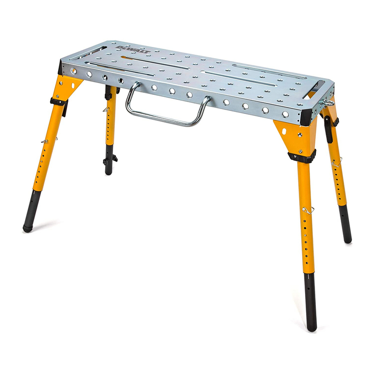
DeWalt
DeWalt DXMF4618WT instruction manual
