Tiptop Audio ECHOZ User manual

ECHOZ
ZVERB
Z5000
www.tiptopaudio.com

01
A user manual for ECHOZ ZVERB Z5000 eect modules
This user manual covers the use of the ECHOZ, ZVERB and the
Z5000 Multi Eects modules. Due to similarities in method of
operation this user manual covers all 3 modules with sections
describing the programs on each afterward.
ECHOZ - Is an FX module fully dedicated to time delay eects from
emulation of tape echoes to early digital delays to complex multi-fx
units. 24 dierent programs cover a wide range of options and
internal signal path structures.
ZVERB - Has 24 dierent types of eects available ranging from
typical reverbs to more complex eects that combine delay and
pitch shifting with reverb. The eects are grouped by decades
based on either the era an algorithm or device was introduced or the
time when the eect was most popular.
Z5000 - The Z5000 is a Multi Eects module, it provides 24 eects
that include reverbs, delays, modulation, pitch and harmonizers. The
eects in the Z5000 were carefully selected to provide both
commonly used delay and reverbs and also some unusual sounding
and experimental eects.
Hardware Features:
- 8hp
- 3 illuminated buttons for bank selections
- 8 program per bank, total 3 banks
- 3 CV inputs for all 3 DSP parameters
- Analog clocking of DSP with CV
- Black version: +12V@130mA -12V@20mA
- White version: +12V@100mA -12V@20mA

02
Let’s get started.
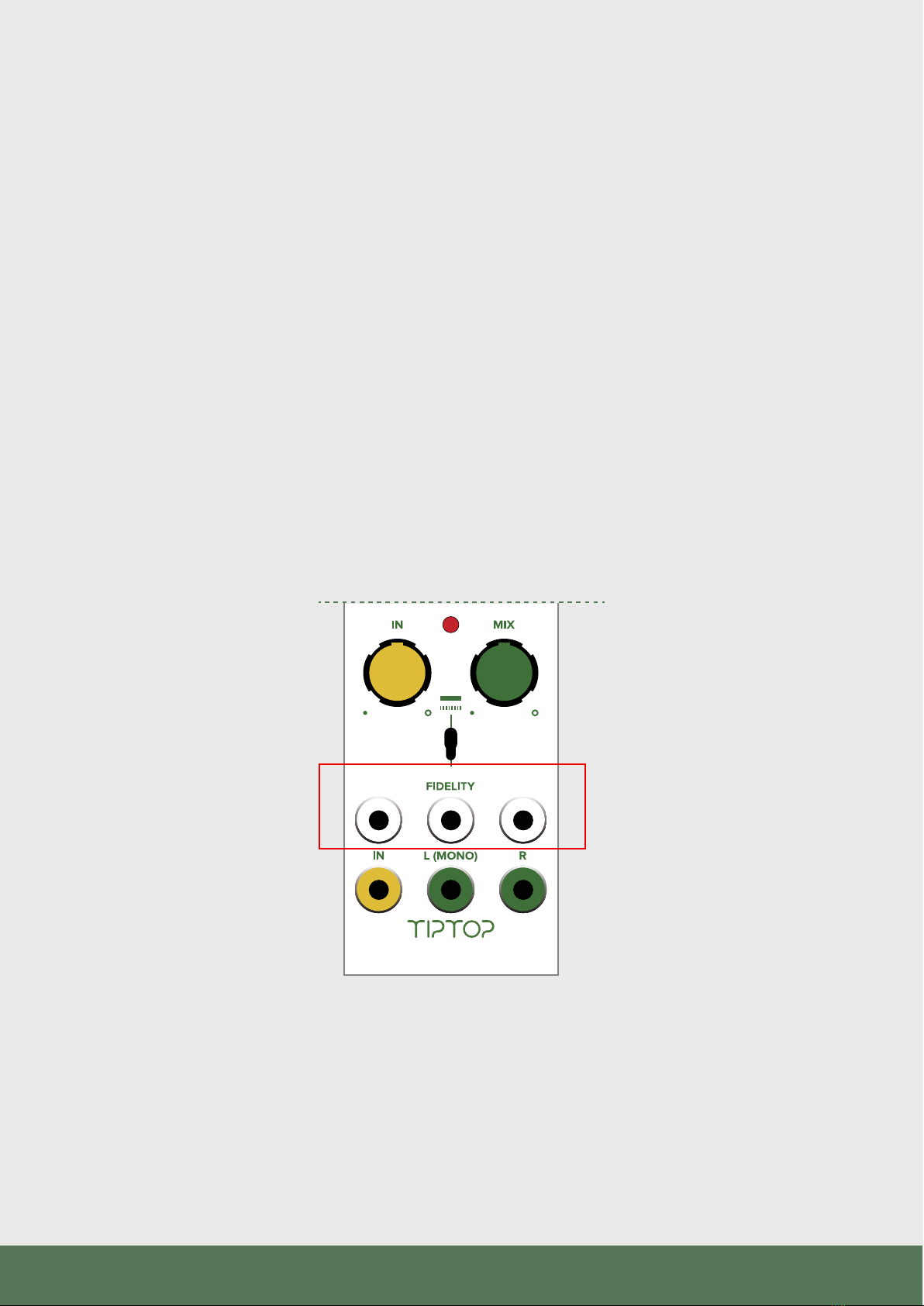
Set the Fidelity to max (CW), turn on power, patch audio into the In
jack, patch the left and right output to your sound system. Make sure
to patch both left and right so you get the full joy of stereo.
Set the following knobs to the center: MIX, IN, TIME, FILTER,
FEEDBACK/MOD.
FILTER TIME FB/MOD
TIME
FBACK/MOD
FILTER
AUDIO SOUND SYSTEM

03
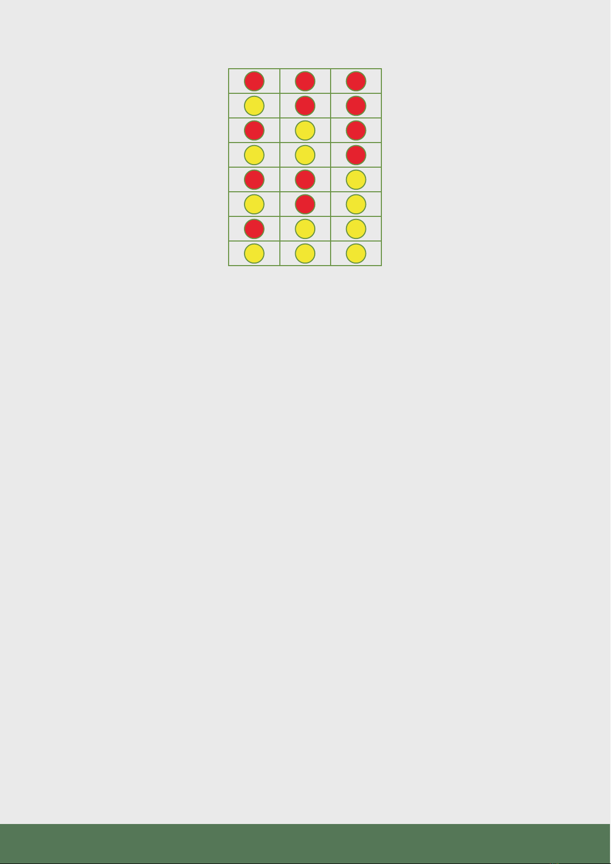
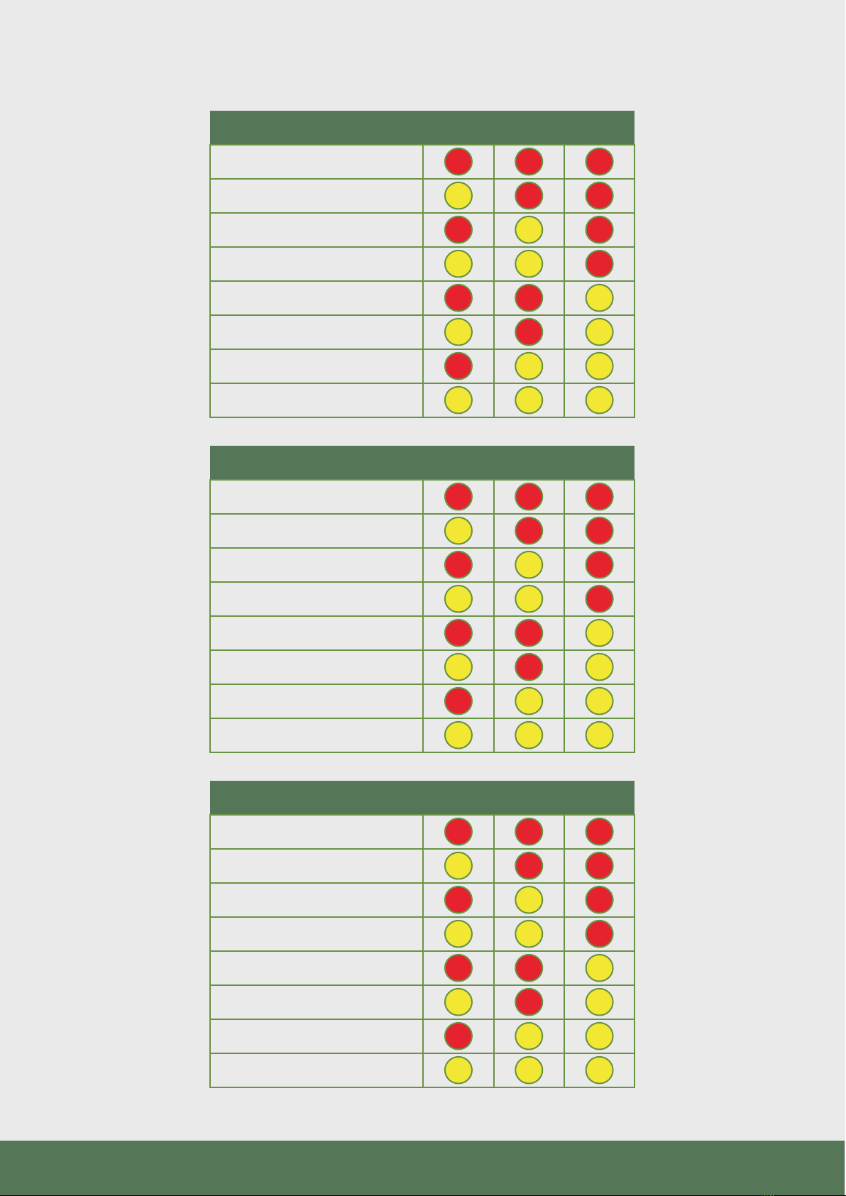
There are 3 buttons on the module, each one lets you scroll through
a bank of 8 eects. Hold down the Left button until it flashes
indicating it is loading this bank into the DSP. Now that you are in
that bank, scroll through the eight eects by clicking the left button.
You will notice that everytime you switch a program the light on the
3 buttons indicate a pattern, the pattern is there for 5 seconds and
then goes o. This light pattern can help you remember a specific
eect you liked. If the pattern light turns o and you would like to
view it again just short click one of the other two inactive bank
buttons.
FILTER TIME FB/MOD
TIME
FBACK/MOD
FILTER
04
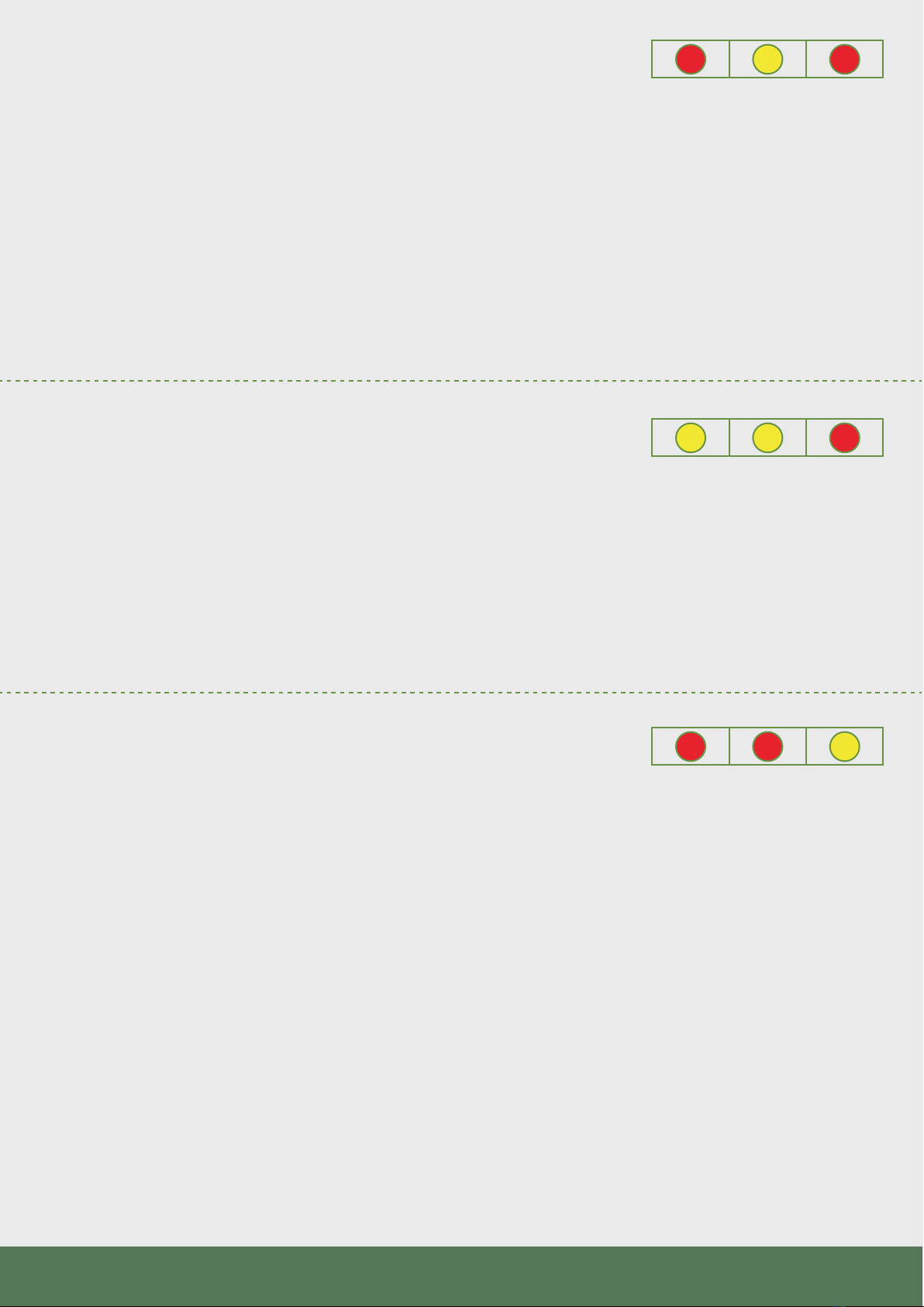
While scrolling, once you reach the YELLOW YELLOW YELLOW
pattern you know you are on eect No8, the last eect in that bank.
The bank light will also turn red. One more click and you are back to
eect No1 RED RED RED. Scrolling will continuously load the eects
in a loop 1..2..3…...7..8..1..2..3 etc.
These FX modules were designed on the concept of scrolling and
auditioning the eects live. We recommend scrolling while listening
and stop on the eect you like. The module will remember which
program you last used in a bank so when you switch between banks
you can switch between 3 of your favorite eects, one in each bank.
To switch to the next bank, just hold down the next bank button
down and a new bank will load up into the DSP.
The Eects Program section for each module has the LED patterns
for each eect. It might be useful for the first time using the module
to print or look up the table while scrolling to get familiar with the
type of eects.
1
2
3
4
5
6
7
8

05
Understanding the view modes:
The module has two dierent display modes: default and minimal.
The dierences are listed below:
Default: Shows the program number in binary when changing
programs. Also, pressing an inactive bank button shows the current
preset number. Consult the charts in the eect programs for the LED
combinations for each program. Default also remembers the last
program set in each bank, so switching from the left bank to the
middle or right bank will load the last used program in that bank. For
example, switching from Left bank program 3 to Right bank then
back to Left will recall program 3 again.
Minimal: No display of the program number as shown in the eects
program section. The bank button will be yellow for programs 1-7
and turn red at program 8. Changing a bank will load program 1 each
time. For example, changing from Left bank program 3 to Right will
load program 1 in that bank, and switching back to Left will load
program 1 again.
If you would like to change the mode:
- To select the minimal mode hold down the center button on
power up.
- To select the default mode hold down the right button on
power up.
The selected mode is stored in memory and will be recalled on
future power ups. We encourage you to try both modes and find the
one that is better for you, this is a personal preference.

06
Manual Controls:
Left Button - Hold to access the Left bank of 8 programs
Middle Button - Hold to access the Middle bank of 8 programs
Right Button - Hold to access the Right bank of 8 programs
Time knob - controls the decay time of Reverbs, the Delay time or
the rate of Modulation LFOs
Filter knob - sets the cuto frequency of the low/high or bandpass
filters in the program
FILTER TIME FB/MOD
TIME
FBACK/MOD
FILTER
Left Button
Middle Button
Right Button
FILTER TIME FB/MOD
TIME
FBACK/MOD
FILTER
Time knob
TIME
FBACK/MOD
FILTER
Filter knob
07
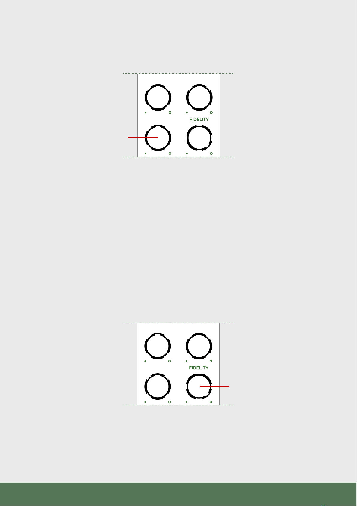
Feedback/Mod knob
Fidelity knob
Feedback/Mod knob - changes the amount of feedback in delay
programs or the depth/rate of LFOs in Reverb or Mod programs. Check
the program descriptions for details on what this controls.
Fidelity - Is a DSP manipulation technique developed originally for
the Z-DSP and brought to this line of eect modules as well. Inside
the module is an analog VCO that clocks the DSP chip, the use of an
analog clock (not a digitally generated clock) not only contributes to
the overall organic sound quality of the module, but also lets you
take the eects into new sonic territories with variation of the clock
speed. The Fidelity knob in will alter the frequency of the VCO clock
with sound eects ranging from pitch shifting and down to total
degraded digital noise.
FILTER TIME FB/MOD
TIME
FBACK/MOD
FILTER
FILTER TIME FB/MOD
TIME
FBACK/MOD
FILTER
08
CV Controls:
There are 3 CV control jacks on the module: Feedback/Mod, Time and
Filter. The left and right jacks are dedicated for controlling DSP
parameters mapped to the Mod and Filter controls, the center jack CV can
be routed with the toggle switch to either TIME which is a DSP parameter
or to Fidelity clock control.
The DSP CV controls have a built in slew circuit which limit the speed they
can be modulated. This is part of the design of the DSP chip. The Fidelity
CV is all analog and can be modulated at any speed and even into the
audio range.
In extreme cases where negative voltage CV is applied to Fidelity the DSP
chip might crash, this does not damage anything, just remove the negative
CV, switch a program and the DSP will be back in action.
FILTER TIME FB/MOD
TIME
FBACK/MOD
FILTER

09
Clipping light indicator:
The clipping light monitors the input and output signal level of the DSP
chip. If a signal level at the input or the output is too high that light will
flash. Some times due to feedback the output signal can grow much larger
than the input signal, in that case reduce the amount of Feedback with the
Feedback knob.
Output gain:
These FX modules were designed to be used mostly at the end of
your synthesizer patch. As such they provide an interface between
your modular and your standard commercial line level studio gear.
The output gain of the FX modules is lower than standard Eurorack
levels but can also be set higher than line levels. When used with
modular levels on the input and the IN knob at 50% and below the
output is closer to line level which provides an easy interface with
your studio gear without risk of clipping.
FILTER TIME FB/MOD
TIME
FBACK/MOD
FILTER
Clipping light indicator
FILTER TIME FB/MOD
TIME
FBACK/MOD
FILTER
Output gain

10
A word about your sound sources:
Every eect reacts dierently to the source sound, this can result in some
eects sounding very dull or strange if the incoming sound is not ideal for
their use.
Later sections of this user manual have detailed description of each eect
and the source material that will work with it best. Obviously, these are just
recommendations and in the spirit of the modular synthesizer going the
‘wrong’ way can often lead you to sounds you have never heard before.
Experiment!
FAQ:
Question: Are the delays on the FX modules syncable to external clock?
Answer: No, the variable clock rate of the DSP chip prevents clock sync
programs from syncing precisely.
Question: Is my last selected program saved after I turn o my modular?
Answer: Yes it is.
Question: What is the dierence between Time and Fidelity CV?
Answer: The Fidelity control changes the speed of the digital processing
sample rate. This can have a similar eect to changing the Time control of
delays but the important dierence is that Fidelity also changes the entire
processing including filter cutos, LFO speeds, etc. Lowering Fidelity will
increase the delay time of a delay but also lower the cuto of a low pass
filter and slow down an LFO modulating the delay line. The Time control
will only change the delay time of that same delay.
FILTER TIME FB/MOD
TIME
FBACK/MOD
FILTER
Sound sources
Z-DSP Zfx
Stereo In Yes No
Clock source Digital or External Internal Analog
Mix CV Yes No
VC Analog Feedback Yes No
VC Program switching Yes No
Text Display Yes No
Card Expansion Yes No (24 xed programs)
Program with NumberZ Yes No
Width 28HP 8HP

11
Question: What are the dierences between these modules and the
Z-DSP?
Answer: The Z-DSP has stereo input, VC analog feedback, CV control
over more features and a potentially unlimited number of programs
through the cards. Z-DSP is more of an eects experimentation
environment that you can even write your own eects for using NumberZ.
The Zfx line of modules are designed to add a limited well selected
number of useful eects in minimal HP.
Specifications:
+12V - 130mA (black panel) 100mA (white panel)
-12V - 20mA
+5V - 0mA
Width - 8HP
Depth - 40 mm /1.5”
CV Range - 0 - 5V
Fidelity CV Range 0 - 5V or +/-2.5V
Input Max before clipping - 12V p-p
Output Max before clipping - 8V p-p
Z-DSP Zfx
Stereo In Yes No
Clock source Digital or External Internal Analog
Mix CV Yes No
VC Analog Feedback Yes No
VC Program switching Yes No
Text Display Yes No
Card Expansion Yes No (24 xed programs)
Program with NumberZ Yes No
Width 28HP 8HP

12
Z5000
Z5000
FILTER TIME FB/MOD
TIME
FBACK/MOD
FILTER
REVERBS DELAYS PITCH
MOD
Multi Eect
Z5000
REVERBS DELAYS PITCH
MOD
FILTER TIME FB/MOD
TIME FILTER
FBACK/MOD
Multi Eect
13
FILTER TIME FB/MOD
Z5000
REVERB
Hall
Plate
80’s Verb
Gate
Room
Void
Delay > Hall
Shimmer
DELAY
Mono Digital Delay
Mono Tape Echo
Ping Pong Digital Delay
Ping Pong Tape Echo
Tape Multi-Head Blend
Diuse Band Delays
Tape Chorus
Warp Pong
PITCH/MOD
Stereo Chorus
Stereo Flanger
Vintage Ensemble
Ahhhnsemble
Formant Delay
Dual Microshift Delay
Dual Interval Delays
Detuned Taps

14
REVERB PROGRAMS FOR Z5000
Z5000 has a set of reverb algorithms specifically designed for it and
the ZVERB module. All of the programs here were developed over
several years by Tiptop R&D and take inspiration from the history of
digital reverb devices from the earliest 1970s studio rack units to 90s
high end multi-eects and 80s budget boxes.
Hall
A version of the classic 70s ‘Hall’ style reverb. This has a dark,
dense yet somewhat ‘natural’ sound. The Time control is optimized
for longer times up to several minutes.
Time - Decay time of the reverb tail
Filter - Low Pass Filter
Mod - Rate of internal modulation
Plate
The sound is brighter than ‘Hall’ with a faster attack but is also
quite dense. With lower Modulation settings a more metallic sound
is possible. The Time control is optimized for medium-sized times
up to several seconds.
Time - Decay time of the reverb tail
Filter - Low Pass Filter
Mod - Rate and intensity of internal modulation
15
80s Verb
This one comes from the 80s ‘budget’ rack units and can get
very huge and highly modulated. Probably the best choice for your
contribution to ‘Selected Ambient Works III’.
Time - Decay time of the reverb tail
Filter - Low Pass Filter
Mod - Rate and intensity of internal modulation
Gate
A gated version of the Plate algorithm. Party like it’s 1985!
Time - Decay time of the reverb tail
Filter - Low Pass Filter
Mod - Rate and intensity of internal modulation
Room
Room with early reflections and minimal coloration at low Time
settings. Can become decently large with increased Time and the
Mod gets very wobbly at high settings just for fun.
Time - Decay time of the reverb tail
Filter - Low Pass Filter
Mod - Rate and intensity of internal modulation

16
Void
Backwards, inverse sounding eect that gets pretty huge at
longer Time settings.
Time - Decay time of the reverb tail
Filter - Low Pass Filter
Mod - Rate and intensity of internal modulation
Delay > Hall
A 500ms modulatable mono delay line feeds into the Hall
algorithm. The Feedback/Mod control adjusts the delay time and
the Time parameter increases both the delay line feedback and the
decay time of the Hall.
Time - Decay time of the reverb tail + delay feedback
Filter - Low Pass Filter
Mod - Delay time + delay feedback
Shimmer
An octave up pitch shifter in the reverb creates the classic
‘shimmer’ tone. The Feedback/Mod control adjusts how much of the
pitch shifted sound is present. Setting the pitch level higher with
smaller decay Time settings will increase the pitch level and have it
come in sooner. At longer decay Time settings very high pitch level
can overload the internal loop and clip the outputs!
Time - Decay time of the reverb tail
Filter - Low Pass Filter
Mod - Amount of octave up pitch shift in the reverb tank

17
Delay Programs for Z5000
The Z5000 Delay programs come from many years of development
of the Z-DSP cards. Most of the programs in this set began life on
the Z-DSP and are chosen to give a wide range of options from basic
mono digital and tape delays to complex multi-taps.
Mono Digital Delay
Basic mono digital delay line with a low pass filter in the
feedback loop. The delay time can be modulated without glitching
and produces an FM type eect. At max feedback the sound will
loop for a long time but also slightly degrade over time.
Time - delay time
Filter - cuto of lowpass filter
Feedback - amount of feedback into the delay line
Mono Tape Echo
Mono Tape Echo program with a bandpass filter and tape
saturation in the feedback loop. Feedback is also overdriven to get
some of the runaway oscillations found in real tape machine echo
boxes.
Time - delay time
Filter - cuto of bandpass filter
Feedback - amount of feedback into the delay line

18
Ping Pong Digital Delay
Dual delay lines move the delayed sound from left to right and
back. A lowpass filter in the feedback path tapers the high end of
the repeats.
Time - delay time
Filter - cuto of lowpass filter
Feedback - amount of feedback into the delay line
Ping Pong Tape Echo
Tape Echo version of a stereo Ping Pong algorithm.
Time - delay time
Filter - cuto of bandpass filter
Feedback - amount of feedback into the delay line
Tape Multi-Head Blend
Three tape ‘heads’ each with dierent delay times feed the
Filter blend control. At the center all three taps are mixed in the
output while only two are present at the extreme left and right
settings. All of the heads heard in the output are fed back.
Time - delay time
Filter - mix of heads 1, 2 and 3. Mid point has all 3
Feedback - amount of feedback into the delay line

19
Diuse Band Delays
A delay line with six taps each run through a dierent band pass
filter. The taps are useful rhythmic ratios (1:1, 1:2, 3:4, etc). The
feedback loop has diusion to wash out the repeats over time.
Time - Delay time
Filter - adjusts modulation and diusion parameters
Feedback - amount of feedback into the delay line
Tape Chorus
A mono Tape Echo feeds a stereo Chorus. The Filter control
also changes the rate of the Chorus modulation: lower cuto is a
slower LFO and the speed increases as the filter cutos do as well.
Time - delay time
Filter - cuto of bandpass filter and rate of chorus
Feedback - amount of feedback into the delay line
Warp Pong
A stereo ping pong delay using the Tape Echo algorithm but
with a warping to the speed of the tape. The Filter control also
influences the warping speed a little bit.
Time - delay time
Filter - cuto of bandpass filter
Feedback - amount of feedback into the delay line
This manual suits for next models
2
Table of contents
Other Tiptop Audio Recording Equipment manuals


