Simrad B&G H1000 User manual

universal interfacebox
installation
IS-2509-02
www.bandgservice.co.uk

CE Certification:
This equipment generates, uses, and can radiate radio frequency energy and, if not installed and used in
accordance with the instructions, may cause harmful interference to radio communications. However, there is no
guarantee that interference will not occur in a particular installation. If this equipment does cause harmful
interference, the user is encouraged to try to correct the interference by relocating the equipment or connecting
the equipment to a different circuit. Consult an authorised dealer or other qualified technician for additional help
if these remedies do not correct the problem.
This device meets requirements for CFR47 Part 15 of the FCC limits for Class B equipment.
The h1000 meets the standards set out in European Standard EN 60945: 1997 IEC 945: 1996 for maritime
navigation and radiocommunication equipment and systems.
www.bandgservice.co.uk

trademark
All rights reserved. No part of this manual may be reproduced or transmitted in any form or by any means
including photocopying and recording, without the express written permission of B&G.
Information in this document is subject to change without notice. B&G reserves the right to change or improve its
products and to make changes in the content without obligation to notify any person or organisation of such
changes.
technical specifications
Dimensions: 70mm x 135mm x 35mm
Power Supply: 12V dc nominal (10V to 16V) via Fastnet2
Current Consumption: 50mA typical
Operating Temperature range: 0°C to +55°C
Storage Temperature range: -25°C to +70°C
Humidity: Up to 95% RH
www.bandgservice.co.uk

system connections
connections
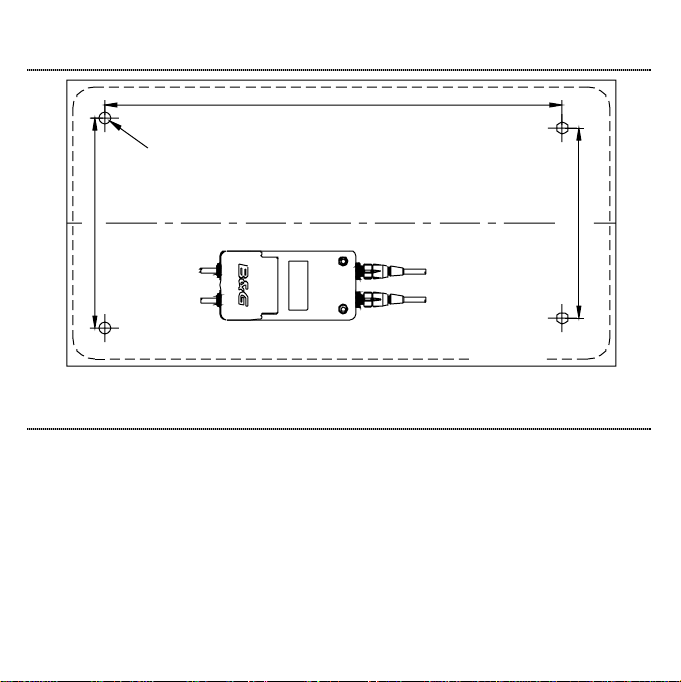
System components share data together via a common Fastnet2
databus and are supplied with bayonet connectors for ease of
installation. A selection of cable lengths are available with options for
straight and right angle connectors to suit most requirements.
To prevent the occurrence of voltage drops on larger systems, the
power supply to the system should either be placed mid-way or at both
ends of the Fastnet2databus. To connect power to the mid-point of the
system, it is recommended that the 4-Way Hub be used. The 4-Way
Hub offers two advantages. The first advantage is that it offers a
convenient entry point for power onto the system. The second
advantage is that it conveniently allows the system to be branched to
reduce the overall length of the system. The correct selection of
Fastnet2cable will negate the need for any plugs to be removed from
the system and ensure years of faultless operation.
NMEA interface
The National Marine Electronics Association (NMEA) is an organisation that has defined a number of standard
specifications for the interconnection of marine electronic instruments. These standards specify the electrical
signals and the format of the data that is transferred. This allows equipment such as the h1000 to communicate
with other manufacturers’ equipment.
The Universal Interface is an NMEA interface specifically designed to allow the h1000 system to “talk” with other
manufacturers’ equipment. The most likely devices that will be connected to the Universal Interface are position
fixers such as GPS’s and Chart Plotters. The connection of navigational data to the h1000 Instrument allows this
data to be displayed on the system and creates new calculated functions such as tide rate and direction.
The Universal Interface has one NMEA Input Port (receive) and one NMEA Output Port (transmit) and is
designed to comply with the latest NMEA 0183 standards. The Universal Interface also contains the connections
for an external alarm output. The individual NMEA sentences may be ‘Enabled’* or ‘Disabled’* as required from
the ‘Remote unit setup’ options in the ‘System’ menu of any h1000 Digital display connected to the system.
*Minimum software required: h1000-DSP – r2.05
h1000-UNI – r2.04
12V Power
Cable
HUB
Fastnet
2
Cable
Fastnet
2
Cable
Fastnet
2
Cable
www.bandgservice.co.uk

supported NMEA sentences (v2.40)
NMEA input (received) summary
NMEA Sentence Message Description
APB Heading/Track Controller (Autopilot) Sentence “B”
DBT Depth Below Transducer
DPT Transducer Depth and Offset
GGA Global Positioning System Fix Data
GLL Geographic Position, Latitude and Longitude
GSA GNSS DOP and Active Satellites
GSV GNSS Satellites in View
HDG Heading Magnetic, Deviation and Variation
MWD Wind Direction and Speed (TWD °M / °T and TWS)
MWV Wind Speed and Angle (AWS and AWA, flag set to R)
RMB Recommended minimum navigation information
RMC Recommended minimum specific GNSS data
VHW Water Speed and Heading (°M / °T)
VTG Course Over Ground and Speed Over Ground
ZDA Tim e and Date
ZTG UTC and Time to Destination Waypoint
www.bandgservice.co.uk

supported NMEA sentences (v2.40), continued
B&G proprietary NMEA input (received) summary
NMEA Sentence Message Description
PBGTTBS Polar speed (knots)
PBGTLAY Distance and Time to Lay-Line
PBGTVMG Angle for best VMG upwind (polar)
Upwind heading for best VMG (polar)
Downwind heading for best VMG (polar)
NMEA output (transmitted) summary
NMEA Sentence Message Description
DPT Transducer Depth and Offs et
GGA Global Positioning System Fix Data
GLL Geographic Position, Latitude and Longitude
HDG Heading Magnetic, Deviation and Variation
HDM Heading, Magnetic
HDT Heading, True
MT W Water Temperature, °C
MWD Wind Direction and Speed (TWD °M / °T and TWS)
MWV Wind Speed and Angle (AWS and AWA, flag set to R)
RMB Recommended minimum navigation information
RMC Recommended minimum specific GNSS data
VHW Water Speed and Heading (°M / °T)
VLW Distance Travelled through the Water
VTG Course Over Ground and Speed Over Ground
www.bandgservice.co.uk

selectable NMEA
The Selectable NMEA feature allows control over which sentences are received and transmitted by the h1000
Universal Interface. This gives flexibility when interfacing to other manufacturers’ products such as radars and
chart-plotters. Selectable NMEA allows you to filter out unwanted NMEA messages and prevents duplicated data
on the system.
3rd Party
Pilot
3rd Party
GPS
3rd Party Radar
Plotter/GPS
h1 00 0-U NI
h1 00 0-U NI
h1000
System
Instrument
NMEA
Senten ces
GPS NMEA
Sentences
GPS + Instrument
NMEA Sentences
Configuring Selectable NMEA
Identify the Universal Interface Box you wish to configure, this is identified by the first three digits of the serial
number found on the printed label located inside the lid of the interface box. Select the chosen box from the list
displayed, select either NMEA I n or NM EA Out. The options available are detailed as follows:
Selecting NMEA Input sentences – ‘Current Input’ - Press ENT ER to s elect, press ENT ER again and scroll
through the listed sentences, press ENT ER to view the options. Press ENT ER and scroll to either On or Off,
press EN T ER to make your selection. Scroll to OK to return to the listed sentences. Repeat the operation until
you have made all your selections.
Selecting NMEA Output sentences – ‘Current Output’ - Follow the same procedure as detailed above.
Renaming the interface box – ‘Name’ - Press ENT ER to re-name the interface box (if required), use the
UP/DOWN arrow keys to select the number or letter required (maximum 10 characters), once you have
completed your name change scroll to, and highlight OK, press ENTER to return to the Remote units screen.
www.bandgservice.co.uk

electrical connections
5
2 3
41
Front view of
male connector pins
external connections
Two Fastnet² connectors are provided on the top of
the unit. These connectors allow connection to the
rest of the system for the supply of power and data.
The table below shows pin functions.
Pin
Number Signal
112V
2Busy
3Fastnet²-
4Fastnet²+
50V
GROMMET
CABLE TIE
Push the cable(s) through the grommet so that the
outer insulation shows beyond the grommet and
s ecure us ing a cable tie as s hown in the d iagram
opposite
www.bandgservice.co.uk

electrical connections
NMEA TX+
NMEA TX-
NMEA SCN
NMEA RX-
NMEA RX+
SCREEN
RED +
No CONN.
No CONN.
BLUE -
12345678910
ALARM
NMEA
UNIVERSAL
internal connections
Wire the cables into the interface box as shown in the
diagram opposite.
method
To open the connector, carefully push a small flat
headed terminal screwdriver into the slot directly above
the relevant terminal number.
Push the bare end of the wire into the terminal
connector and withdraw the screwdriver.
Note: The maximum sink current for any alarm
connected to this interface box is 18mA.
www.bandgservice.co.uk

installation
53mm
ORIENTATION
48mm
113.1mm
BGM014062
BOX BASEOUTLINE
Drill4 offholes
(2.9mmØ)for
No.6 x 3/4" self
tapping screws
WARNING: THIS DRAWING IS NOT TO SCALE
Use the Installation instructions and the template provided with the unit packaging to install the Interface Box.
www.bandgservice.co.uk
Table of contents
Other Simrad Recording Equipment manuals
Popular Recording Equipment manuals by other brands

Alber
Alber neodrives SimplyRemote user manual

ACS
ACS AET63 BioTRUSTKey Reference manual

Yamaha
Yamaha YRM-103 owner's manual

Wirepath Surveillance
Wirepath Surveillance WPS-100-NVR-4IP Installation and user manual

DINUY
DINUY KNX EM KNT 002 Installation and commissioning

uher
uher VARIOCORD 23 Service manual