TitanTec TT-BV3405 User manual

TT-BV3405
For technical support in the UK please contact Sherpa Tools on 01522 283020.

SAFETY FIRST
Instructions contained in warnings within this
manual marked with a symbol concern
critical points which must be taken into
consideration to prevent possible serious bodily
injury, and for this reason you are requested to
read all such instructions carefully and follow
them without fail.
■WARNINGS IN THE MANUAL
WARNING
This mark indicates instructions which must be
followed in order to prevent accidents which
could lead to serious bodily injury or death.
IMPORTANT
This mark indicates instructions which must be
followed, or it leads to mechanical failure,
breakdown, or damage.
NOTE
This mark indicates hints or directions useful in
the use of the product.
CONTENTS
1. Introduction …………………………………………………………………………………………………………...……………………… 2
2. Identification of Symbols ................................................................................................................……3
3. General Safety Precautions ………………………………………………………………………………………………………….…
4. Identification ……………………………………………………………………………………………..……...........................…. 5
5. Assembly ................……………………………………………………................……………………………………………………6
6. …………………………………………………………………….........…………………………………………………………8
7. Maintenance …………………………………………………………………….……………………………………………………………10
8. Storage ………………………………………………………………..………………………………………………………………………12
9. Troubleshooting Table ………………………………………………………........……………………………………………………13
10. Technical Data ……………………………………………………………………..………………………………………………………13
Operation
3
-- 3 --
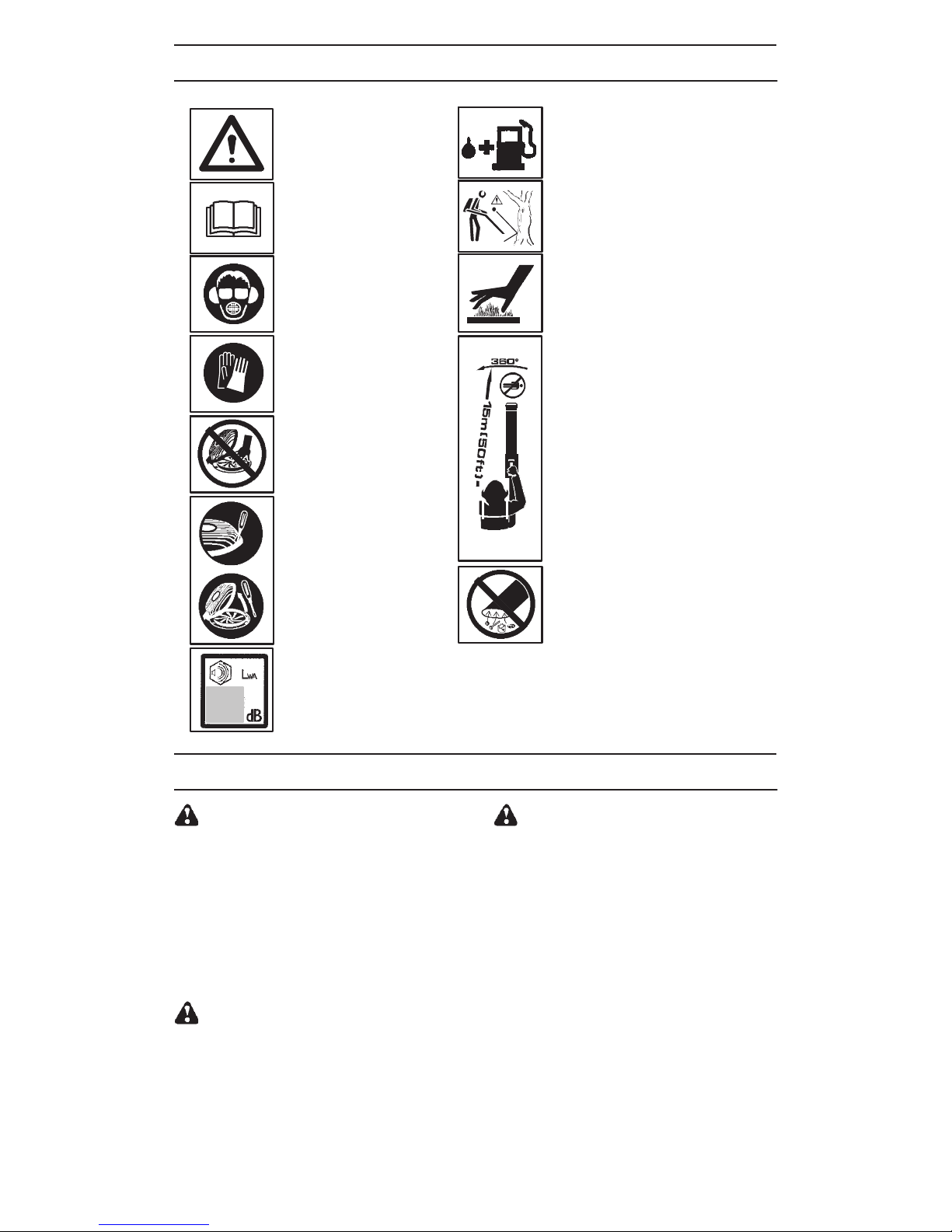
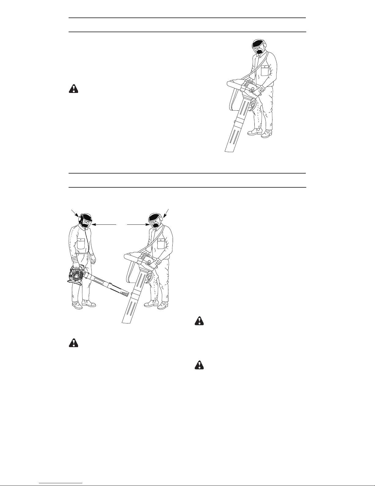
IDENTIFICATION OF SYMBOLS
Approved protective goggles
or visor, ear protection, and
face mask in dusty environments
must be worn.
The blower operator must make sure
that no bystanders or animals come
nearer than 15 metres.
Whenever several operators are
working in the same work area, they
should maintain a safe distance of at
least 15 meters from one another.
WARNING: The muffler is very
hot during and after use. Do not
touch the muffler, muffler guard, or
surrounding surfaces, or allow
combustible material such as dry
grass or fuel to do so.
Always wear approved,
protective gloves.
Instructions on how to open
vacuum inlet cover. Gently tilt
the handle of the screwdriver
toward the front of the unit to
release the latch while pulling
up on the vacuum inlet cover
with your other hand.
WARNING: This blower
can be dangerous! Careless
or improper use can
cause serious or even fatal
injury.
Read and understand the
instruction manual before
using the blower.
WARNING: Be sure the
bottom cover is secured or
the vacuum tube is properly
installed. Avoid the impeller
blade with your hand or any
foreign object.
Sound power
level
stroke oil.
WARNING: The blower may throw
objects at high velocity that can
ricochet and hit the operator. This
may cause serious eye damage.
When using the vacuum attachment, the
unit is designed to pick up dry material
such as leaves, grass, small twigs, and
bits of paper. Do not vacuum stones,
gravel, metal, broken glass, etc., to
avoid severe damage to the impeller.
GENERAL SAFETY PRECAUTIONS
WARNING: Failure to follow all
Safety Rules and Precautions can result in
serious injury.
KNOW YOUR UNIT
SRead your instruction manual carefully until
you completely understand and can follow all
warnings and safety rules before operating
the unit.
DRestrict unit to users who understand and will
follow all warnings and safety rules in this
manual.
WARNING: Inspect area before start-
ing unit. Remove all debris and hard objects
such as rocks, glass, wire, etc. that can rico-
chet, be thrown, or otherwise cause injury or
damage during operation.
WARNING: While vacuuming or
blowing debris, hold the unit with the muffler
side facing away from your body and clothes.
Use your unit as a blower for:
DSweeping debris or grass clippings from
driveways, sidewalks, patios, etc.
DBlowing grass clippings, straw, or leaves into
piles, around joints, or between bricks.
Use your unit as a vacuum for:
DPicking up dry material such as leaves, grass,
small twigs, and bits of paper.
DFor best results during vacuum use, operate
your unit at high speed.
DMove slowly back and forth over the material
as you vacuum. Avoid forcing the unit into a
pile of debris as this can clog the unit.
DKeep the vacuum tube about an inch above
the ground for best results.
Use unleaded petrol and two

-- 4 --
GENERAL SAFETY PRECAUTIONS
PLAN AHEAD
WARNING: This machine produces
an electromagnetic field during operation. Under
some circumstances, this field may interfere
with active or passive medical implants. To re-
duce the risk of serious or fatal injury, we recom-
mend persons with medical implants to consult
their physician and the medical implant
manufacturer before operating this machine.
DAlways wear eye and ear protection when
operating, servicing, or performing
maintenance on unit. Wearing eye protection
will help to prevent rocks or debris from being
blown or ricocheting into eyes and face which
can result in blindness and/or serious injury.
Eye protection should be marked Z87.
DAlways wear foot protection. Do not go
barefoot or wear sandals.
DAlways wear respirator or face mask when
working with unit in dusty environments.
DSecure hair above shoulder length. Secure or
remove jewelry, loose clothing, or clothing
with loosely hanging straps, ties, tassels, etc.
They can be caught in moving parts.
DDo not operate unit when you are tired, ill,
upset, or if you are under the influence of
alcohol, drugs, or medication.
DKeep children, bystanders, and animals away
from work area a minimum of 15 meters when
starting or operating unit. Do not point blower
nozzle in the direction of people or pets.
HANDLE FUEL WITH CAUTION
DEliminate all sources of sparks or flame
(including smoking, open flames, or work that
can cause sparks) in the areas where fuel is
mixed, poured, or stored.
DMix and pour fuel in an outdoor area; store
fuel in a cool, dry, well ventilated place; use an
approved, marked container for all fuel
purposes.
DDo not smoke while handling fuel or while
operating the unit.
DMake sure the unit is properly assembled and
in good operating condition.
DDo not fill fuel tank while engine is hot or
running.
DAvoid spilling fuel or oil. Wipe up fuel spills
before starting engine.
DMove at least 3 meters away from fuel and
fueling site before starting engine.
DAlways store petrol in a container approved
for flammable liquids.
OPERATE YOUR UNIT SAFELY
WARNING: Stop the engine before
opening the vacuum inlet door. The engine
must be stopped and the impeller blades no
longer turning to avoid serious injury from the
rotating blades.
WARNING: While vacuuming or
blowing debris, hold the unit with the muffler
side facing away from your body and clothes.
DThis garden blower/vacuum is only designed
for blowing away or removal of leaves and
other debris on the ground.
DInspect unit before each use for worn, loose,
missing, or damaged parts. Do not use until
unit is in proper working order.
DKeep outside surfaces free of oil and fuel.
DNever start or run engine inside a closed
room or building. Breathing exhaust fumes
can kill.
DMufflers fitted with catalytic converters get
very hot during use and remain so for some
time after stopping. This also applies at idle
speed. Contact can result in burns to the skin.
Remember the risk of fire!
DTo avoid static electricity shock, do not wear
rubber gloves or any other insulated gloves
while operating unit.
DDo not set unit on any surface except a
clean, hard area while engine is running.
Debris such as gravel, sand, dust, grass,
etc. could be picked up by the air intake and
thrown out through discharge opening,
damaging unit, property, or causing serious
injury to bystanders or operator.
DAvoid dangerous environments. Do not use in
unventilated areas or where explosive vapors
or carbon monoxide build up could be
present.
DDo not overreach or use from unstable
surfaces such as ladders, trees, steep
slopes, rooftops, etc. Keep firm footing and
balance at all times.
DNever place objects inside the blower tubes;
always direct the blowing debris away from
people, animals, glass, and solid objects such
as trees, automobiles, walls, etc. The force of
air can cause rocks, dirt, or sticks to be
thrown or to ricochet which can hurt people or
animals, break glass, or cause other damage.
DNever run unit without the proper equipment
attached. When using your unit as a blower,
always install blower tubes. When using your
unit as a vacuum, always install vacuum
tubes and vacuum bag assembly. Make sure
vacuum bag assembly is completely zipped.
DCheck air intake opening, blower tubes,
vacuum tubes, and elbow tube frequently,
always with engine stopped and spark plug
disconnected. Keep vents and discharge
tubes free of debris which can accumulate
and restrict proper air flow.
DNever place any object in the air intake
opening as this could restrict proper air flow
and cause damage to the unit.
DNever use for spreading chemicals, fertilizers,
or other substances which may contain toxic
materials.
DTo avoid spreading fire, do not use near leaf or
brush fires, fireplaces, barbecue pits,
ashtrays, etc.
DUse only for jobs explained in this manual.
MAINTAIN YOUR UNIT PROPERLY
DHave all maintenance other than the
recommended procedures described in the
instruction manual performed by an
authorise service dealer.

*(1(5$/ 6$)(7< 35(&$87,216
-'LVFRQQHFW VSDUN SOXJ EHIRUH SHUIRUPLQJ
PDLQWHQDQFH H[FHSW IRU FDUEXUHWRU
DGMXVWPHQWV
-
PHQW SDUWV XVH RI DQ\ RWKHU SDUWV PD\ YRLG
\RXU ZDUUDQW\ DQG FDXVH GDPDJH WR \RXU XQLW
-(PSW\ IXHO WDQN EHIRUH VWRULQJ WKH XQLW 8VH
XS IXHO OHIW LQ FDUEXUHWRU E\ VWDUWLQJ HQJLQH DQG
OHWWLQJ LW UXQ XQWLO LW VWRSV
-'R QRW XVH DQ\ DFFHVVRU\ RU DWWDFKPHQW
RWKHU WKDQ WKRVH UHFRPPHQGHG E\
PDQXIDFWXUHU IRU XVH ZLWK \RXU XQLW
-'R QRW VWRUH WKH XQLW RU IXHO LQ D FORVHG DUHD
ZKHUH IXHO YDSRUV FDQ UHDFK VSDUNV RU DQ
RSHQ IODPH IURP KRW ZDWHU KHDWHUV HOHFWULF
PRWRUV RU VZLWFKHV IXUQDFHV HWF
-6WRUH LQ D GU\ DUHD RXW RI UHDFK RI FKLOGUHQ
-6HFXUH WKH PDFKLQH GXULQJ WUDQVSRUW
6$)(7< 127,&( ([SRVXUH WR YLEUDWLRQV
KDQG WRROV FRXOG FDXVH EORRG YHVVHO RU QHUYH
GDPDJH LQ WKH ILQJHUV KDQGV DQG MRLQWV RI SHR
SOH SURQH WR FLUFXODWLRQ GLVRUGHUV RU DEQRUPDO
VZHOOLQJ 3URORQJHG XVH LQ FROG ZHDWKHU KDV
EHHQ OLQNHG WR EORRG YHVVHO GDPDJH LQ RWKHU
ZLVH KHDOWK\ SHRSOH ,I V\PSWRPV RFFXU VXFK DV
QXPEQHVV SDLQ ORVV RI VWUHQJWK FKDQJH LQ VNLQ
FRORU RU WH[WXUH RU ORVV RI IHHOLQJ LQ WKH ILQJHUV
KDQGV RU MRLQWV GLVFRQWLQXH WKH XVH RI WKLV WRRO
DQG VHHN PHGLFDO DWWHQWLRQ $Q DQWLYLEUDWLRQ
V\VWHP GRHV QRW JXDUDQWHH WKH DYRLGDQFH RI
WKHVH SUREOHPV 8VHUV ZKR RSHUDWH SRZHU WRROV
RQ D FRQWLQXDO DQG UHJXODU EDVLV PXVW PRQLWRU
FORVHO\ WKHLU SK\VLFDO FRQGLWLRQ DQG WKH FRQGLWLRQ
RI WKLV WRRO
,'(17,),&$7,21 :+$7 ,6 :+$7"
:+$7 ,6 :+$7"
6WDUWHU
9DFXXP KDQGOH
)XHO WDQN
3ULPHU EXWWRQ
9DFXXP KDQGOH
)XHO WDQN
3ULPHU EXWWRQ
3ULPHU EXWWRQ
1.Starter
2.Vacuum handle
3.Fuel tank
4.Primer button
5.Choke lever
6.Spark plug
7.Throttle trigger
8.Stop switch
9. Upper blower tube
10.Lower blower tube
11.Lower vacuum tube
12.Nut
14.Upper vacuum tube
15.Elbow tube
16.Vacuum bag
Use only recommended replace-
TITAN
WKURXJK SURORQJHG XVH RI SRZHUHG
petrol
13.Bolt
Tool kit bag
Mix Bottle
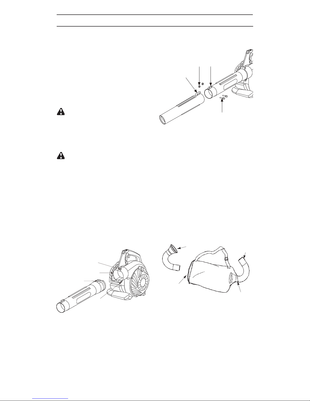
Blower Outlet
Rib
Rib
Rib
Nut
Bolt
5. Secure the tube by turning the bolts clock-
( up-right )
Clamp Bolt
( upper )
Clamp Bolt
( lower )
The tube clamp bolts must be loose
the clamp bolt ( upper ) in the blower outlet;
slide the tube into place.
5. Secure the tube by turning the bolts clock-
2. Secure the tube by turning the bolts clock-
wise
3. Align the rib on the lower blower tube
with the rib on the upper blower tube.
● Blower
● Upper blower tube
● Lower blower tube
● Elbow tube
● Vacuum bag
● Upper Vacuum tube
● Lower Vacuum tube
● Tool kit bag
● Mix Bottle
2. Secure the tube by turning the bols clock-
wise
3. Align the rib on the lower blower tube
with the rib on the upper blower tube.
4. Slide the lower blower tube onto the upper
blower tube.
5. Secure the tube by turning the bolts clock-
wise.
6. To remove the tubes, turn the bolt counter-
clock wise toloosen the tubes.
Clamp Bolt
(upper)
Nut Rib
Rib
Bolt
Blower Outlet
Rib
(Up-right)
Clamp Bolt
(lower)
Tool kit bag
Mix Bottle
Blower Outlet
Rib
Rib
Rib
Nut
Bolt
5. Secure the tube by turning the bolts clock-
( up-right )
Clamp Bolt
( upper )
Clamp Bolt
( lower )
The tube clamp bolts must be loose
the clamp bolt ( upper ) in the blower outlet;
slide the tube into place.
5. Secure the tube by turning the bolts clock-
2. Secure the tube by turning the bolts clock-
wise
3. Align the rib on the lower blower tube
with the rib on the upper blower tube.
BOX
box
anti-
clockwise
Rib
(up-right)
Clamp Bolt
( upper )
Clamp Bolt
( Lower )
Blower Outlet
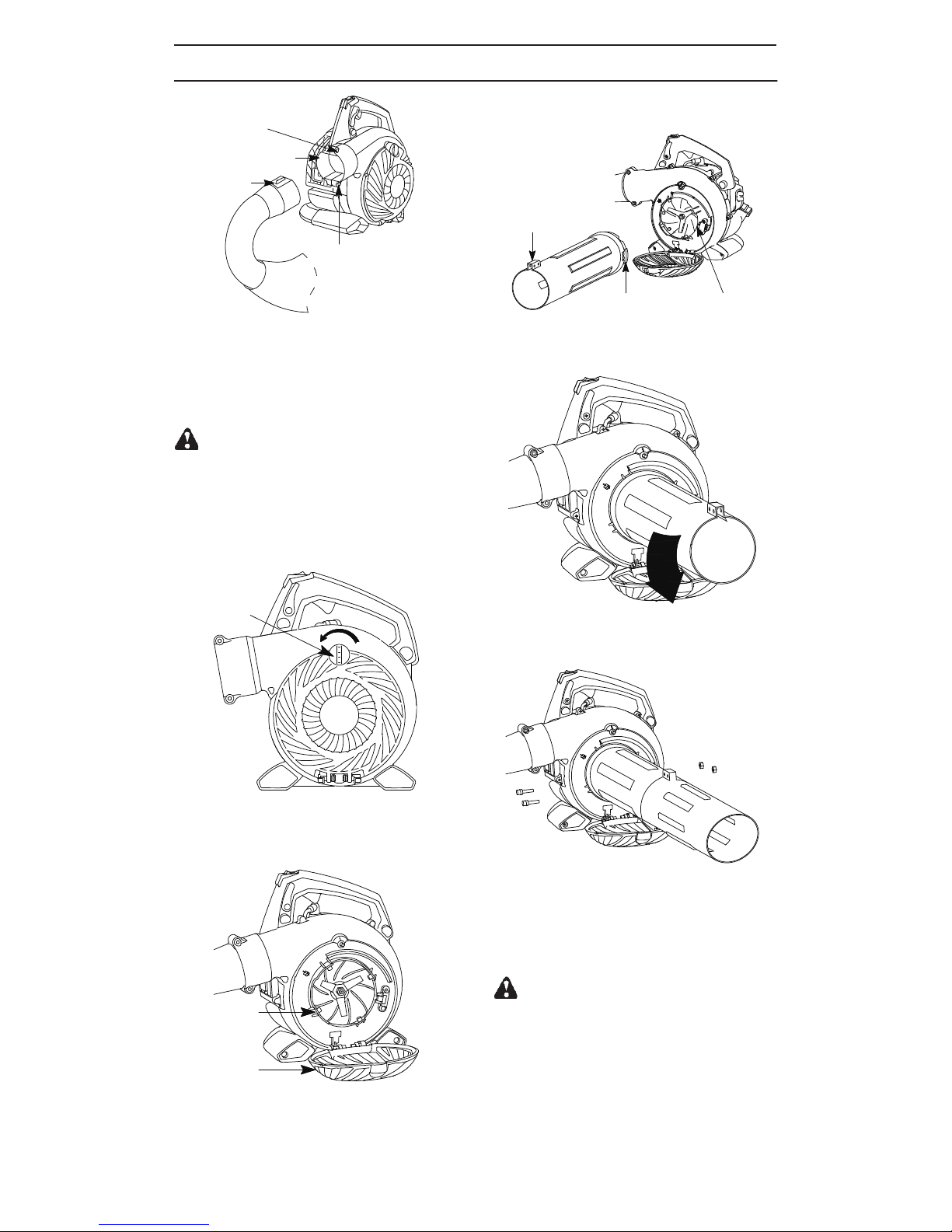
the blower outlet clamp bolt (upper).
6. Secure the elbow tube by turning the bolts
clockwise.
Knob
knob loosed completely.
2. Pulling up the vacuum inlet cover with your hand.
4. Align the switch on the inside of the vacuum
inlet with the slot on the upper vacuum tube.
side switch
slot
rib( up-right )
5. Push the upper vacuum tube into the vac-
uum inlet. Turn the tube counterclockwise
to secure the tube to the blower unit.
6. Align the rib on the lower blower tube
with the rib on the upper blower tube. Sli-
de the lower vacuum tube on to the upper
vacuum tube.
assemble the two tubes together with
the supplied screws.
1. Remove the elbow tube and vacuum bag
Clamp Bolt
(upper)
rib(up-right)
slot side switch
Clamp Bolt
(Lower)
Blower Outlet
Knob
Vacuum Inlet
Vacuum
Inlet
Cover
Rib
(up-right)
Knob loosed completely.
2. Pulling up the vacuum inlet cover with your
hand.
3. Hold the vacuum inlet cover open until up-
per vacuum tube is installed.
5. Push the upper vacuum tube into the vacu-
secure the tube to the blower unit.
6. Align the rib on the lower blower tube with
the rib on the upper blower tube. Slide the
lower vacuum tube on to the upper vacuum
tube.
ssemble the two tubes together with the s-
upplied screws.
4. Align the switch on the inside of the vacuum
inlet with the slot on the upper vauum tube.
anticlockwise
1. Turning the knob till the
um inlet. Turn the tube to
anticlockwise
by turning the bolts to lo
anticlockwise osen
the elbow tube.
7. When vacuum tubes are fitted together a-
Eye
protection
Blower Vacuum
authorise
2-stroke

starter
primer bulb
choke level
1. Slide the self-lock to non-integrated state.
2. Move the stop switch to "1" position.
3. Slowly press the primer bulb 6 times.
Blower
choke level
primer bulb
starter
Vacuum
2. Move the stop switch to “1” position.
3. Slowly press the primer bulb 6 times.
1. Ensure the throttle lock lever is in the vertical
position.

4. Move the choke lever to the "OFF" choke
position
5. Pull starter rope handle sharply until engine
6. Squeeze the throttle trigger, the choke lever
7. Pull starter rope sharply until engine runs.
8. Once the engine runs, allow it to run 10 se-
conds;
1. Slide the self-lock to non-integrated state.
2. Move the stop switch to "1" position.
3. Push starter rope sharply until engien runs.
Stop Switch
Self-lock
osition.
5. Pull starter rope handle sharply until engine
sounds as if it is trying to start, but do not p-
ull rope more than 6 times
8. Once the engine runs, allow it to run 10 se-
conds.
2. Move the stop switch to “1” position.
3. Push starter rope sharply until engine runs.
STARTING A WARM ENGINE
Stop Switch
Air Filter
Cover
Air Filter
position.
1. Ensure the throttle lock lever is in the vertical
4. Move the choke lever to the “Full” choke p-
will move to “ ” choke position.
RUN
6. Squeeze the throttletrigger, the choke lever
7. Pull starter rope sharply until engine runs.
authorise
Throttle lock
lever
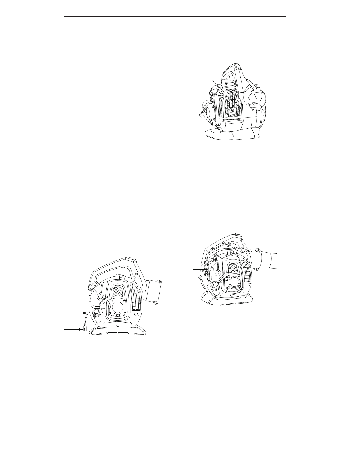
Fuel Line
Muffler
Mounting
Screw
Idle Speed Screw
Air
Filter
Cover
Fuel Filter
petrol
anticlockwise
authorise

-- 12 --
STORAGE
WARNING: Prepare unit for storage at
end of season or if it will not be used for 30 days
or more.
SAllow engine to cool, and secure the unit be-
fore storing or transporting.
SStore unit and fuel in a well ventilated area
where fuel vapors cannot reach sparks or
open flames from water heaters, electric mo-
tors or switches, furnaces, etc.
SStore unit with all guards in place. Position unit
so that any sharp object cannot accidentally
cause injury.
SStore unit and fuel well out of the reach of chil-
dren.
EXTERNAL SURFACES
SIf your unit is to be stored for a period of time,
clean it thoroughly before storage. Store in a
clean dry area.
SLightly oil external metal surfaces.
INTERNAL ENGINE
SRemove spark plug and pour 1 teaspoon of
spark plug opening. Slowly pull the starter
rope 8 to 10 times to distribute oil.
SReplace spark plug with new one of recom-
mended type and heat range.
SClean air filter.
SCheck entire unit for loose screws, nuts, and
bolts. Replace any damaged, broken, or worn
parts.
SStart each season using only fresh fuel hav-
OTHER
S
another.
S
1.See “Fueling Your Unit.”
2.Replace with correct spark plug.
TROUBLE CAUSE REMEDY
Engine will not
start.
1.Engine flooded.
2.Fuel tank empty.
3.Spark plug not firing.
4.Fuel not reaching carburetor.
5.Compression low.
1.See “Starting Instructions.”
2.Fill tank with correct fuel mixture.
3.Install new spark plug.
4.Check for dirty fuel filter; replace.
Check for kinked or split fuel line;
repair or replace.
Engine will not
idle properly.
1.Fuel not reaching carburetor.
2.Carburetor requires adjustment.
3.Crankshaft seals worn.
4.Compression low.
1.Check for dirty fuel filter; replace.
Check for kinked or split fuel line;
repair or replace.
1.Air filter dirty.
2.Fuel not reaching carburetor.
3.Spark plug fouled.
4.Spark arresting screen clogged.
5.Carburetor requires adjustment.
6.Carbon build up.
7.Compression low.
Engine will not
accelerate,
lacks power, or
dies under a
load.
1.Clean or replace air filter.
2.Check for dirty fuel filter; replace.
Check for kinked or split fuel line;
repair or replace.
3.Clean or replace spark plug; re-gap.
4.Replace screen.
Engine
smokes
excessively.
1.Choke partially on.
2.Fuel mixture incorrect.
3.Air filter dirty.
4.Carburetor requires adjustment.
1.Adjust choke.
2.Empty fuel tank and refill with
correct fuel mixture.
3.Clean or replace air filter.
Engine
runs hot.
1.Fuel mixture incorrect.
2.Spark plug incorrect.
3.Carburetor requires adjustment.
4.Carbon build up.
TROUBLESHOOTING TABLE
WARNING: Always stop unit and disconnect spark plug before performing any of the
recommended remedies below other than remedies that require operation of the unit.
engine oil (air cooled) through the
2-stroke
ing the proper to oil ratio.
Do not store from one season to
Replace your can if it starts to rust.
petrol
petrol
petrol
5.Contact an service dealer.
authorised
2.Contact service dealer.an authorised
3.Contact an service dealer.
authorised
4.Contact an service dealer.
authorised
5.Contact an service dealer.
6.Contact an service dealer.
7.Contact an service dealer.
authorised
authorised
authorised
4.Contact an service dealer.
authorised
3.Contact an service dealer.
4.Contact an service dealer.
authorised
authorised

-- 13 --
TECHNICAL DATA
MODEL:
ENGINE
Engine displacement, cm3
Idle Speed +/-- 400, rpm 3000
Catalytic converter muffler Yes
IGNITION SYSTEM
Spark plug
Electrode gap, mm 0,6
FUEL AND LIBRICATION SYSTEM
Fuel tank capacity, cm3400
WEIGHT
Weight without fuel and tubes, kg 4,7
NOISE EMISSIONS
(see Note 1)
Soundpowerlevel,measureddB(A)
Sound power level, guaranteed LWA dB(A)
SOUND LEVELS
(see Note 2)
Equivalent sound pressure level at the operator s ear, measured
according to ISO 22868, dB(A)
Equipped with blower tubes and nozzle (original) 96,7
Equipped with vacuum tubes (original) 98,6
VIBRATION LEVELS
(see Note 3)
Equivalent vibration levels (ahv,eq) at handles, measured
according to ISO 22867, m/s2
Equipped with blower tubes and nozzle (original), right 10,1
Equipped with vacuum tubes (original), left/right 8,2/10,4
Note 1: Noise emissions in the environment measured as sound power (LWA) in conformity
with EC directive 2000/14/EC. Reported sound power level for the machine has been mea-
sured with the original cutting attachment that gives the highest level. The difference between
guaranteed and measured sound power is that the guaranteed sound power also includes
dispersion in the measurement result and the variations between different machines of the
same model according to Directive 2000/14/EC.
Note 2: Reported data for equivalent sound pressure level for the machine has a typical
statistical dispersion (standard deviation) of 1 dB(A).
Note 3: Reported data for equivalent vibration level has a typical statistical dispersion (stan-
dard deviation) of 1 m/s2.
TT-BV3405
25.4
Rated Power , KW
Bosch


For technical support in the UK please contact
Sherpa Tools on 01522 283020.
Table of contents


