TKO 6620 User manual
6620
Owner's Manual
6620 HOME GYM

Table Of Contents
Read all precautions and instructions in this manual before using this
equipment.
! CAUTION
Important Safety Instructions-------------------------------------------------------------- 3
Instructions------------------------------------------------------------------------------------ 4
Parts List--------------------------------------------------------------------------------------- 5
Exploded View ------------------------------------------------------------------------------- 7
Measurement Guide------------------------------------------------------------------------ 8
Assembly Instructions---------------------------------------------------------------------- 9
Assembly------------------------------------------------------------------------------------- 10
Cable View----------------------------------------------------------------------------------- 35
Weight Ratios------------------------------------------------------------------------------- 36
Maintenance Schedule-------------------------------------------------------------------- 37
General Maintenance Information------------------------------------------------------ 38
Weight Training Tips----------------------------------------------------------------------- 39
Specifications------------------------------------------------------------------------------- 39

─ 3 ─
Important Safety Instructions
Before beginning any fitness program, you should obtain a complete
physical examination from your physician. When using exercise equipment,
basic precautions should always be taken, including the following:
* Read all instructions before using the equipment. These instructions are
written to ensure your safety and to protect the unit.
* Do not allow children on or near the equipment.
* Use the equipment only for its intended purpose as described in this
guide. Do not use accessory attachments that are not recommended by
the manufacturer: such attachments might cause injuries.
* Wear proper exercise clothing and shoes for your workout----no loose
clothing.
* Be careful when getting on or off the equipment.
* Do not overexert yourself or work to exhaustion.
* If you feel any pain or abnormal symptoms, stop your workout immediately
and consult your physician.
* Never operate the unit when it has been dropped or damaged.
* Never drop or insert anything into any opening in the equipment.
* Always check the unit and its cables before each use. Make sure that all
fasteners and cables are secure and in good working condition.
* Frayed or worn cables can be dangerous and may cause injury.
Periodically check these cables for any indication of wear.
* Keep hands, limbs, loose clothing and long hair well out of the way of
moving parts.
* Do not attempt to lift more weight than you can control safely.
* Do not use the equipment outdoors.
Personal Safety During Assembly
* Read each step in the assembly instructions and follow the steps in
sequence. Do not skip ahead. If you skip ahead, you may learn later that
you have to disassemble components and that you may have damaged
the equipment.
* Assemble and operate the equipment on a solid, level surface. Locate the
unit a few feet from walls or furniture to provide easy access. The
equipment is designed for your enjoyment. By following these precautions
and using common sense, you will have many safe and pleasurable hours
of healthful exercise with the equipment.
Instructions
Before beginning assembly please take the time to read instructions
thoroughly. Please use the various lists in this manual to make sure that all
parts have been included in your shipment. When ordering, use part number
and description from the lists. Use only our replacement part when servicing.
Failure to do so will void your warranty and could result in personal injury.
The equipment is designed to provide the smoothest, most effective
exercise motion possible. After assembly, you should check all functions to
ensure correct operation. If you experience problems, first recheck the
assembly instructions to locate any possible errors made during assembly. If
you are unable to correct the problem, call your authorized dealer. Be sure to
have your serial number and this manual when calling. When all parts have
been accounted for, continue on.
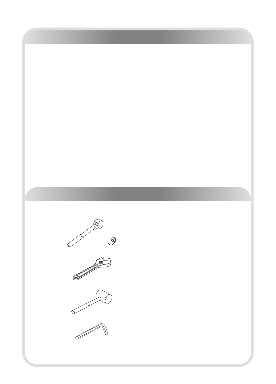
Tools Required
Ratchet Wrench and Socket
Adjustable Wrench
Rubber Mallet
Hex Key Wrench Set
─ 4 ─

─ 5 ─
Par ts List
NOTE: SOME OF THESE PARTS MAY COME PRE-INSTALLED
Item No. Description Qty Item No. Description Qty
1 Rear Frame 1 42 Weight Shroud B 1
2 Up Frame 1 43 Long Lat Bar 1
3 Rear Upright 1 44 Short Lat Bar 1
4 Right Base Frame 1 45 Adjustable Stopper 1
5 Right Top Frame For Guide Rod 1 46 Cable Retainer Bracket 2
6 Seat Pad Support Receptacle 1 47 Guide Rod Φ25*2.5*1855 4
7 Main Upright 1 48 BENCH Seat Pad 1
8 Left Base Frame 1 49 Back Pad 1
9 Left Top Frame For Guide Rod 1 50 Seat Pad 546*318*75 1
10 Press Arm Support 1 51 Back Pad 546*290*75 1
11 Press Station Base Frame 1 52 15LB Weight Plate 10
12 Chest Press Cam 1 53 10LB Weight Plate 18
13 Bench Main Frame 1 54 5LB Weight Plate 10
14 Bench Front Frame 1 55 Top Plate 2
15 Bench Rear Frame 1 56 Weight Pin 2
16 Bench Seat Pad Support 1 57 4.5" Pulley 19
17 Bench Back Pad Support 1 58 Foam Padding 10
18 Foam Adjustable Bracket 1 59 Pop Pin(Locking) 3
19 Front Upright 1 60 Ab Strap 1
20 Leg Extension Lever 1 61 Lat Strap 2
21 Pec Dec mount 1 62 Ankle Strap 1
22 Left Pec Dec Arm 1 63 Lat Bar Grip 4
23 Right Pec Dec Arm 1 64 Bench Seat Pad ADJ. Bar 1
24 Pec Dec Handle Bar 2 65 Ball Head for Pin 1
25 Foam Frame w/o Shaft 1 66 Spring Φ1.5*Φ13*43 1
26 Foam Frame w/Shaft 1 67 Spring Φ1*Φ13*38 1
27 Seat Pad Support 1 68 Pin Shaft 1
28 Back Pad ADJ. Bracket 1 69 Pin Knob 1
29 Left Leg Hold Leg Frame 1 70 Nylon Spacer 1
30 Right Leg Hold Leg Frame 1 71 Grip Φ26*Φ19*80 1
31 Pulley Bracket Block 1 72 Handle Grip Φ36*Φ30*188 3
32 Pulley Bracket 1 73 Safety Pin 2
33 Pulley Bracket w/Shaft 2 74 Pop Pin 1
34 Long Foam Tube 1 75 Pillow block Bearing 2
35 Press Arm 1 76 Pec Dec Stop Bumper 2
36 Right Squat Arm 1 77 Bearing Φ25 4
37 Left Squat Arm 1 78 Caster Black 2
38 Press Station Shaft 1 79 Foot Cap 1 □50.8 4
39 Bench Back Pad ADJ. Frame 1 80 Base Pad 8
40 Foam Shaft 1 81 □25 End Cap Bumper 1
41 Bottom Weight Shroud 2 82 U Shape Pin 1

─ 6 ─
Par ts List
NOTE: SOME OF THESE PARTS MAY COME PRE-INSTALLED
Item No. Description Qty Item No. Description Qty
83 Sping Φ1*Φ8*35 1 123 Long Pulley SpacerΦ20*Φ10.5*14 8
84 Nylon Lock Nut M6 17 124 Cable Adaptor 1
85 Slip Tension Pin 1 125 Flat Washer Φ13*Φ24*1.5 25
86 Shaft For Leg Extension Φ16*M8*61 1 126 Nylon Lock Nut M12 13
87 Gear Hook 7 127 Button Head Cap Screw M10*50 4
88 Short Chain Φ5*5 1 128 Button Head Cap Screw M10*25 12
89 Roller Pad Tube Cap Φ25 6 129 Flat Washer Φ11*Φ38*2 8
90 Plastic Washer Φ66*8 8 130 Button Head Cap Screw M12*85 4
91 Plug Φ50 2 131 Button Head Cap Screw M12*80 4
92 Plug □40*80 1 132 Button Head Cap Screw M12*125 4
93 Plug □50.8*76.2 4 133 Button Head Cap Screw M10*105 2
94 Plug □50.8 6 134 Button Head Cap Screw M10*85 6
95 Plug □44.5 4 135 Button Head Cap Screw M10*80 7
96 Plug □50*25 8 136 Button Head Cap Screw M10*75 12
97 Socket Set Screw M8*6 3 137 Button Head Cap Screw M10*70 11
98 Button Head Cap Screw M8*15 9 138 Button Head Cap Screw M10*65 7
99 Weight Stack Bumper 4 139 Button Head Cap Screw M10*60 1
100 Rubber Mat 1 140 Socket Set Screw 10-32*3.2 6
101 Chrome Washer Φ38*Φ11*2 2 141 Button Head Cap Screw M10*45 14
102 Big Washer Φ56.5*Φ10.5*5 2 142 Button Head Cap Screw M10*30 4
103 Flat Philips Screw M4*20 2 143 Flat Washer Φ11*Φ20*2 128
104 Bronze Bushing Φ25.4 8 144 Nylon Lock Nut M10 56
105 Bronze Bushing Φ12.2 6 145 Top Weight Shroud 2
106 Plastic Button 8 146 Hex Key S6 1
107 Aluminium Cap Φ32 3 147 Hex Key S4 1
108 Plug Φ25 2 148 Lube 1
109 Rubber Stopper 2 150 Selector Rod 2
110 Lat Cable 1 151 Screw Bolt M12*35 2
111 Low Row/Abdominal Cable 1 152 Hex Nut M10 1
112 Pec Dec Cable 1 153 □50.8 Foot Cap 2 4
113 Leg Press Cable 1 154 Button Head Cap Screw M8*25 8
114 Long Chest Cable 1 155 Flat Washer Φ9*Φ16*1.6 10
115 Short Chest Cable 1 157 Middle Weight Shroud 2
116 Long Chain Φ5*12 1 158 Small Spacer Φ17.5*Φ7*5 16
117 Flat Washer Φ9*Φ22*2 7 159 Button Head Cap Screw M6*18 16
118 Spring Washer Φ8 1 160 Flat Washer Φ6.6*Φ12*1.6 32
119 Spring Washer Φ10 17 161 Wrench 17-19 1
120 Bronze Bushing Φ16 2 162 Plug □40*80 1
121 Longer Pulley SpacerΦ20*Φ10.5*19.5 6 163 Hex Key 3/32" 1
122 Short Pulley SpacerΦ20*Φ10.5*11.5 2 164 Paint 1
─ 7 ─
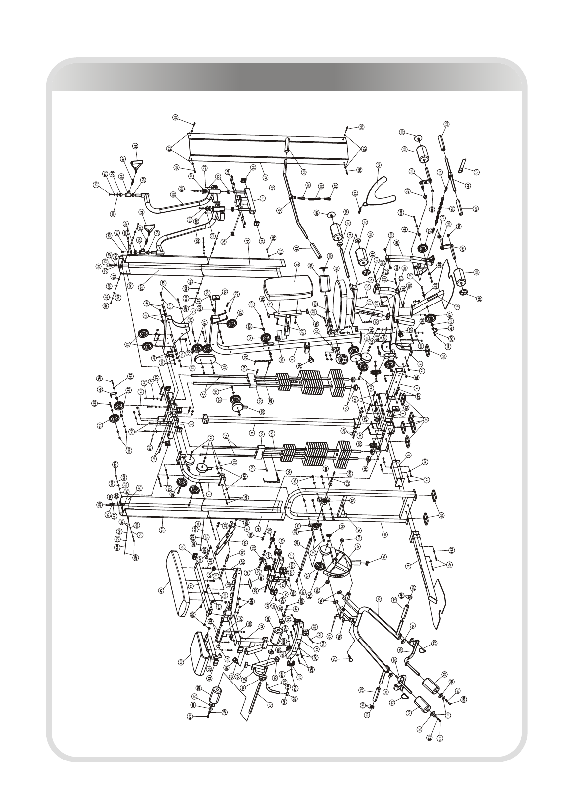
Exploded View

─ 8 ─
BHCS = Button Head Cap Screw
SHCS = Socket Head Cap Screw
FHCS = Flat Head Cap Screw
HHB = Hex Head Bolt
Measurement Guide

─ 9 ─
Assembly of the equipment takes professional installers about 2 hours. If this is
the first time you have assembled this type of equipment, plan to spend more
time. It is strongly recommended to assemble the equipment by professional
installers. You may find it quicker, safer, easier to assemble this equipment with
the help of a friend, as some of components may be large, heavy or awkward to
handle alone. It is important that you assemble your product in a clean, clear,
uncluttered area. This will enable you to move around the product while you are
fitting components and reduce the possibility of injury during assembly.
As with any assembled part, proper alignment and adjustment is critical. While
tightening the fasteners, be sure to leave room for adjustments. Do not fully
tighten the fasteners until instructed to do so. Be careful to assemble the
components in the sequence presented in this guide.
Assembly Instructions
─ 10 ─
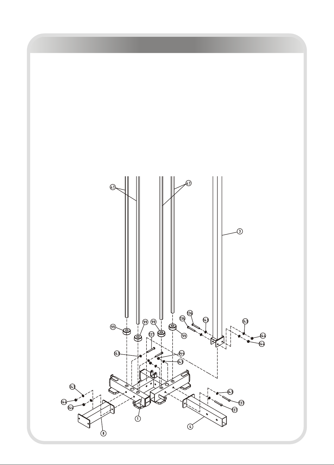
Assembly
Step 1
1. Attach the Right Base Frame (#4) to the Rear Frame (#1), using:
two M10*70 BHCS (#137) four Φ11*Φ20*2 Flat Washers (#143)
two M10 Nylon Lock Nuts (#144)
2. Attach the Left Base Frame (#8) to the Rear Frame (#1), using:
two M10*70 BHCS (#137) four Φ11*Φ20*2 Flat Washers (#143)
two M10 Nylon Lock Nuts (#144)
3. Attach four Guide Rod (#47) and four Weight Stack Bumper (#99) to the Rear
Frame (#1).
4. Attach the Rear Upright (#3) to the Rear Frame (#1), using:
two M10*75 BHCS (#136) four Φ11*Φ20*2 Flat Washers (#143)
two M10 Nylon Lock Nuts (#144)
Note: Hand tighten bolts and Nylon Lock nuts until machine is fully assembled.

─ 11 ─
Assembly
Step 2
1. Attach:
five 15LBS Weight Plates (#52) nine 10LBS Weight Plates (#53)
five 5LBS Weight Plates (#54) one Top Plate (#55)
to two Guide Rods (#47).
2. Attach one Weight Pin (#56) to one Top Plate (#55).
3. Repeat this step to complete another one.
4. Attach the Up Frame (#2) to four Guide Rods (#47) and the Rear Upright (#3),
using:
two M10*75 BHCS (#136) four Φ11*Φ20*2 Flat Washers (#143)
two M10 Nylon Lock Nuts (#144)
Note: Hand tighten bolts and Nylon Lock nuts until machine is fully assembled.

─ 12 ─
Assembly
Step 3
1. Attach the Front Upright (#19) to the Seat Pad Support Receptacle (#6), using:
two M10*75 BHCS (#136) four Φ11*Φ20*2 Flat Washers (#143)
two M10 Nylon Lock Nuts (#144)
2. Attach the Seat Pad Support Receptacle (#6) to the Right Base Frame (#4),
using:
two M10*75 BHCS (#136) four Φ11*Φ20*2 Flat Washers (#143)
two M10 Nylon Lock Nuts (#144)
Note: Hand tighten bolts and Nylon Lock nuts until machine is fully assembled.
─ 13 ─
Assembly
Step 4
1. Attach the Main Upright (#7) to the Seat Pad Support Receptacle (#6), using:
two M12*80 BHCS (#131) four Φ13*Φ24*1.5 Flat Washers (#125)
two M12 Nylon Lock Nuts (#126)
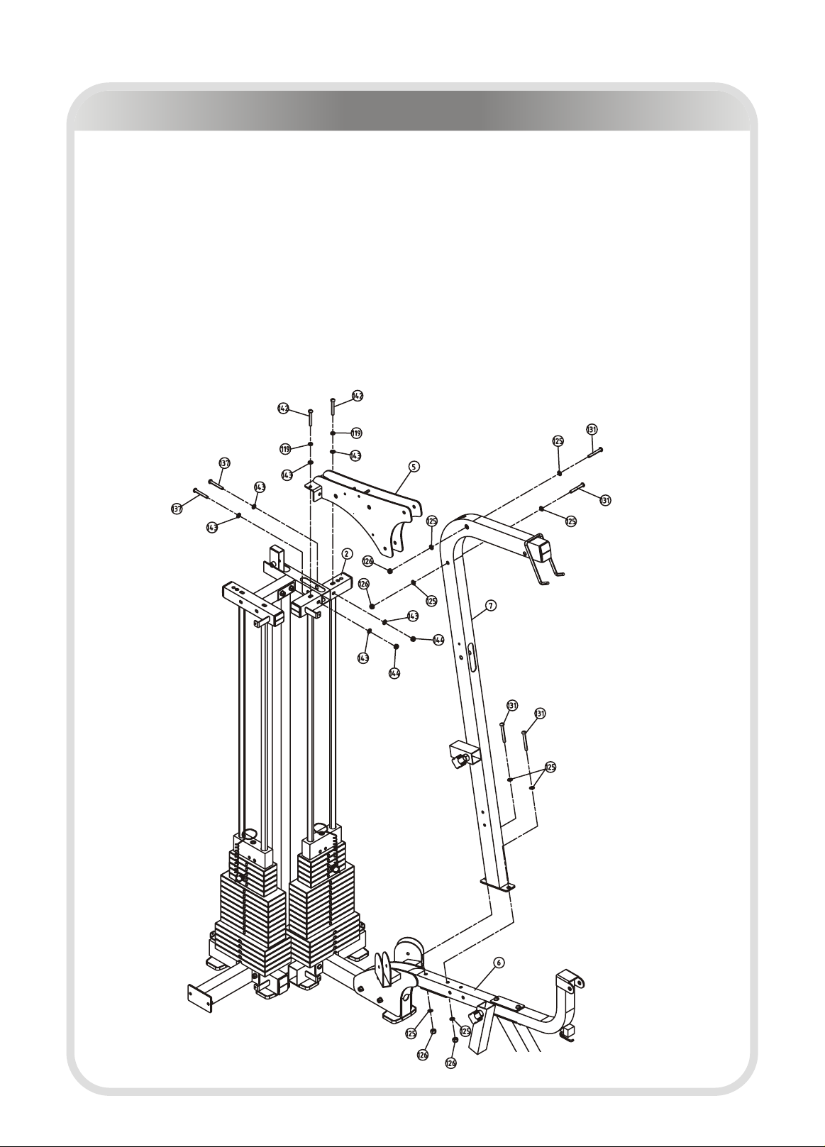
2. Attach the Right Top Frame For Guide Rod (#5) to the Up Frame (#2) and the
Main Upright (#7), using:
two M10*30 BHCS (#142) two M10*70 BHCS (#137)
two M12*80 BHCS (#131) four Φ13*Φ24*1.5 Flat Washers (#125)
six Φ11*Φ20*2 Flat Washers (#143) two M12 Nylon Lock Nuts (#126)
two M10 Nylon Lock Nuts (#144) two Φ10 Spring Washers (#119)
Note: Hand tighten bolts and Nylon Lock nuts until machine is fully assembled.

─ 14 ─
Assembly
Step 5
1. Attach the Press Station Base Frame (#11) to the Press Arm Support (#10),
and then to the Left Base Frame (#8), using:
two M10*85 BHCS (#134) four Φ11*Φ20*2 Flat Washers (#143)
two M10 Nylon Lock Nuts (#144)
2. Attach the Left Top Frame For Guide Rod (#9) to the Up Frame (#2) and the
Press Arm Support (#10), using:
two M10*30 BHCS (#142) two M10*70 BHCS (#137)
two M10*75 BHCS (#136) ten Φ11*Φ20*2 Flat Washers (#143)
four M10 Nylon Lock Nuts (#144) two Φ10 Spring Washers (#119)
Note: Hand tighten bolts and Nylon Lock nuts until machine is fully assembled.
─ 15 ─
Assembly
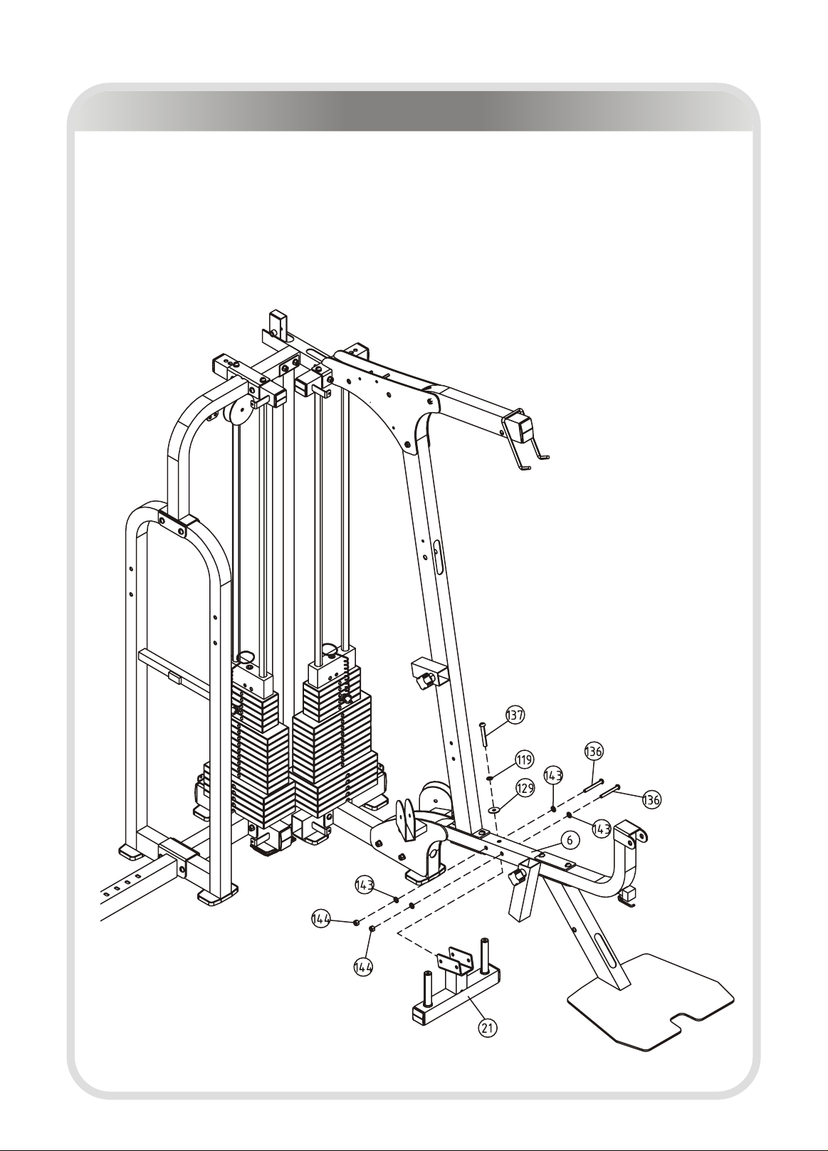
Step 6
Attach the Pec Dec mount (#21) to the Seat Pad Support Receptacle (#6), using:
two M10*75 BHCS (#136) one M10*70 BHCS (#137)
one Φ10 Spring Washer (#119) one Φ38*Φ11*2 Flat Washer (#129)
four Φ11*Φ20*2 Flat Washers (#143) two M10 Nylon Lock Nuts (#144)
Note: Hand tighten bolts and Nylon Lock nuts until machine is fully assembled.
─ 16 ─
Assembly
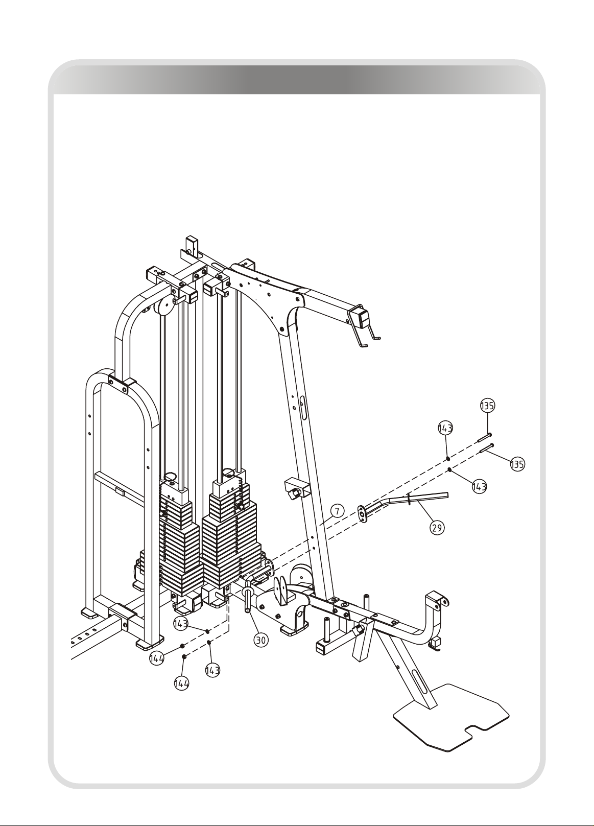
Step 7
Attach the Left Leg Hold Leg Frame (#29) and the Right Leg Hold Leg Frame
(#30) to the Main Upright (#7), using:
two M10*80 BHCS (#135) four Φ11*Φ20*2 Flat Washers (#143)
two M10 Nylon Lock Nuts (#144)
Note: Hand tighten bolts and Nylon Lock nuts until machine is fully assembled.
─ 17 ─
Assembly
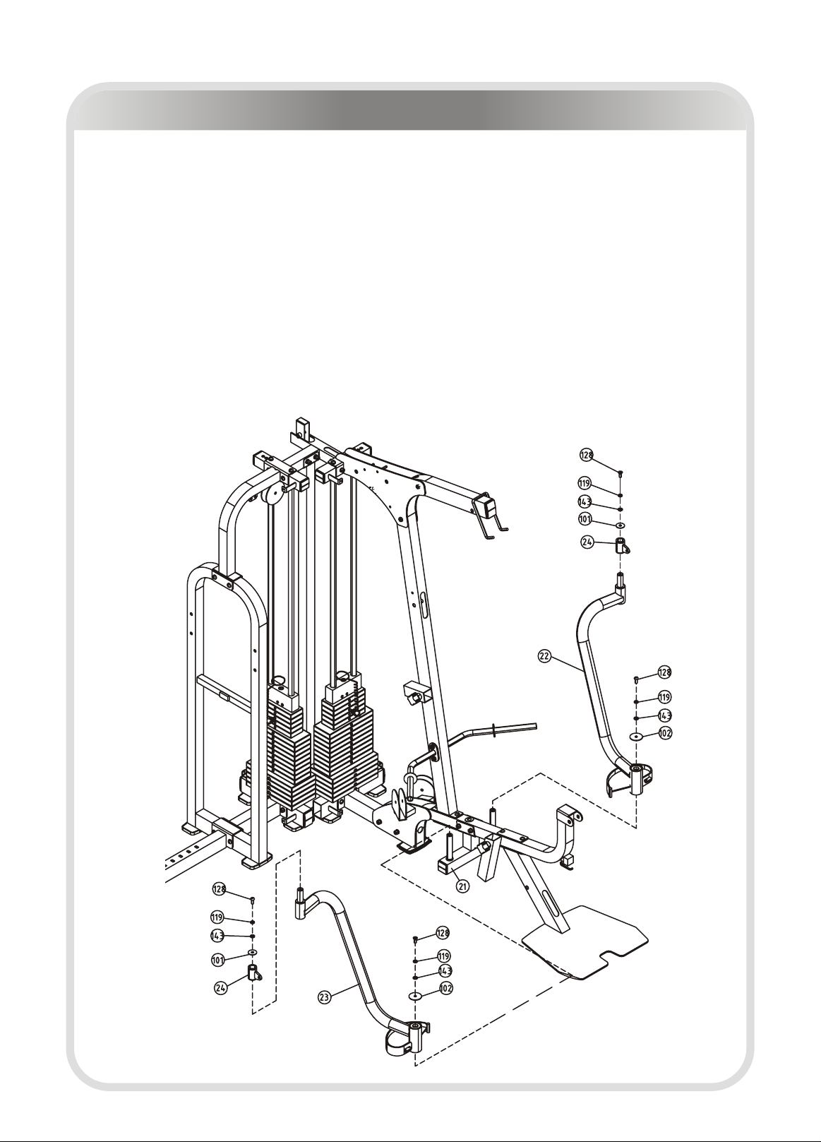
Step 8
1. Attach the Left Pec Dec Arm (#22) to the Pec Dec mount (#21), using:
one M10*25 BHCS (#128) one Φ10 Spring Washer (#119)
one Φ11*Φ20*2 Flat Washer (#143) one Φ56.5*Φ10.5*5 Big Washer (#102)
2. Attach the Pec Dec Handle Bar (#24) to the Left Pec Dec Arm (#22), using:
one M10*25 BHCS (#128) one Φ10 Spring Washer (#119)
one Φ11*Φ20*2 Flat Washer (#143) one Φ38*Φ11*2 Chrome Washer (#101)
3. Repeat this step to Attach the Right Pec Dec Arm (#23) to the Pec Dec mount
(#21), and Attach the Pec Dec Handle Bar (#24) to the Right Pec Dec Arm (#23).
Note: Hand tighten bolts and Nylon Lock nuts until machine is fully assembled.
─ 18 ─
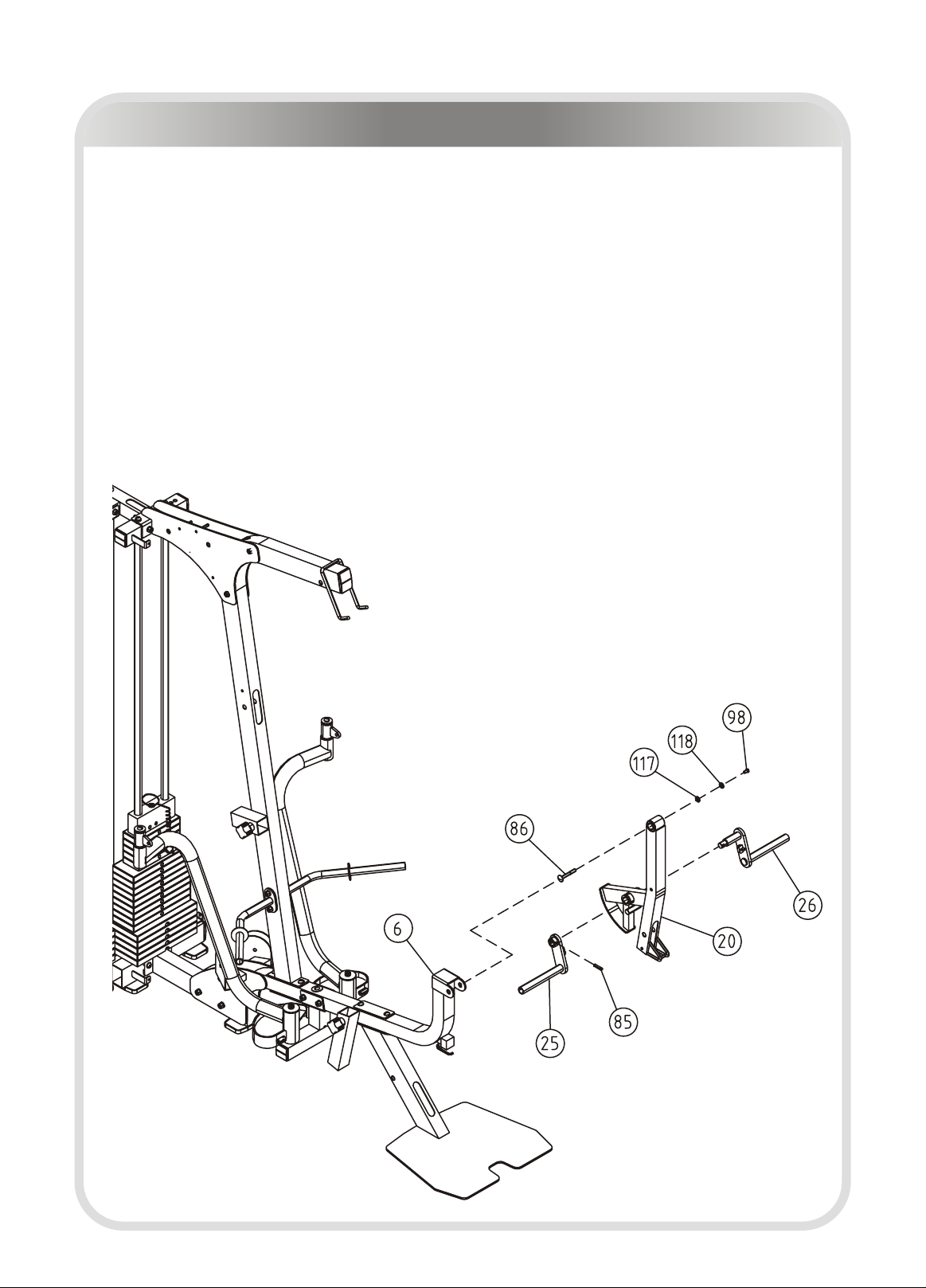
Assembly
Step 9
1. Attach the Leg Extension Lever (#20) to the Seat Pad Support Receptacle
(#6), using:
one Φ16*M8*61 Shaft For Leg Extension (#86) one Φ9*Φ22*2 Flat Washer (#117)
one Φ8 Spring Washer (#118) one M8*15 BHCS (#98)
2. Attach the Foam Frame w/Shaft (#26) to the Foam Frame w/o Shaft (#25) by
the Leg Extension Lever (#20), using:
one Φ8*32 Slip Tension Pin (#85)
Note: Hand tighten bolts and Nylon Lock nuts until machine is fully assembled.
─ 19 ─
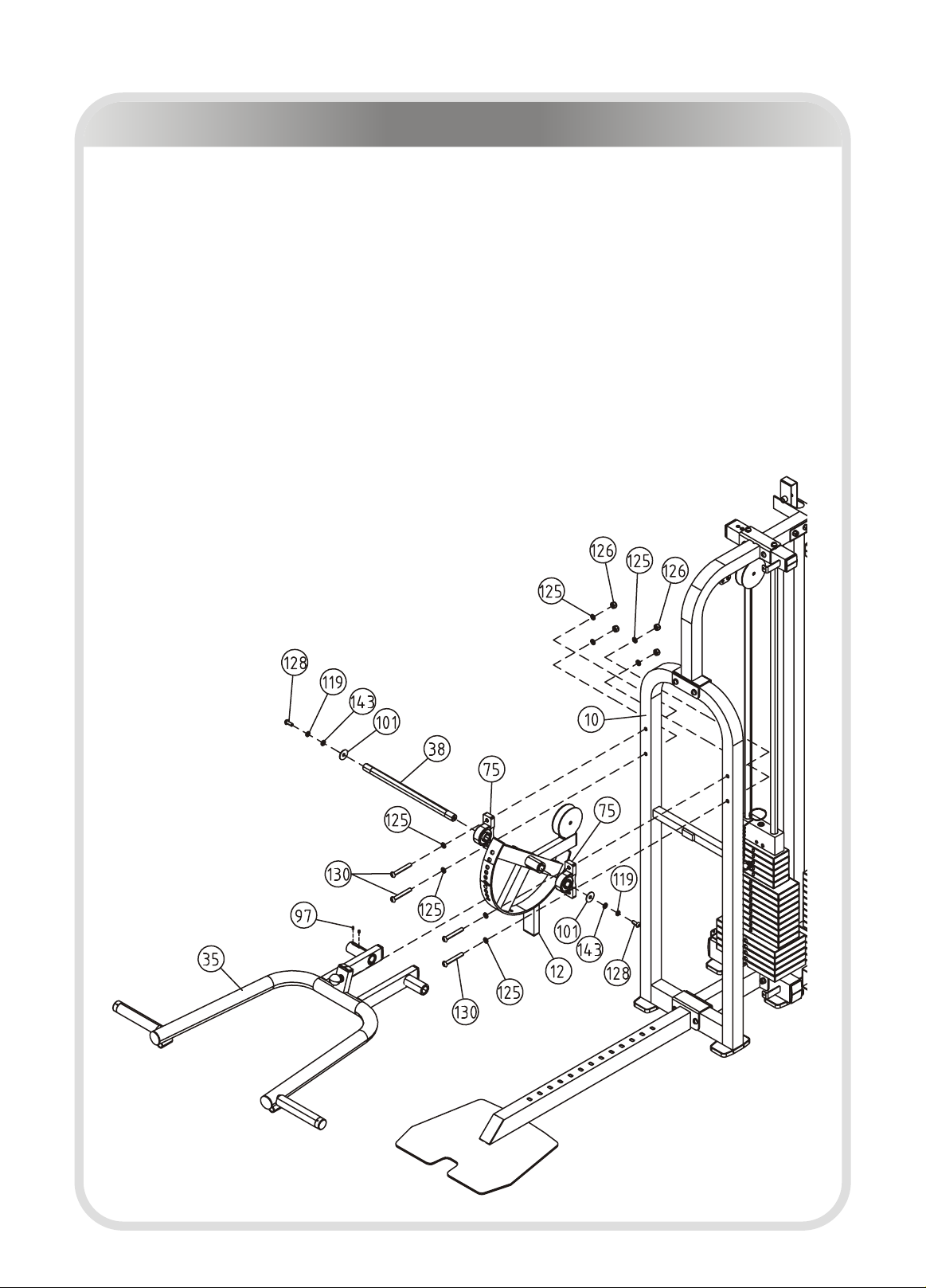
Assembly
Step 10
1. Attach the Press Arm (#35) to the Chest Press Cam (#12), using:
one Φ25.2*Φ25*437 Press Station Shaft (#38) two Pillow Block Bearings (#75)
two Φ38*Φ11*2 Chrome Washers (#101) two Φ11*Φ20*2 Flat Washers (#143)
two Φ10 Spring Washers (#119) two M10*25 BHCS (#128)
two M8*6 Socket Set Screws (#97)
2. Attach the Press Arm (#35) and the Chest Press Cam (#12) to the Press Arm
Support (#10), using:
four M12*85 BHCS (#130) eight Φ13*Φ24*1.5 Flat Washers (#125)
four M12 Nylon Lock Nuts (#126)
Note: Hand tighten bolts and Nylon Lock nuts until machine is fully assembled.

─ 20 ─
Assembly
Step 11
1. Attach the Bench Rear Frame (#15) to the Bench Main Frame (#13), using:
two M10*105 BHCS (#133) four Φ11*Φ20*2 Flat Washers (#143)
two M10 Nylon Lock Nuts (#144)
2. Attach the Bench Front Frame (#14) to the Bench Main Frame (#13), using:
two M10*75 BHCS (#136) four Φ11*Φ20*2 Flat Washers (#143)
two M10 Nylon Lock Nuts (#144)
Note: Hand tighten bolts and Nylon Lock nuts until machine is fully assembled.
Other TKO Home Gym manuals


Popular Home Gym manuals by other brands

Keys Fitness
Keys Fitness Power System KF-2060 owner's manual

Weider
Weider Black 150 Xwb Bench Manuel de l'utilisateur

Weider
Weider Pro 2000 Gebruikershandleiding

Hoist Fitness
Hoist Fitness HD2300 owner's manual

Inspire
Inspire M1 Assembly & operation manual

CYBEX
CYBEX 13100-999-4 C Owner's and service manual


 manual")


