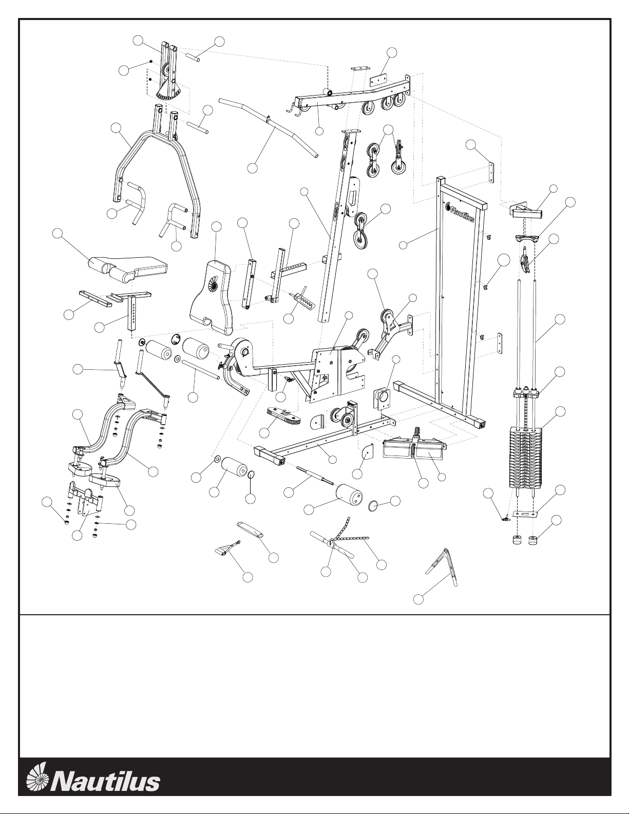
Nautilus NS-600 User manual

TM
NS-600
Assembly Instructions
Rev. B

TM
NS-600
2
Gym Components Gym Components
Part # Part #
1 Main Base 1 14786
2 Rear Frame 1 14785
3 Top Frame 1 14124
4 Front Upright 1 14787
5 Leg Extension Frame 1 14434
6 Pulley Mount 1 14788
7 Calf Raise / Low Pulley Frame 1 14127
8 Top Stack Support Frame 1 14125
9 Cable Housing 1 14137
10 2 inch Backing Plate 3 14105
11 3 inch Backing Plate 1 14007
12 Press Arm Support Assembly 1 14132
13 Press Arm 1 14131
14 Right Press Arm Handle 1 14133
15 Left Press Arm Handle 1 14134
16 Pec Fly Mount 1 14135
17 Pec Fly Cam 2 14473
18 Right Pec Fly Arm 1 14148
19 Left Pec Fly Arm 1 14149
20 Pec Fly Handle 2 14151
21 Pec Fly Pulley Bracket 1 14438
22 Seat Adjuster 1 14128
23 Seat Cross Tube 1 14101
24 Back Pad Tube 1 14465
25 Back Pad Adjuster 1 14456
26 Back Pad Adjustment Plate 1 14469
27 Seat Pad 1 14190
28 Back Pad 1 14189
29 Pulley Bracket 1 14136
30 Pec Double Floating Pulley Bracket 1 14138
31 Double Floating Pulley Bracket 2 14138
32 Guide Rod Holder 1 14174
33 Low Pulley Cover 2 14437
34 T Handle Pop Pin 1 14211
35 Locking Roller Pad 2 14493
36 Foam Roller Pad 8"L 2 14270
37 Locking Roller End Cap 2 14486
38 Roller End Cap 2 14165
39 Plastic Washer 2 92058
40 Locking Roller Bar 1 14460
41 Roller Bar 1 14100
42 Plastic Cap 4 14158
43 3 1/2" Pulley 2 14173
44 4 1/2" Pulley 9 14537
45 Press Arm Support Shaft 1 14111
46 Press Arm Pivot Shaft 1 14110
47 Snap Cap Large 2 14182
48 Top Weight Assembly 1 14679
49 Weight Plate 19 14342
50 Weight Stack Bottom Plate 1 14106
51 Weight Stack Cushion 2 14176
52 Guide Rod 2 14102
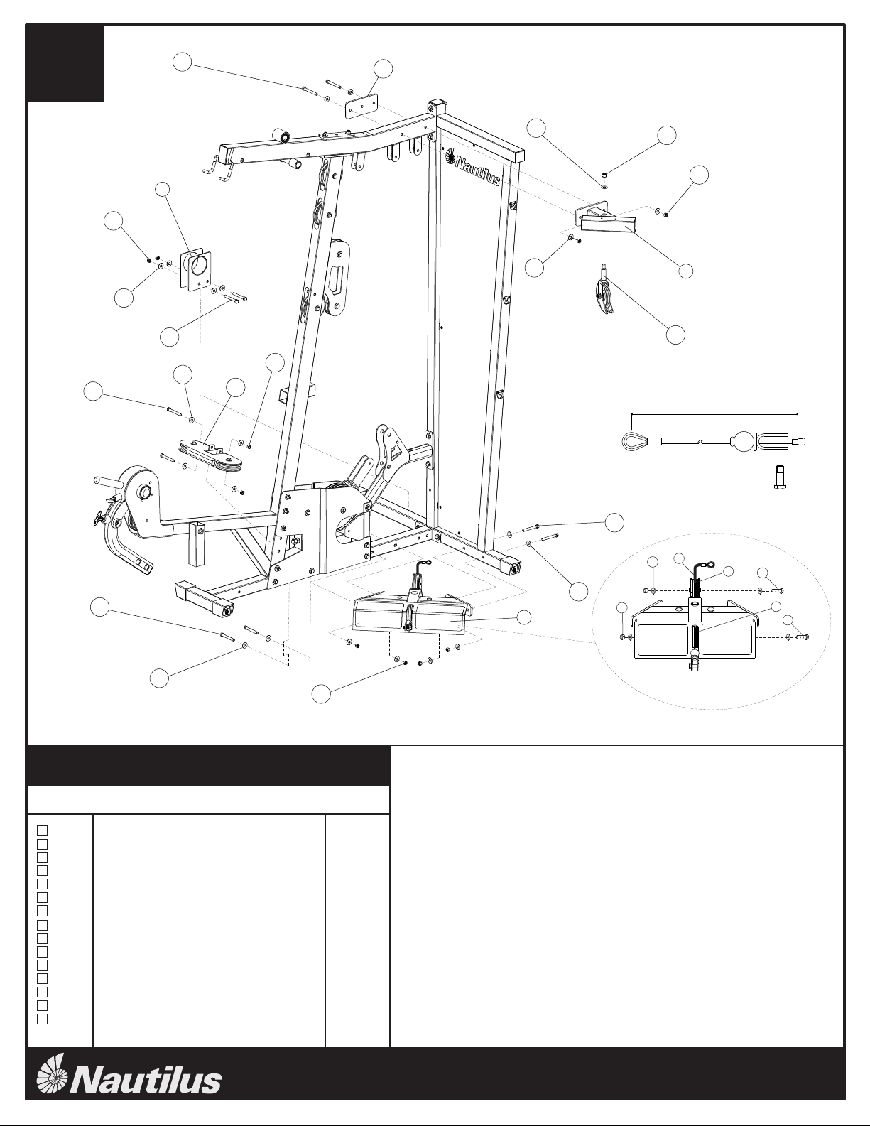
CABLE
53 Cable #1 - Pulldown Cable (226") 1 14791
54 Cable #2 - Mid Pulley Cable (96.75") 1 14792
55 Cable #3 - Low Row Cable (137.75") 1 14793
56 Cable #4 - Pec Fly Cable (122.5") 1 14794
HARDWARE
57 Hex Bolt - 1/2" x 3 1/4"L 1 14243
58 Hex Bolt - 3/8" x 4 1/2"L 1 92170
59 Hex Bolt - 3/8" x 4 1/4"L 4 14246
60 Hex Bolt - 3/8" x 4"L 1 14247
61 Hex Bolt - 3/8" x 3 1/4"L 8 14267
62 Hex Bolt - 3/8" x 3"L 16 14245
63 Hex Bolt - 3/8" x 2 3/4"L 4 14241
64 Hex Bolt 3/8" x 2 1/4"L 3 14265
65 Hex Bolt 3/8" x 2"L 5 14242
66 Hex Bolt - 3/8" x 1 3/4"L 3 14239
67 Hex Bolt - 3/8" x 1 1/2"L Threadlock 2 14249
68 Cap Head Screw 1/4 x 1"L Threadlock 2 14258
69 Cap Head Screw 1/4" x 1/2"L Threadlock 2 14259
70 Button Head Screw 1 3/4"L 2 14256
71 Button Head Screw 1"L Threadlock 4 14251
72 1 3/8" x 1/2" Flat Washer 4 14272
73 1" x 1/2" Flat Washer 4 14273
74 3/8" Flat Washer 87 14233
75 Shim Washer 4 14274
76 1/2" Lock Nut 7 14232
77 3/8" Lock Nut 42 14234
78 Pulley Spacer 1"L 1 14196
79 Step Spacer 5/8"H 4 14195
80 Step Spacer 1"H 2 14795
81 Step Spacer 21/32"H 2 14796
82 Set Screw 5/16" x 1/4"L 6 14277
ACCESSORIES AND TOOLS
83 Rower Bar 1 14113
84 AB Strap 1 14215
85 Felt Back Ankle Strap 1 14217
86 Dual Ring Handle Strap 1 14384
87 Chain 1 92053
88 Lat Bar 1 14142
89 Cable Clip 4 92054
90 Weight Selector Pin 1 14210
91 M4 Allen Wrench 1 14680
92 M5 Allen Wrench 1 14532
93 M6 Allen Wrench 1 14533
94 M8 Allen Wrench 1 14534
95 Touch Up Paint White 1 14536
96 Touch Up Paint Gray 1 14535
97 NS 600 Documentation 1 14797
98 Decal Kit 1 14789

51
50
49
48
47
46
45
75
42
41
40
39
38 37
36
35
34
33
32
31
30
29
28
27
26
25
24
23
22
21
20
19
18
17
16
15
14
13
12
11
10
9
8
7
6
5
4
3
2
1
44b
TM
NS-600
3
A.
B.
Compare the Bill of Materials to the box contents to insure that all parts are
present before installation begins.
Unpackage parts and place them near the final assembled location to avoid
moving the gym when fully assembled.
83
87
84
86
85
90
43
44
88
89
52

1” 2” 3” 4” 5”
TM
NS-600
4
Hex Bolt
Button Head
Cap Head
Shim Washer
Lock Nut
Flat Washer
Step Spacer
Cable Clip
RequiredTools:
9/16” or 14mm Wrench or Socket (Two Required)
3/4” Wrench or Socket
Adjustable Wrench
4, 5, 6 and 8mm Allen Wrenches (Included w/ Gym)
Flat Head
Self Drilling

Before assembling this gym, please be aware that this piece of equipment can be assembled in two different configurations.
The Weight Stack can be assembled on either side of the gym depending on what best fits your living space.This is accomplished simply by
assembling the Rear Frame (2), Top Stack Support Frame (8), and Calf Raise / Low Pulley Frame (7) on the opposite side of the machine.
This gym is supplied with an instructional work out diagram which is to be adhered to the Rear Frame (2) back panel. See note in diagram above
for recommended location.
The following assembly instructions show the gym assembled with the weight stack on the left side. To assemble the gym with the weight stack on
the right side, simply assemble the Rear Frame (2), Top Stack Support Frame (8), and Calf Raise / Low Pulley Frame (7) on the opposite side of
the machine as shown in the instructions.
Be sure to place the NS 600 gym as close to its final location before adding weight plates. The gym is designed so that the rear of the frame can
sit directly against a wall. Please allow a minimum of 24” on each side of the gym from the nearest wall or obstruction. The weight stack side of
the gym will need a minimum of 48” from any obstruction. If an attachment such as a leg press is used now or in the future, please allow for 48” on
the side opposite the weight stack.
TM
NS-600
5
Recommended location for instructional
work out diagram.
2
7
8
7
2
8

10
6
5
4
3
2
1
77
74
62 3"L
62 3"L
62 3"L
59 4 1/4"L
58 4 1/2"L
61 3 1/4"L
59 4 1/4"L
61 3 1/4"L
10
10
74
77
Main Base
Rear Frame
Top Frame
Front Upright
Leg Extension Assembly
Pulley Mount
2 Inch Backing Plate
Hex Bolt 3/8" x 4 1/2"L
Hex Bolt 3/8" x 4 1/4"L
Hex Bolt 3/8" x 3 1/4"L
Hex Bolt 3/8" x 3"L
3/8" Flat Washer
3/8" Lock Nut
A. Attach Main Base (1) to Rear Frame (2) using hardware shown. Do not
tighten hardware.
B. Attach Leg Extension Assembly (5) to Main Base (1) using hardware shown.
Do not tighten hardware.
C. Attach Front Upright (4) to Leg Extension Assembly (5) using hardware shown.
Do not tighten hardware.
D. Attach Top Frame (3) to Front Upright (4) and Rear Frame (2) using hardware
shown and 2 Inch Backing Plate (10). Do not tighten hardware.
E. Attach Pulley Mount (6) to Leg Extension Assembly (5) and Rear Frame (2)
using hardware shown and 2 Inch Backing Plate (10). Tighten all hardware
used in this step securely.
TM
NS-600
6
Step #1 Materials:
step
1
#Description Qty.
1
1
1
1
1
1
3
1
4
4
6
30
15
1
2
3
4
5
6
10
58
59
61
62
74
77

Calf Raise / Low Pulley Frame
Top Stack Support Frame
Cable Housing
3 Inch Backing Plate
Pec Fly Pulley Bracket
Pulley Bracket
3 1/2" Pulley
Low Row Cable
Hex Bolt 3/8" x 3 1/4"L
Hex Bolt 3/8" x 3"L
Hex Bolt 3/8" x 2"L
1/2" Flat Washer Narrow
3/8" Flat Washer
1/2" Lock Nut
3/8" Lock Nut
A. Attach Top Stack Support Frame (8) to Top Frame using a 3 Inch Backing Plate
(11) and the hardware shown. Tighten hardware firmly.
B. Attach Pulley Bracket (29) to Top Stack Support Frame (8) using hardware
shown. Do not tighten hardware.
C. Attach Cable Housing (9) to Main Base using hardware shown.Tighten hardware
firmly. NOTE: If an exercise attachment such as the NS-75 is used, do not install
Cable Housing (9).
D. Attach Pec Fly Pulley Bracket (21) to Leg Extension Assembly using hardware
shown. Tighten hardware firmly.
E. Install Low Row Cable (55) through Calf Raise / Low Pulley Frame (7). See
Detail A. Feed the looped end of the cable through the foot plate side of the Calf
Raise / Low Pulley Frame (7). Attach two 3 1/2" Pulleys (43) using hardware
shown, making sure that the cable runs in the groove on the low side of the pulley.
Final installation of the cable will be completed on Step 9. NOTE: Make sure
that the cable is NOT wrapped around the cable stop.
TM
NS-600
7
Step #2 Materials:
step
2
#Description Qty.
1
1
1
1
1
1
2
1
2
8
2
1
24
1
12
7
8
9
11
21
29
43
55
61
62
65
73
74
76
77
21
7
9
29
8
11
62 3"L
62
3"L
74
77
73 76
74
77
61
3 1/4"L
62
3"L
77
74
74
62
3"L
77
74
77
55
43
43
65
65
2”L
2”L
A
74
F. Attach Calf Raise / Low Pulley (7) to the Main Base and Rear Frame using
hardware shown. Tighten hardware firmly.
137.75" (3500mm)

75
42
61
16
20
19
18
Top View
Path
Pec Fly Mount
Pec Fly Cam
Right Pec Fly Arm
Left Pec Fly Arm
Pec Fly Handle
Plastic Cap
Hex Bolt 3/8" x 3 1/4"L
Cap Head Allen Bolt 1/4" x 1/2"L Threadlock
1 3/8" x 1/2" Flat Washer
3/8" Flat Washer
Shim Washer
1/2" Lock Nut
3/8" Lock Nut
A. Attach Pec Fly Mount (16) to Main Base using hardware shown. Tighten hardware
firmly.
B. Slide Pec Fly Cam (17) onto Left Pec Fly Arm (19) paying close attention to the
orientation shown above. Attach the Left Pec Fly Arm (19) to the Pec Fly Mount
(16) using the hardware shown. Tighten hardware securely making sure that the
Pec Fly Arm can rotate freely.
C. Repeat step B using the Right Pec Fly Arm (18).
D. Install Pec Fly Handle (20) in the Left Pec Fly Arm (19) using the hardware shown.
Tighten hardware securely making sure that the Pec Fly Handle (20) can rotate
freely. Install Allen Bolt (69) to Pec Fly Handle (20) as shown. Tighten firmly.
NOTE: Make sure that the path of the Pec Fly Handle is similar to the path shown
in the Top View.
E. Repeat step D using the Right Pec Fly Arm (18).
TM
NS-600
8
Step #3 Materials:
step
3
#Description Qty.
1
2
1
1
2
4
2
2
4
4
4
4
2
16
17
18
19
20
42
61
69
72
74
75
76
77
69 1/2"L
72
76
3 1/4"L
77
74
17
F. Install Plastic Cap (42) in the four locations shown. The Plastic Cap (42) should
snap into place locking around the Shim Washer (75). NOTE: Rubber Mallet
may be needed to install Plastic Cap.

39
38
37
36
35
15
14
47 45
12
46
13
40
41
82 1/4"L
82 1/4"L
71 1"L
Press Arm Support Assembly
Press Arm
Right Press Arm Handle
Left Press Arm Handle
Locking Roller Pad
Foam Roller Pad 8"L
Locking Roller End Cap
Roller End Cap
Plastic Washer
Locking Roller Bar
Roller Bar
Press Arm Support Shaft
Press Arm Pivot Shaft
Snap Cap Large
Button Head Screw 1"L Threadlock
3/8" Flat Washer
Set Screw 5/16" x 1/4"L
A. Attach Press Arm Support Assembly (12) to the Top Frame using the Press Arm
Support Shaft (45). Align shaft and tighten with 4 set screws (82) as shown.
B. Attach Press Arm (13) to Press Arm Support Assembly (12) using the Press Arm
Pivot Shaft (46). Pull Back on Press Arm Pop Pin or remove for ease of assembly.
Align Shaft and tighten two set screws (82) as shown.
C. Attach Press Arm Handles (14) (15) using the hardware shown. Tighten hardware
firmly.
D. Slide the Roller Bar (41) through the Leg Extension tube. Either of the bottom two
holes can be used depending on best fit for user.
E. Slide a Plastic Washer (39) followed by a Foam Roller Pad (36) on the Roller Bar
(41). Press the Roller End Cap (38) firmly into the Roller Bar (41). Repeat for the
opposite side.
TM
NS-600
9
Step #4 Materials:
step
4
#Description Qty.
1
1
1
1
2
2
2
2
2
1
1
1
1
2
4
4
6
12
13
14
15
35
36
37
38
39
40
41
45
46
47
71
74
82
F. Slide the Locking Roller Bar (40) through the leg extension tube as shown making
sure that it is centered. Slide the Locking Roller Pad (35) on the Locking Roller
Bar (40). Press the Locking Roller End Cap (37) into the Locking Roller Bar (40).
Repeat for the opposite side making sure that the Locking Rollers are aligned.
PRESS ARM
POP PIN
74

34
26
24
25
23 22
27
28
66 1 3/4"L
62 3"L
77
74
64 2 1/4"L
74
76
57
73 3 1/4"L
Seat Adjuster
Seat Cross Tube
Back Pad Tube
Back Pad Adjuster
Back Pad Adjustment Plate
Seat Pad
Back Pad
T Handle Pop Pin
Hex Bolt 1/2" x 3 1/4"L
Hex Bolt 3/8" x 3"L
Hex Bolt 3/8" x 2 1/4"L
Hex Bolt 3/8" x 1 3/4"L
1/2" Flat Washer Narrow
3/8" Flat Washer
1/2" Lock Nut
3/8" Lock Nut
A. Attach Seat Cross Tube (23) to Seat Adjuster (22) using hardware shown.
Tighten hardware securely.
B. Attach Seat Pad (27) to Seat Cross Tube (23) and Seat Adjuster (22) using
hardware shown. Tighten hardware secruely.
C. Attach T Handle Pop Pin (34) to the Leg Extension Assembly with adjustable
wrench.
D. Install Seat Adjuster (22) in Leg Extension Assembly in the slot shown. Use the
Pop Pin (34) to adjust height. NOTE: Pop Pin is threaded so that the seat can
be locked in place.
E. Attach Back Pad Tube (24) to Back Pad (28) using hardware shown. Tighten
hardware securely.
TM
NS-600
10
Step #5 Materials:
step
5
#Description Qty.
1
1
1
1
1
1
1
1
1
2
2
3
3
9
2
2
22
23
24
25
26
27
28
34
57
62
64
66
73
74
76
77
F. Attach Back Pad Tube (24) to Back Pad Adjuster (25) using hardware shown.
Tighten hardware securely making sure the Back Pad Tube (24) can rotate freely.
G. Attach Back Pad Adjustment Plate (26) to Back Pad Tube (24) using hardware
shown. Make sure that the Back Pad Adjustment Pin rests inside the slot of the
Back Pad Adjustment Plate (26). Tighten hardware securely making sure the Back
Pad Adjustment Plate (26) can rotate freely.
H. Install Back Pad Adjuster (25) in Front Upright in the slot shown.
BACK PAD
ADJUSTMENT PIN

51
50
49
52
48
32
90
68 1"L
Guide Rod Holder
Top Weight Assembly
Weight Plate
Weight Stack Bottom Plate
Weight Stack Cushion
Guide Rod
Cap Head Allen Bolt 1/4" x 1"L Threadlock
Weight Selector Pin
A. Slide Weight Stack Cushion (51) on each Guide Rod (52) allowing approximately
3 inches of Guide Rod showing below the Weight Stack Cushion (51). Insert
Guide Rods (52) into holes in the Calf Raise/Low Pulley Frame as shown.
B. Slide Weight Stack Bottom Plate (50) on top of Weight Stack Cushions (51).
C. Place Nineteen Weight Plates (49) and the Top Weight Assembly (48) on the
Guide Rods (52) as shown. Install Weight Plates (49) so that the selector pin hole
faces forward and is located on the bottom of the plate. Install the Top Weight
Assembly (48) so that the head of the bolt is facing forward. This gym is supplied
with individual weight plate numbering decals that should be applied to the gym
after the weight stack is assembled.
D. Slide Guide Rod Holder (32) on the top of the Guide Rods (52) and attach the
Guide Rod Holder (32) to the Top Stack Support Frame using the hardware shown.
Tighten hardware securely.
E. Place Weight Selector Pin (90) in the bottm Weight Plate (49).
TM
NS-600
11
Step #6 Materials:
step
6
#Description Qty.
1
1
19
1
2
2
2
1
32
48
49
50
51
52
68
90

31
63
79
77
65
74
2 3/4"L
2"L
Double Floating Pulley Bracket
4 1/2" Pulley
Cable #1 - Pull Down
Hex Bolt 3/8" x 2 3/4"L
Hex Bolt 3/8" x 2"L
3/8" Flat Washer
3/8" Lock Nut
Step Spacer 5/8"H
B. Thread one end of Cable #1 (53) into the Top Weight Assembly as shown in detail A. Do not
tighten locking nut.
C. Remove the Ball, Washer, and U-Bracket from the other end of Cable #1.
D. Route Cable #1 (53) over the Pulley located above the weight stack and around a Pulley
installed in a Double Floating Pulley Bracket (31) as shown.
E. Route Cable #1 (53) over two 4 1/2" Pulleys (44) located on the Top Frame and around a
Pulley installed on a second Double Floating Pulley Bracket (31) as shown. Proceed by
routing the Cable around a 4 1/2" Pulley on the Top Frame.
A. Attach Three 4 1/2" Pulleys (44) to the brackets located on the Top Frame using the hardware
shown in detail B. Tighten hardware securely.
TM
NS-600
12
Step #7 Materials:
step
7
#Description Qty.
2
5
1
2
3
6
5
4
31
44
52
63
65
74
77
79
F. Route Cable #1 around the 4 1/2" Pulley installed in the bracket on the Front Upright and over
the Pulley located just above the bracket. Proceed by routing the cable around the lower
Pulley on the Press Arm Support, around the upper Pulley on the Front Upright, and around
the upper Pulley on the Press Arm Support as shown.
G. Feed Cable #1 (53) Through the Top Frame tube and out the front slot. Re-install the Ball,
Washer, and U-Bracket to the end of the cable. Make Sure the rubber o-ring is still in its
original position.
53
H. Loop Cable #1 around a 4 1/2" Pulley (44) and attach it to the Top Frame in Location A using
hardware shown. Proceed by looping the Cable around a 4 1/2" Pulley (44) and attach it to
the Top Frame in Location B using the hardware shown. Make sure the cable is seated properly
in the Pulleys, and tighten hardware securely.
44
A
B
B
A
C
230" (5840mm)

77
80 81
74
63
54
44
30
64 2 1/4"L
2 3/4"L
Pec Fly Double Floating Pulley Bracket
4 1/2" Pulley
Cable #2 - Mid-Pulley Cable
Hex Bolt 3/8" x 2 3/4"L
Hex Bolt 3/8" x 2 1/4"L
3/8" Flat Washer
3/8" Lock Nut
Step Spacer 1"H
Step Spacer 21/32"H
C. Attach looped end of Cable #2 (54) to the Pulley Mount bracket using the hardware
shown in detail A.
D. Route Cable #2 (54) around the 4 1/2" Pulley located on the Leg Extension
assembly and around the 4 1/2" Pulley on the Pulley Mount Bracket. Proceed by
routing the Cable around the lower Pulley on the Double Floating Pulley Bracket
(30) as shown.
E. Route Cable #2 (54) around the 4 1/2" Pulley on the Pec Fly Double Floating Pulley
Bracket (30). Continue by routing Cable over the 3 1/2" Pulley in the bracket on the
Front Upright and over the 4 1/2" Pulley adjacent to it.
TM
NS-600
13
Step #8 Materials:
step
8
#Description Qty.
1
2
1
2
1
2
3
2
2
30
44
54
63
64
74
77
80
81
F. Re-install the Ball, Washer, and U-Bracket to the end of the cable. Be sure that the
rubber o-ring is in its original position.
B. Remove the Ball, Washer, and U-Bracket from one end of Cable #2 (54).
A. Attach Two 4 1/2" Pulleys (44) to the brackets shown in detail A using the hardware
shown. Tighten hardware securely.
A
BC
91.5" (2325mm)

77
74
78
74 60
55
4"L
Cable #1 - Low Row
Hex Bolt 3/8" x 4"L
3/8" Flat Washer
3/8" Lock Nut
Pulley Spacer 1"L
A. Remove the lower Pulley from the Double Floating Pulley Bracket (31). Loop
Cable #3 (55) around the Pulley and re-install the Pulley as shown. Tighten
hardware firmly.
B. Wrap Cable #3 (55) under the Cable Housing (9) and attach the termination to
the Rear Frame using the hardware shown in detail A. DO NOT OVERTIGHTEN.
NOTE: Make sure to route Cable through the hole in the Pulley Mount tube.
NOTE:
This Cable termination is used for exercise attachments such as the NS-75. If
an attachment is used, do not install Cable Housing (9).
Please refer to attachment instructions for installation.
TM
NS-600
14
Step #9 Materials:
step
9
#Description Qty.
1
1
2
1
1
55
60
74
77
78
31
9A
C
B

70
70
74
74
74
74
77
77
74
74
67
67
33
33
44
56
30
Low Pulley Cover
4 1/2" Pulley
Cable #4 - Pec Fly Cable
Hex Bolt 3/8" x 1 1/2"L Threadlock
Button Head Screw 1 3/4"L
3/8" Flat Washer
3/8" Lock Nut
A. Attach two 4 1/2" Pulleys (44) to either side of the Leg Extension Assembly using
the Low Pulley Cover (33) and the hardware shown. Note the orientation of the
Low Pulley Covers. Tighten hardware firmly.
B. Attach the Cable #4 (56) termination to the left Pec Fly Cam using the hardware
shown. Be sure to place the groove in the termination bracket against the cam.
Tighten hardware securely.
C. Remove the bracket and spacer from the other end of Cable #4 (56). Route the
Cable around the left Pulley in the Pec Fly Pulley Bracket (21) as shown. Proceed by
routing the Cable around the Pulley on the left side of the Leg Extension Assembly
as shown. Be sure that the Low Pulley Cover (33) does not interfere with the Cable.
D. Route Cable #4 (56) around the 6" Pulley in the Pec Fly Double Floating Pulley
Bracket (30) and around the Pulley on the right side of the Leg Extension Assembly
as shown. Be sure the Low Pulley Cover (33) does not interfere with the Cable.
E. Route Cable #4 (56) around the right Pulley in the Pec Fly Pulley Bracket (21) as
shown, and attach the cable termination to the right Pec Fly Cam using the hardware
shown. Be sure to place the groove in the termination bracket against the cam.
Tighten hardware securely. NOTE: If the cable termination does not reach the
connection hole on the cam, adjust the Pulleys in the Double Floating Pulley
Brackets to increase cable length.
TM
NS-600
15
Step #10 Materials:
step
10
#Description Qty.
2
2
1
2
2
6
2
33
44
56
67
70
74
77
1 1/2"L
1 1/2"L
1 3/4"L
1 3/4"L
21
126" (3200mm)

TM
NS-600
16
step
11
Attach Accessories
Lubrication and Final Check
CableTensioning
A.
A.
B.
C.
A.
B.
C.
D.
Attach the Handles, Curl Bar, Lat Bar, Chain, Ankle Cuff and Ab Strap to the cable ends
using the Cable Clips or store on accessory hooks.
Lubricate Guide Rods using a silicon based lubricant.
Carefully inspect all cables and insure that they are properly seated on the
pulleys and that they pass between the cable stops and pulleys.
Double check all hardware and make sure everything is tightened properly.
Tighten the Cable System using the combination of four adjustment locations.
These locations are the Double Floating Pulley Brackets and the
Selector Rod Top Plate Assembly. The Cable System should be tightened
as tight as possible yet still allow the Selector Pin to freely engage
all weights.
After the cables are tensioned load the gym with as high a weight as you feel
comfortable with and pull each cable several times to set and stretch the cables.
After the cables are set and stretched, the Cable System may need to be re-
tensioned. Tension the cables as described in Step A.
The cables may need to be tensioned periodically as they may stretch slightly
over time.
The assembly of your NS-600 is complete.
Should you have any questions or comments regarding your Nautilus gym,
please feel free to contact our Customer Service Department.
The Nautilus Group
1886 Prairie Way
Louisville, CO 80027
1-800-864-1270
www.nautilus.com

TM
NS-600
17
Gym Components Gym Components
Part # Part #
1b Pec Fly Bumper 2 14160
2b Lat Bar Hook Cover 2 14161
3b Round End Cap 4 14164
4b Square End Cap 2" 4 14162
5b Square End Cap 1 3/4" 3 14159
6b Rectangular End Cap 25mm x 50mm 5 14163
7b Rectangular End Cap 38mm x 50mm 1 14168
8b Rectangular End Cap 1 3/4" X 2" 10 14177
9b Rectangular End Cap 2" x 3" 1 14170
10b Foot Cap 4 14172
11b 3 1/2" Pulley 1 14173
12b 4 1/2" Pulley 12 14537
13b 6" Pulley 1 14482
14b Top weight Bushing 2 14175
15b Press Arm Stop 2 14178
16b Back Adjustment Stop 1 14179
17b Back Adjustment Handle Cover 1 14180
18b Snap Cap 2 14181
19b Range of Motion Protection Label 1 14184
20b Step Spacer 31 x 25.1 x 20h 12 14193
21b Step Spacer 5/8"H 6 14195
22b Step Spacer 19.45 x 12.8 x 18h 4 14200
23b Step Spacer 31.1 x 25.1 x 47.5h 2 14201
24b Rear Frame Guard 1 14203
25b Selector Stem 1 14204
26b Top Weight 1 14205
27b Grip Tape 2 14206
28b T handle Pop Pin - Back Pad 1 14211
29b T handle Pop Pin - Press Arm 1 14212
30b T handle Pop Pin - Pec Fly 2 14213
31b 3/8" Flat Washer 18 14233
32b 1/4" Flat Washer 17 14276
33b 3/8" Lock Nut 12 14234
34b 1/4" Lock Nut 8 14253
35b Hex Bolt 3/8" x 2 3/4"L 3 14241
36b Hex Bolt 3/8" x 2"L 9 14242
37b Cap Head Screw 3"L w/locktite 2 14260
38b Cap Head Screw 7/16 x 1 1/2"L 1 14261
39b Button Head Allen Screw 1/4" x 3/4" 9 14278
40b Self Drilling Screw #8 x 5/8"L 6 14773
41b Bearing 2 14271
42b Hand Grip 6"L 4 14489
43b Hand Grip 28 x 190L 2 14490
44b Accessory Hook 3 14772
45b Nautilus Logo Plate 2 98780
1a Cam Mechanism Assembly Cover Plate 1 14436
2a Steel Pulley Shaft 1 14449
3a Leg Extension pivot shaft 1 14450
4a Seat Assembly 1 14452
5a Leg Extension Assembly 1 14459
6a Small Pulley Bracket 1 14468
7a Left Steel Pulley 1 14470
8a Lever Bracket 1 14471
9a Right Steel Pulley 1 14474
10a Shim Washer 2 14385
11a Steel Pulley Spacer 35 x 26 x 12.8t 1 14477
12a Double Pulley Lock Pin with 2 C clips 1 14478
13a Plastic Cap 2 14187
14a Double Pulley with 2 bearings and bushings 1 14484
15a Small Pulley 1 14487
16a Step Spacer 25 x 17 x 25.7h 2 14491
17a Leg Hold Down Locking Pin 1 14495
18a Steel Pulley Cable 24"L 1 14497
19a Leg Extension Cable 62.5"L 2 14498
20a Allen Screw 3/8" x 1"L threadlock 2 14505
21a 6205 Bearing 6 14508
22a Pan Head Allen Screw 3/8" x 3"L threadlock 1 14530
23a 1/2" Hex Nut 3 14527
24a Hex Bolt - 3/8" x 1 1/2"L 1 14522
25a Hex Bolt - 3/8" x 3/4"L threadlock 2 14525
26a Button Head Allen Screw 3/8" x 3/4"L threadlock 2 14515
27a Pop Pin - Leg Extension 1 14496
28a Spacer 35 x 26 x 2.0t 2 14432
29a Spacer 41.5 x 25.6 x 1.1t 2 14433
SUB-ASSEMBLED PARTS NOT SHOWN SUB-ASSEMBLED PARTS SHOWN

# Description Qty P/N
2a Steel Pulley Shaft 1 14449
4a Seat Assembly 1 14452
6a Small Pulley Bracket 1 14468
7a Left Steel Pulley 1 14470
8a Lever Bracket 1 14471
9a Right Steel Pulley 1 14474
11a Steel Pulley Spacer 35 x 26 x 12.8t 1 14477
15a Small Pulley 1 14487
20a Allen Screw 3/8" x 1"L w/Thread Lock 2 14505
21a 6205 Bearing 4 14508
22a Pan Head Allen 3/8" x 3"L w/Thread Lock 1 14538
23a 1/2" Hex Nut 3 14527
24a Hex Bolt - 3/8" x 1 1/2"L 1 14522
25a Hex Bolt - 3/8" x 3/4"L w/Thread Lock 1 14525
28a Spacer 35 x 26 x 2.0t 2 14432
29a Spacer 41.5 x 25.6 x 1.1t 2 14433
44 4 1/2" Pulley 2 14185
SUB-ASSEMBLY: Leg Extension
Step 1
TM
NS-600
18
29a
44
1 1/2"L 24a
23a
1"L
3/4"L
25a
3"L
22a
20a
11a
21a
28a
15a
6a
8a
2a
7a
9a
21a
4a

24" (605mm)
63.75" (1620mm)
77
74
62
4a
1a
18a
19a
19a
3/4"L
12a
14a
22b
5a
21a
16a
27a
3a
17a
10a 26a
13a
# Description Qty P/N
1a Cam Mechanism Assy Cover Plate 1 14436
3a Leg Ext Pivot Shaft 1 14450
4a Seat Assembly 1 14452
5a Leg Extension Assembly 1 14459
10a Shim Washer 2 14385
12a Double Pulley Lock Pin w/ 2 C-Clips 1 14478
13a Plastic Cap 2 14187
14a Double Pulley w/ Bearings and Bushings 1 14484
22b Bushing 19.45 x 12.8 x 18h 2 14200
16a Step Spacer 25 x 17 x 25.7h 2 14491
17a Leg Hold Down Locking Pin 1 14495
18a Steel Pulley Cable 24"L 1 14497
19a Leg Extension Cable 62.5"L 2 14498
21a 6205 Bearing 4 14508
26a Button Head Screw 3/8" x 3/4"L w/ TL 2 14515
27a Pop Pin - Leg Ext / Swivel Arm 1 14496
62 Hex Bolt - 3/8" x 3"L 3 14245
74 3/8" Flat Washer 9 14233
77 3/8" Lock Nut 3 14234
SUB-ASSEMBLY: Leg Extension
Step 2
TM
NS-600
19
Table of contents
Other Nautilus Home Gym manuals

Nautilus
Nautilus NS50X User manual

Nautilus
Nautilus BE STRONG. NS 600X User manual

Nautilus
Nautilus S912 User manual

Nautilus
Nautilus Be strong NS 700X User manual

Nautilus
Nautilus NS 600X User manual

Nautilus
Nautilus 2ST ABDOMINAL User manual

Nautilus
Nautilus ONE CP02 User manual

Nautilus
Nautilus Bowflex Xtreme SE User manual

Nautilus
Nautilus 2ST PULLOVER User manual

Nautilus
Nautilus P3DLS Technical specifications