TKO 6610 User manual

6610
Owner's Manual
6610 HOME GYM

Table Of Contents
Read all precautions and instructions in this manual before using this
equipment.
! CAUTION
Important Safety Instructions-------------------------------------------------------------- 3
Instructions------------------------------------------------------------------------------------ 4
Parts List--------------------------------------------------------------------------------------- 5
Exploded View ------------------------------------------------------------------------------- 7
Measurement Guide------------------------------------------------------------------------ 8
Assembly Instructions---------------------------------------------------------------------- 9
Assembly------------------------------------------------------------------------------------- 10
Cable View----------------------------------------------------------------------------------- 29
Weight Ratios------------------------------------------------------------------------------- 30
Maintenance Schedule-------------------------------------------------------------------- 31
General Maintenance Information------------------------------------------------------ 32
Weight Training Tips----------------------------------------------------------------------- 33
Specifications------------------------------------------------------------------------------- 33

─ 3 ─
Important Safety Instructions
Before beginning any fitness program, you should obtain a complete physi-
cal examination from your physician. When using exercise equipment, basic
precautions should always be taken, including the following:
* Read all instructions before using the equipment. These instructions are
written to ensure your safety and to protect the unit.
* Do not allow children on or near the equipment.
* Use the equipment only for its intended purpose as described in this
guide. Do not use accessory attachments that are not recommended by
the manufacturer: such attachments might cause injuries.
* Wear proper exercise clothing and shoes for your workout----no loose
clothing.
* Be careful when getting on or off the equipment.
* Do not overexert yourself or work to exhaustion.
* If you feel any pain or abnormal symptoms, stop your workout immediately
and consult your physician.
* Never operate the unit when it has been dropped or damaged.
* Never drop or insert anything into any opening in the equipment.
* Always check the unit and its cables before each use. Make sure that all
fasteners and cables are secure and in good working condition.
* Frayed or worn cables can be dangerous and may cause injury.
Periodically check these cables for any indication of wear.
* Keep hands, limbs, loose clothing and long hair well out of the way of mov-
ing parts.
* Do not attempt to lift more weight than you can control safely.
* Do not use the equipment outdoors.
Personal Safety During Assembly
* Read each step in the assembly instructions and follow the steps in
sequence. Do not skip ahead. If you skip ahead, you may learn later that
you have to disassemble components and that you may have damaged
the equipment.
* Assemble and operate the equipment on a solid, level surface. Locate the
unit a few feet from walls or furniture to provide easy access. The equip-
ment is designed for your enjoyment. By following these precautions and
using common sense, you will have many safe and pleasurable hours of
healthful exercise with the equipment.

Instructions
Before beginning assembly please take the time to read instructions
thoroughly. Please use the various lists in this manual to make sure that all
parts have been included in your shipment. When ordering, use part number
and description from the lists. Use only our replacement part when servicing.
Failure to do so will void your warranty and could result in personal injury.
The equipment is designed to provide the smoothest, most effective
exercise motion possible. After assembly, you should check all functions to
ensure correct operation. If you experience problems, first recheck the
assembly instructions to locate any possible errors made during assembly. If
you are unable to correct the problem, call your authorized dealer. Be sure to
have your serial number and this manual when calling. When all parts have
been accounted for, continue on.
Tools Required
Ratchet Wrench and Socket
Adjustable Wrench
Rubber Mallet
Hex Key Wrench Set
─ 4 ─

─ 5 ─
Par ts List
NOTE: SOME OF THESE PARTS MAY COME PRE-INSTALLED
Item No. Description Qty Item No. Description Qty
1 Rear Frame 1 33 Gear Hook 7
2 Seat Pad Suppert Receptacle 1 34 Lat Strap 2
3 Main Upright 1 35 Short Chain 1
4 Main Top Beam 1 36 15LB Plate 5
5 Press Arm Support 1 37 10LB Plate 9
6 Press Arm 1 38 5LB Plate 5
7 Pec Dec Mount 1 39 Decal Weight Number 1
8 Right Pec Dec Arm 1 40 Ab Strap 1
9 Left Pec Dec Arm 1 41 Ankle Strap 1
10 Leg Extension Lever 1 42 Uphoistered Roller Pad 100*22*180 6
11 Foam Frame w/Shaft 1 43 Handle Grip 4
12 Foam Frame w/o Shaft 1 44 Pulley 18
13 Seat Pad Suppert 1 45 Chest Press Cable 1
14 Telescope for Back Pad 1 46 Mid Pulley Cable 1
15 Tilting for Back Pad 1 47 Leg Press Cable Substitute 1
16 Back Pad Suppert 1 48 Big Washer Φ7*Φ38*3 1
17 Right Leg Hold Leg Frame 1 49 Pec Dec Cable 1
18 Left Leg Hold Leg Frame 1 50 Pop Pin 1
19 Pec Dec Handle Bar 2 51 Spring Washer Φ6 1
20 Top Weight Shroud 2 52 Pop Pin (Locking) 2
21 Pulley Bracket w/Shaft 1 53 Long Pulley Spacer 10
22 Pulley Bracket Block 1 54 Short Pulley Spacer 2
23 Small Pulley Bracket 1 55 Longer Pulley Spacer 8
24 Guide Rod 2 56 Bronze Bushing ID25.4 8
25 Back Pad 1 57 Bronze Bushing ID12.2 4
26 Seat Pad 1 58 Bearing ID25 6
27 Top Plate 1 59 Bronze Bushing ID16 2
28 Screw Bolt M12*35 1 60 Plug50*25 3
29 Selector Rod 1 61 Plug44.5 2
30 Weight Stack Bumper 2 62 Plug50.8 2
31 Weight Pin 1 63 Plug76.2*50.8 4
32 Long Chain 1 65 Big Plug25.4 6

─ 6 ─
Par ts List
NOTE: SOME OF THESE PARTS MAY COME PRE-INSTALLED
Item No. Description Qty Item No. Description Qty
66 Nylon Stopper 1 99 Long Shoulder Bolt Φ12.2*91.5 1
67 Pec Dec Stop Bumper 1 100 Regular Hex Nut M10 1
68 Base Pad 3 101 Flat Washer Φ13*Φ24*1.5 7
69 End Cap Bummper 1 102 Flat Washer Φ11*Φ20*2 78
70 Long Lat Bar 1 103 Spring Washer Φ10 10
71 Short Lat Bar 1 104 Nylon lock Nut M10 35
72 Shaft for Leg Extension 1 105 Nylon lock Nut M12 3
73 Shaft for Chest Press Adjustment 1 106 Chrome Washer Φ38*Φ11*2 2
74 Shaft for Chest Press 1 107 Flat Washer Φ38*Φ11*2 2
75 Adjustable Stopper 1 108 Button Head Cap Screw M6*15 2
76 Big Washer Φ56.5*Φ10.5*5 2 109 Hex Key S=6 1
77 Long Foam Tube 1 110 Hex Key S=4 1
78 Cable Rtainer Bracket 1 111 Grip 4
79 Plug25 2 112 Rubber stopper 3
80 Slip Tension Pin 1 113 Cable Adaptor 1
81 U Shape pin 1 114 Nylon Cover 1
82 Small Spring 1 115 Spring Washer Φ8 1
83 Nylon lock Nut M6 17 116 lubricant 1
84 Socket Set Screw M8*6 5 117 Spring Washer Φ12 1
85 Philip Screw M4*20 2 118 Button Head Cap Screw M8*15 5
86 Front Uoright 1 119 Flat Washer Φ9*Φ22*2 3
87 Plastic Washer 2 120 Small Pulley 2
88 Short Shoulder Bolt Φ12.2*69 1 121 Middle Weight Shroud 2
89 Button Head Cap Screw M10*30 2 122 Bottom Weight Shroud 2
90 Button Head Cap Screw M10*50 4 123 Small Spacer 16
91 Button Head Cap Screw M10*45 9 124 Button Head Cap Screw M6*18 16
92 Button Head Cap Screw M10*65 1 125 Flat Washer Φ6.6*Φ12*1.6 32
93 Button Head Cap Screw M10*70 5 126 Aluminium Cap Φ32 4
94 Button Head Cap Screw M10*75 9 127 Socket Set Screw 10-32*3.2 8
95 Button Head Cap Screw M10*80 9 130 Hex Key S=3/32" 1
97 Button Head Cap Screw M10*25 8 131 Plug 50*25 2
98 Button Head Cap Screw M12*80 4

─ 7 ─
Exploded View
─ 8 ─
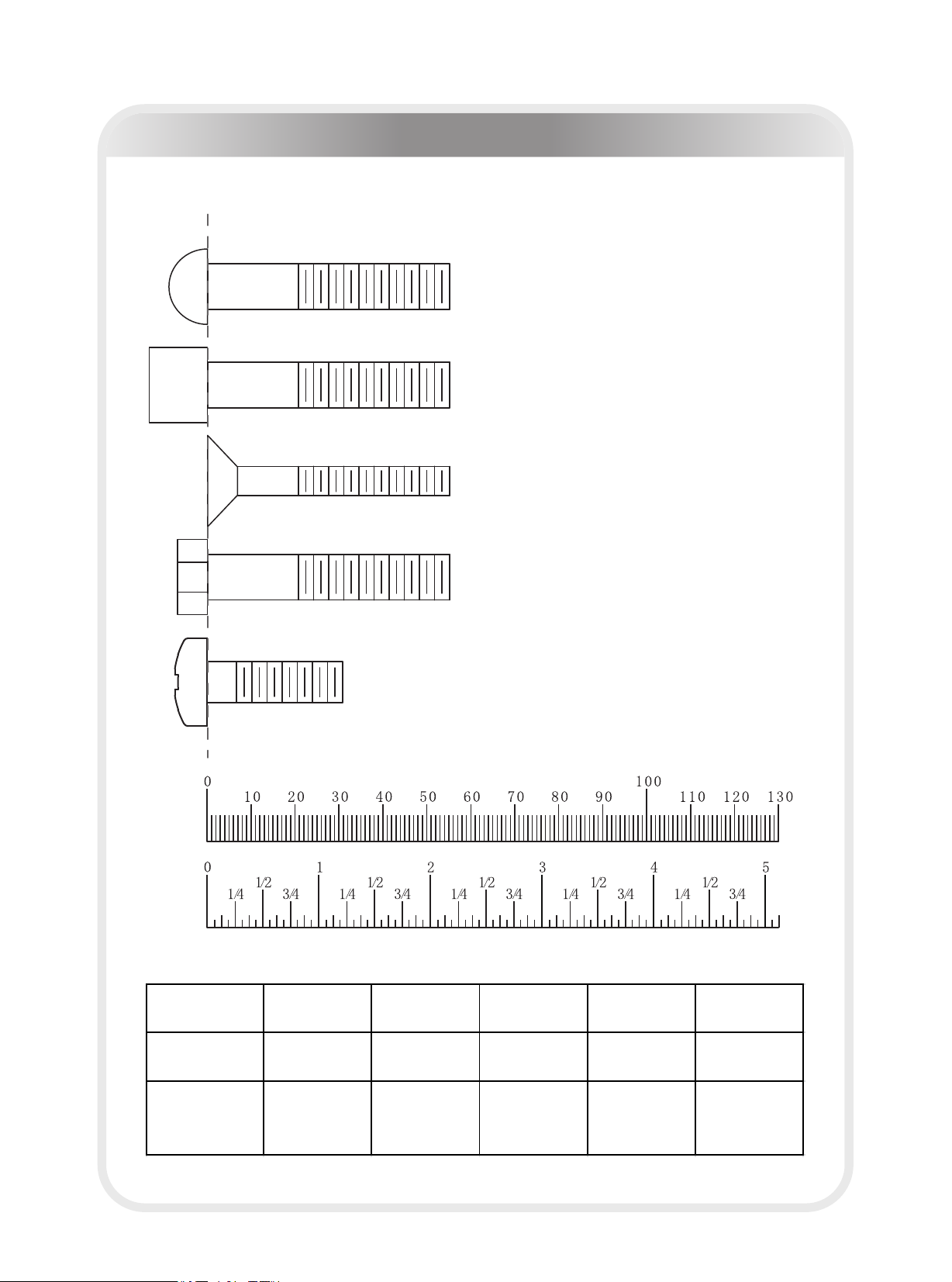
Measurement Guide
Inches
Millimeters
BHCS = Button Head Cap Screw
SHCS = Socket Head Cap Screw
FHCS = Flat Head Cap Screw
HHB = Hex Head Bolt
Diameter of bolt
(mm/inch) M6(1/4") M8(5/16") M10(3/8") M12(1/2") M16(5/8")
Tightening
torque (N.m) 9~12 22~30 45~59 78~104 193~257
Operational
methods for
adult men
The strength of
the wrist
The strength of
the wrist and
forearm
The strength of
the entire arm
The strength of
the arm and
upper body
with all strength
CRPHS = Cross Recessed Pan
Head Screw

─ 9 ─
Assembly of the equipment takes professional installers about 2 hours. If this is
the first time you have assembled this type of equipment, plan to spend more
time. It is strongly recommended to assemble the equipment by professional in-
stallers. You may find it quicker, safer, easier to assemble this equipment with
the help of a friend, as some of components may be large, heavy or awkward to
handle alone. It is important that you assemble your product in a clean, clear,
uncluttered area. This will enable you to move around the product while you are
fitting components and reduce the possibility of injury during assembly.
As with any assembled part, proper alignment and adjustment is critical. While
tightening the fasteners, be sure to leave room for adjustments. Do not fully
tighten the fasteners until instructed to do so. Be careful to assemble the com-
ponents in the sequence presented in this guide.
Assembly Instructions
NOTE

─ 10 ─
Assembly
Step 1
Insert the two Guide Rods (#24) into Rear Base (#1) and secure them in place
using:
two Φ11*Φ20*2 Flat Washer (#102) two Φ10 Spring Washer (#103)
two M10*25 BHCS (#97)
Note: Hand tighten bolts and Mylon Lock nuts until machine is fully assembled.

─ 11 ─
Assembly
Step 2
1. Attach the Seat Pad Support Receptacle (#2) to Rear Base (#1) and secure
in place using:
three M10 Nylon Lock Nut (#104) six Φ11*Φ20*2 Flat Washer (#102)
three M10*75 BHCS (#94) one Φ11*Φ38*2 Flat Washer (#107)
one Φ10 Spring Washer (#103) one M10*80 BHCS (#95)
2. Connect the Front Upright (#86) to Seat Pad Support Receptacle (#2) and
secure together
using:
two M10 Nylon Lock Nut (#104) four Φ11*Φ20*2 Flat Washer (#102)
two M10*80 BHCS (#95)
3. Insert the Pec Dec Mount (#7) onto Seat Pad Support Receptacle (#2) using:
two M10 Nylon Lock Nut (#104) four Φ11*Φ20*2 Flat Washer (#102)
two M10*75 BHCS (#94) one M10*70 BHCS(#93)
one Φ10 Spring Washer (#103) one Φ11*Φ38*2 Flat Washer (#107)
Note: Hand tighten bolts and Νylon Lock nuts until machine is fully assembled.

─ 12 ─
Assembly
Step 3
Install the Main Upright (#3) onto Seat Pad Support Receptacle (#2). Secure it
in place using:
three M10 Nylon Lock Nut (#104) six Φ11*Φ20*2 Flat Washer (#102)
three M10*75 BHCS (#94) two M12*80 BHCS (#98)
one Φ12 Spring Washer (#117) three Φ13*Φ24*1.5 Flat Washer (#101)
one M12 Nylon Lock Nut (#105)
Note: Hand tighten bolts and Νylon Lock nuts until machine is fully assembled.

─ 13 ─
Assembly
Step 4
1. Slide one Weight Stack Bumper (#30) down each Guide Rod (#24). Next, slide
the weight plates down the Guide Rods (#24) in this order - five 15lb Plates
(#36), nine 10lb Plates (#37), five 5lb Plates (#38), and the Top Plate (#27).
2. Insert the Main Top Beam (#4) onto the two Guide Rods (#24) and the Main
Upright (#3).
3. Secure Main Top Beam (#4) to Main Upright (#3) using:
two M12 Nylon Locknut (#105) four Φ13*Φ24*1.5 Flat Washer (#101)
two M12*80 BHCS (#98)
4. Attach the Main Top Beam (#4) to the two Guide Rods (#24) using:
two Φ11*Φ20*2 Flat Washer (#102) two Φ10 Spring Washer (#103)
two M10*25 BHCS (#97)
5. Attach Weight Pin (#31) to Weight Stack.
Note: Hand tighten bolts and Νylon Lock nuts until machine is fully assembled.
─ 14 ─
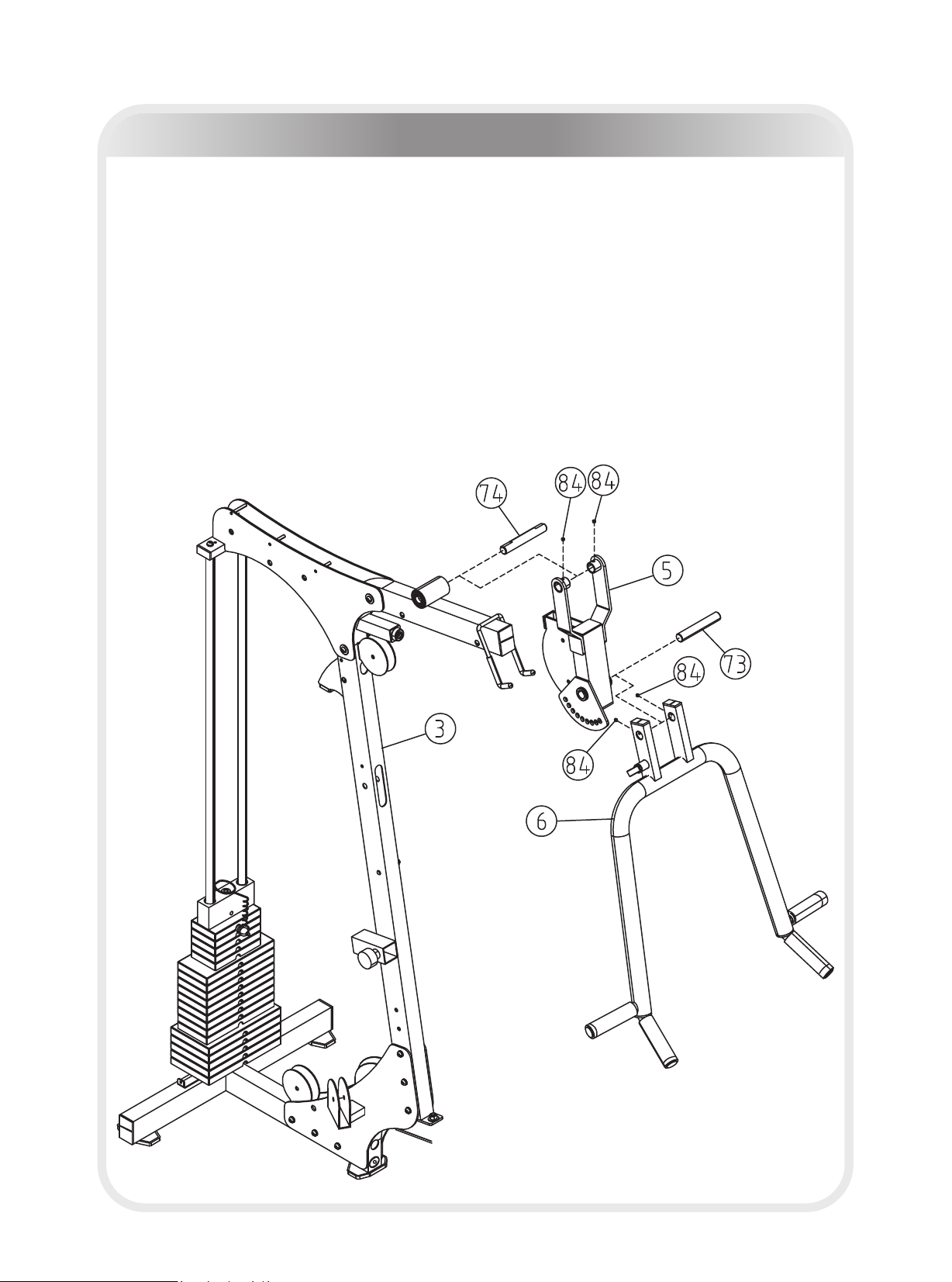
Assembly
Step 5
1. Attach Press Arm Support (#5) to Main Upright (#3) by aligning the holes and
sliding the Shaft (#74) through the holes of the Press Arm Support (#5).
2. Secure the Shaft (#74) to the Press Arm Support (#5) using two M8*6 Socket
Set Screw (#84).
3. Install Press Arm (#6) to Press Arm Support (#5) by aligning the holes and
sliding the Shaft (#73) through the holes of the Press Arm (#6).
4. Secure the Shaft (#73) to the Press Arm (#6) using two M8*6 Socket Set
Screw (#84).
Note: Hand tighten bolts and Nylon Lock nuts until machine is fully assembled.
─ 15 ─
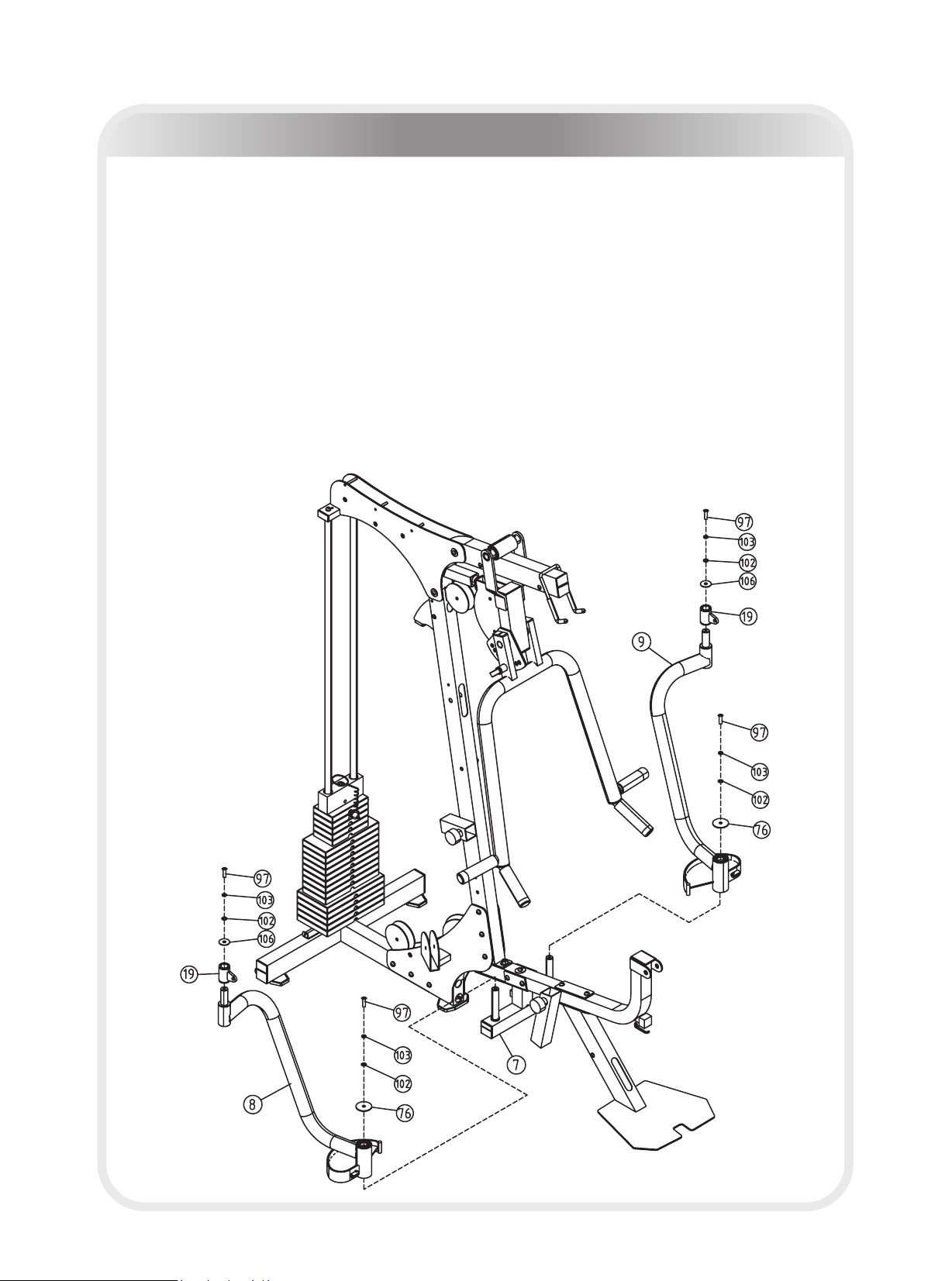
Assembly
Step 6
1. Slide the Right Pec Dec Arm (#8) on to the shaft of the Pec Dec Mount (#7).
Secure the arm in place using:
one Φ56.5*Φ10.5*5 Big Washer (#76) one Φ11*Φ20*2 Flat Washer (#102)
one Φ10 Spring Washer (#103) one M10*25 BHCS (#97)
2. Slide Pec Dec Handle Bar (#19) onto the top of the Right Pec Dec Arm (#8)
and secure using:
one Chrome Washer (#106) one Φ11*Φ20*2 Flat Washer (#102)
one Φ10 Spring Washer (#103) one M10*25 BHCS (#97)
Note: Hand tighten bolts and Nylon Lock nuts until machine is fully assembled.
3. Repeat this step to complete the Left Pec Dec assembly.
─ 16 ─
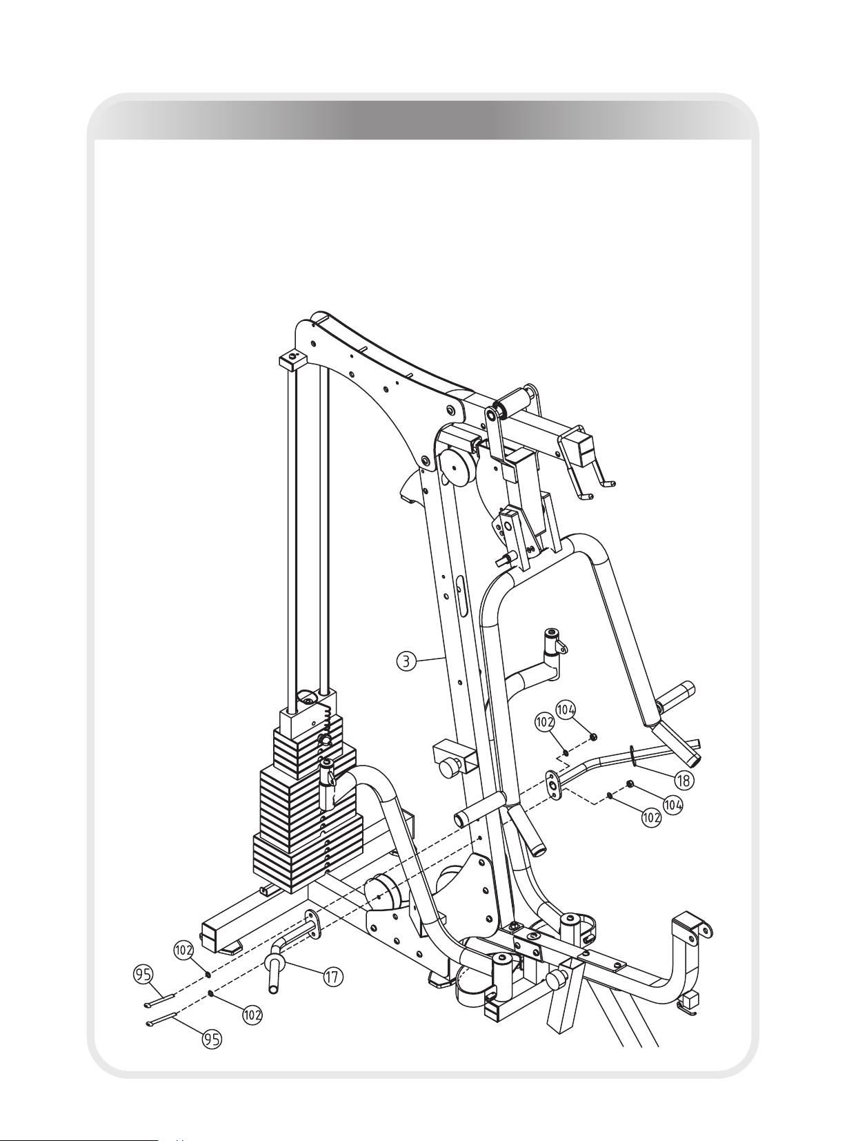
Assembly
Step 7
Install the Right and Left Hold Leg Frames (#17 & #18) to Main Upright (#3) and
secure using:
two M10 Nylon Locknut (#104) four Φ11*Φ20*2 Flat Washer (#102)
two M10*80 BHCS (#95)
Note: Hand tighten bolts and Nylon Lock nuts until machine is fully assembled.
─ 17 ─
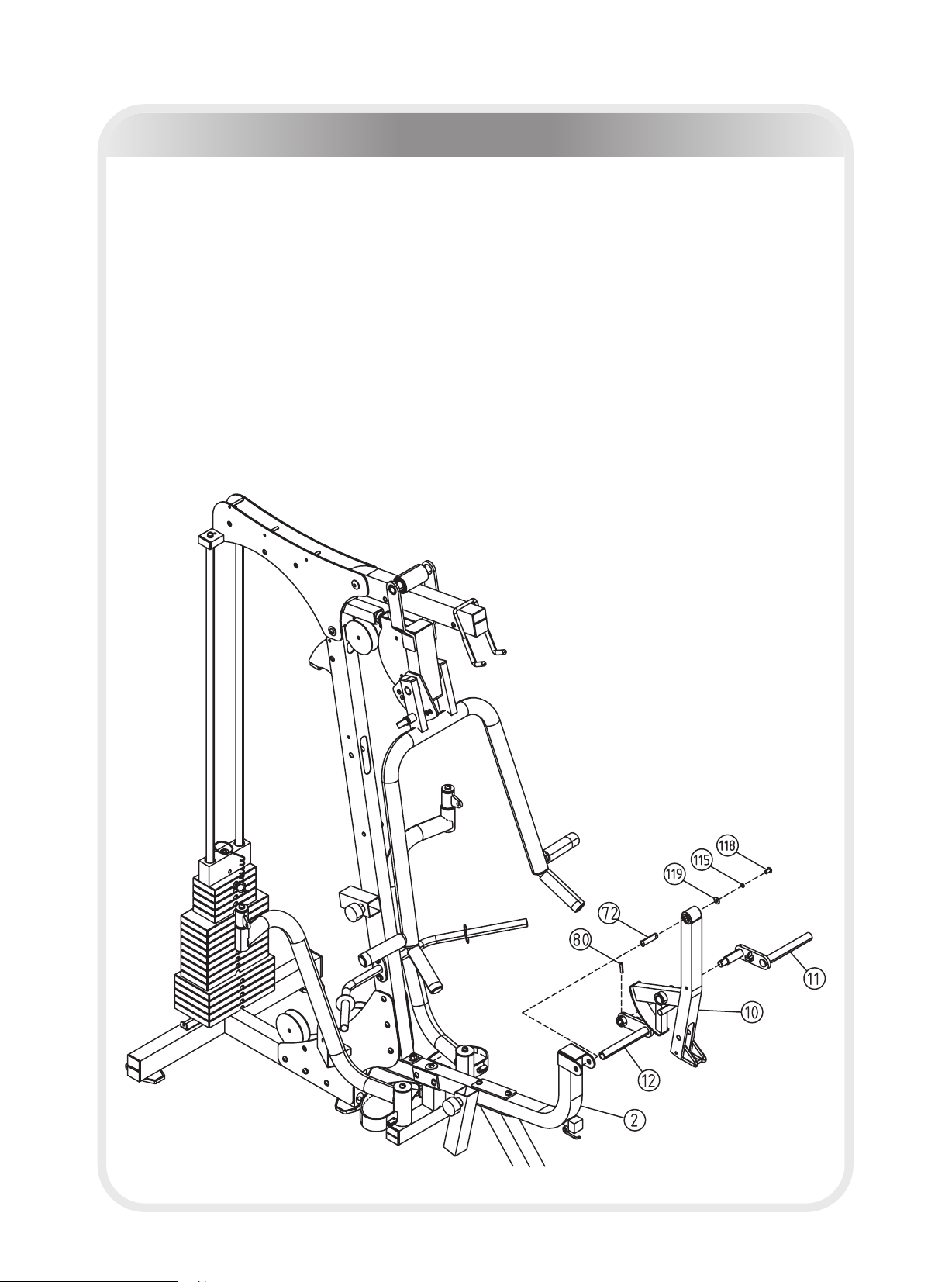
Assembly
Step 8
1. Slide the Shaft (#72) into the Leg Extension Lever (#10). Attach Leg Extension
Lever (#10) to Seat Pad Support Receptacle (#2) and secure using:
one Φ9*Φ22*2 Flat Washer (#119) one Φ8 Spring Washer (#115)
one M8*15 BHCS (#118)
2. Slide Foam Frame w/Shaft (#11) through the Leg Extension Lever (#10) and
attach the Foam Frame w/o Shaft (#12) to the other side. Insert the Slip
Tension Pin (#80) through the hole where the two foam frames meet.
Note: You may need to use a rubber mallet to install Slip Tension Pin (#80).
Note: Hand tighten bolts and Nylon Lock nuts until machine is fully assembled.

─ 18 ─
Assembly
Step 9
1. Attach the Seat Pad (#26) to the Seat Pad Support (#13) using:
two Φ11*Φ20*2 Flat Washer (#102) two M10*50 BHCS (#90)
2. Slide the Seat Support assembly (#13) into the Seat Pad Support Receptacle
(#2) and secure by tightening attached the Locking Pop Pin (#52).
3. Install the Telescope (#14) to the bottom of the Back Pad Support (#16) and
secure in place using:
one M10 Nylon Locknut (#104) one Long Shoulder Bolt (#99)
4. Install the Tilting (#15) to the top of the Back Pad Support (#16) and secure in
place using:
one M10 Nylon Locknut (#104) one Short Shoulder Bolt (#88)
5. Attach the Back Pad (#25) to Back Pad Support (#16) using:
twoΦ11*Φ20*2 Flat Washer (#102) two M10*30 BHCS (#89)
6. Last, slide the Back Pad Support assembly into the receptacle on the Main
Upright (#3) and secure by tightening the Locking Pop Pin (#52).
Note: Hand tighten bolts and Nylon Lock nuts until machine is fully assembled.
─ 19 ─
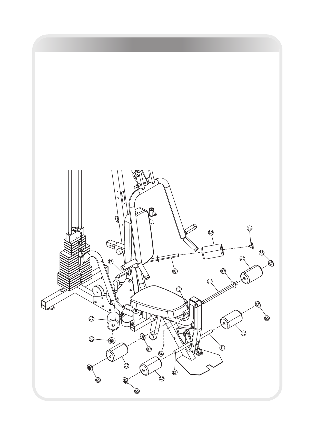
Assembly
Step 10
1. Slide two Upholstered Roller Pads (#42) onto Foam Frames (#11 & #12) and
secure using two Big Plugs (#65).
2. Slide the Long Foam Tube (#77) through the hole in Seat Pad Support (#13)
and secure using one M8*6 Socket Set Screw (#84). Slide two Plastic
Washers (#87) onto each end of Long Foam Tube (#77). Next, slide two
Upholstered Roller Pads (#42) onto each side of Long Foam Tube (#77) and
secure using two Big Plugs (#65).
3. Slide two Upholstered Roller Pads (#42) onto the Leg Hold Frames (#17 &
#18) and secure using two Big Plugs (#65).
Note: Hand tighten bolts and Nylon Lock nuts until machine is fully assembled.

─ 20 ─
Assembly
Step 11
Note: Stretch all cables out completely and make sure all twisting is removed
before installing.
1. Install Chest Press Cable (#45) as detailed in Figure 11. Follow dotted lines
to identify exact location of pulleys. See Page 29 "Cable View" for more detail.
2. Start by threading cable end into Top Plate (#27).
3. You will need the following for installation:
eight Pulley (#44) one Cable (#45)
nine M10 Nylon Locknut (#104) six Long Pulley Spacer (#53)
four Longer Pulley Spacer (#55) one Adjustable Stopper (#75)
two M10*50 BHCS (#90) two M10*45 BHCS (#91)
three M10*70 BHCS (#93) two M10*80 BHCS (#95)
eighteen Φ11*Φ20*2 Flat Washer (#102) one M10 Regular Hex Nut (#100)
one Small Pulley (#120)
Note: Hand tighten bolts and Nylon Lock nuts until machine is fully assembled.
Step 12
Note: Stretch all cables out completely and make sure all twisting is removed
before installing.
Install Mid Pulley Cable (#46) as detailed in Figure 12. Follow dotted lines to
identify exact location of pulleys. See Page 29 "Cable View" for more detail.
Start by installing cable under the pulley at Leg Extension location.
You will need the following for installation:
seven Pulley (#44) one Cable (#46)
eight M10 Nylon Locknut (#104) six Long Pulley Spacer (#53)
four Longer Pulley Spacer (#55) two Short Pulley Spacer (#54)
eighteen Φ11*Φ20*2 Flat Washer (#102) three M10*45 BHCS (#91)
one M10*65 BHCS (#92) one M10*70 BHCS (#93)
one M10*75 BHCS (#94) one M10*80 BHCS (#95)
one Pulley Bracket w/ Shaft (#21) one Pulley Bracket Block (#22)
one Pulley Bracket (#23) one Cable Rtainer Bracket (#78)
one Small Pulley (#120)
Note: Hand tighten bolts and Nylon Lock nuts until machine is fully assembled.
Table of contents
Other TKO Home Gym manuals


