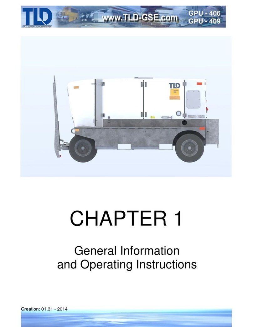
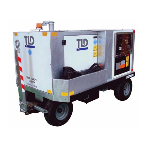
TLD GPU-406 User manual

Creation: 01.31 - 2014
GPU - 406
GPU - 409
CHAPTER 2
MAINTENANCE/MINOR REPAIR
Property of American Airlines

Creation: 01.31 - 2014
GPU - 406
GPU - 409
Contents
1. Periodic Maintenance....................................................................2-1-1
A. Maintenance..................................................................................................................................2-1-2
B. Filters and Lubricants .................................................................................................................... 2-1-3
C. Air Cleaner Maintenance...............................................................................................................2-1-4
D. Engine Fuel ...................................................................................................................................2-1-7
E. Cooling System .............................................................................................................................2-1-8
F. Belts...............................................................................................................................................2-1-9
G. Generator Maintenance.................................................................................................................2-1-9
H. Battery .........................................................................................................................................2-1-10
I. Cables and Cable Heads.............................................................................................................2-1-11
2. Preventative Maintenance............................................................. 2-2-1
A. Engine............................................................................................................................................2-2-1
B. Electrical System (Engine, 24 VDC)..............................................................................................2-2-1
C. Electrical System (Generator, 115 VAC).......................................................................................2-2-2
3. Removal / Installation.................................................................... 2-3-1
A. Engine/Generator Removal/Installation.........................................................................................2-3-2
B. Engine/Generator Coupling/Uncoupling........................................................................................2-3-3
C. Electrical Box Removal/Installation ...............................................................................................2-3-4
D. Radiator Removal/Installation ....................................................................................................... 2-3-4
E. Cable Removal/Installation............................................................................................................ 2-3-5
4. Troubleshooting............................................................................. 2-4-1
A. General Practice............................................................................................................................ 2-4-1
B. Troubleshooting Chart...................................................................................................................2-4-1
Engine and Controls......................................................................................................................2-4-2
Generator and Controls.................................................................................................................2-4-7
#1 Output Load Contactor Operating Circuit...............................................................................2-4-10
#2 Output Load Contactor Operating Circuit (Optional)..............................................................2-4-12
Generator Protective Circuit........................................................................................................2-4-14
28VDC Operating Circuit (Optional)............................................................................................2-4-16
5. Repairs............................................................................................2-5-1
A. Torque Charts................................................................................................................................2-5-1
B. Adjustments................................................................................................................................... 2-5-1
6. Using the Schematics and Connection Diagrams....................... 2-6-1
A. Component Codes.........................................................................................................................2-6-1
B. Schematics and Connection Diagrams.........................................................................................2-6-1
7. GMC2 Setup
A Software Install
B. Procedure: Setup/Initializationv
Property of American Airlines

Creation: 01.31 - 2014
GPU - 406
GPU - 409
This page intentionally left blank
Property of American Airlines

Property of American Airlines

Creation: 01.31 - 2014 2-1-1
GPU - 406
GPU - 409
1. Periodic Maintenance
In order to ensure a properly running unit, periodic maintenance and inspections are necessary. In
addition to the pre-operational instructions given in Chapter 1 the unit must be maintained on a regular
basis and any malfunctions or problems with the unit must be fixed at once. Prolonging repairs on
machinery that is running improperly may create an unsafe situation and will increase mechanical
problems.
When working on any system in the unit, extreme caution must be used to avoid personal injury or
death.
WARNING:
KEEP HANDS AND LOOSE CLOTHING AWAY FROM ROTATING MACHINERY AND BELTS.
WARNING:
ELECTRIC SHOCK MAY RESULT IN SEVERE INJURY OR DEATH. ALWAYS SHUT THE
UNIT OFF AND DISCONNECT THE BATTERY BEFORE PERFORMING ANY MAINTENANCE.
NOTE:
Wet-stacking
Wet-
stacking is common and may be expected in diesel engines operated under light load.
Light loads do not allow the engine to reach the most efficient operating temperature for
complete combustion of fuel. The unburned fuel collects in the exhaust system to create the
condition known as wet-stacking. Wet-
stacking is recognizable by fuel oil wetness around
the exhaust manifold, pipes, and muffler.
To alleviate wet-
stacking in lightly loaded engines, it is recommended that the machine be
connected to a load bank after 200 hours of use and operated under full rated load for one
hour. This will burn away and evaporate the accumulation of fuel in the e
xhaust system.
This clean-
out procedure should be considered as periodic maintenance for machines
operated under light load.
CAUTION:
IF WELDING OR GRINDING ON THE GALVANIZED BASE, SAFETY GLASSES AND A DUST
FILTRATION MASK MUST BE WORN TO PREVENT EXPOSURE TO FUMES AND DUST.
Property of American Airlines

Creation: 01.31 - 2014 2-1-2
GPU - 406
GPU - 409
A. Maintenance
The following charts show the frequency of maintenance required on the listed components.
Component Maintenance Required (1)
Engine air filter Check daily, replace when indicator turns red.*
Engine oil and filter Check daily; change every 500 hours.
Engine fuel filter
Change every 500 Hours
DEF Filter (Tier 4 Final Only)
Change every 4500 hours
Fan belts
Check every 500 hours.
Engine coolant
Check daily; change every 24 months.
Latches and hinges
Lubricate every 300 hours or 6 months
Fuel pre-filter/water separator
Change every 500 hours
Wheels Rotate every 1200 hours or 24 months
Wheel hubs and fifth wheel hub Repack bearings every 24 months
Steam wash engine radiator
250 hours**
Torque wheel lug nuts
500 hours or 6 months
Repack bearings on wheel hubs
and fifth wheel hub 24 months
Inspect cables and cable head(s) 500 hours
* Change as required as shown by visual inspection.
** Always clean radiator from the front nose area of the unit.
(1) This operation should be performed at more frequent intervals under dusty or low temperature
conditions. The time schedules indicated in Chart 1 are approximate. They are based on average
conditions. Reduction of the interval shown may be necessary under harsh operating conditions
such as low engine temperature, excessively heavy loads, and high oil temperatures, or operation
in particularly arid or dusty environments.
LUBRICATION & MAINTENANCE BY HOURS - CHART 1
Property of American Airlines

Creation: 01.31 - 2014 2-1-3
GPU - 406
GPU - 409
B. Filters and Lubricants
Filters and lubricants for periodic maintenance are listed below. The chart includes the name,
GPU part number, and description of the item needed to maintain this unit.
NOMENCLATURE
TLD P/N
CUMMINS
Tier 3
GPU-409/406
TLD P/N
CUMMINS
Tier 4i
GPU-409/406
TLD P/N
CUMMINS
Tier 4 Final
GPU- 409/406
DESCRIPTION
Engine Air Filter 1044786-3
PRIMARY:
Fleetguard
AF55020
1109049
Air Filter
Element
SECONDARY:
Fleetguard
AF55312
1109050
Engine Oil Filter 1033394-P2 1033394-P2
1033394-P2
Spin On Filter
Engine Oil* 1048606
(15w40) 1048606
(15w40)
1048606
(15w40) API CJ-4 or
better oil
Engine Fuel Filter 1037763-P2
Fleetguard
FS19732
1076485-P1
Fuel filter/water
separator
1037763-P1
Fleetguard
FF63004
1076484-P1
Fuel Filter
Diesel Exhaust Fluid N/A N/A
1056783
DEF Fluid
DEF Pump Filter N/A N/A
1076484-P10
DEF Pump
Filter
Engine Coolant 1033604-50 1033604-50
1033604-50
Long Life
Ethylene glycol
Hinge/latch lubricant UMO1-9 UMO1-9
UMO1-9
SAE30 Engine
Oil
Radiator fan/alternator
belt
1037763-P4 1037763-P4
1037763-P4
Poly-V Belt
* This oil is recommended for use in ambient temperatures ranging from 0oF to 120oF.
For information on recommended oil for harsher ambient temperatures consult the Engine
Manufacturer's manual in Chapter 5.
FILTERS & LUBRICANTS
CHART 2
Property of American Airlines

Creation: 01.31 - 2014 2-1-4
GPU - 406
GPU - 409
(1) Lubrication Schedule
The time schedules indicated in Chart 1 are approximate. They are based on average
operating conditions. It may be necessary to reduce the intervals shown when operating the
GPU under harsh operating conditions, such as low engine temperatures, heavy loads, and
high oil temperatures, intermittent operation, or operation in dusty environments.
(2) Engine Oil Specification
Information on engine oil specification is contained in the Manufacturer's Literature in Chapter
5. The use of the proper engine oil is critical in Tier 4 engines to ensure a long life of the
catalyst.
(3) Oil Viscosity
The use of 15W-40 grade oil is recommended for year-round service. Additional information
is contained in the Engine Manufacturer's Manual, in Chapter 5.
(4) Changing Engine Oil
Follow the instructions contained in the Manufacturer’s Manual.
(5) Changing Engine Oil Filter
Follow the instructions in the Manufacturer's Manual.
C. Air Cleaner Maintenance
The air filter contains a replaceable element (refer to Chart 1). A definite time schedule for
changing the element cannot be determined because of varying operating conditions. Check the
filter daily and change the element as required.
(1) Air Filter Replacement
(a) Turn off the unit battery switch and open the doors on the left side of the unit.
(b) Remove the rear half of the air filter housing by rotating the end cap to the ‘unlock’
position (Tier3) or unclipping two latches on the air filter housing (Tier 4).
(c) Remove the air filter element and discard. Clean out the dust trap on the air filter.
(d) Install a new air filter element.
(e) Reinstall the rear half of the air filter housing and secure it by rotating the end cap to the
‘lock’ position (Tier 3) or snapping in two latches (Tier 4)
(f) Close the doors on the unit.
CAUTION:
DO NOT ATTEMPT TO CLEAN OR REUSE THE AIR FILTER
ELEMENT.
Property of American Airlines

Creation: 01.31 - 2014 2-1-5
GPU - 406
GPU - 409
Tier 4 Final Engines
The Tier 4 Final engine air cleaner assembly consists of replaceable primary and secondary air filter
inside a plastic housing. It is designed to be maintained without tools. Refer to Table 2to see the
necessary parts for the maintenance of the air cleaner. A definite time schedule for changing the
element cannot be determined because of varying operating conditions. Check the filter indicator
daily and change the element as required.
Air Filter Replacement
1. Turn off the unit battery switch and open the doors on the left side of the unit.
2. Remove the air flow straightener (Refer to Figure 1C: Tier 4 Final Engine Air Cleaner).
This is done by pulling on the latches on the left and right of the air cleaner assembly and
pulling the straightener away from the air cleaner.
3. Once the flow straightener is removed, the inlet cover is exposed. Remove the inlet cover by
unlatching the 4 metal latches on the right side of the cover and pulling the cover away from
the air cleaner.
4. The primary air filter can now be pulled out. Remove the primary air filter to expose the
secondary air filter.
5. Before removing the secondary air filter, make sure there is no debris left inside the air
cleaner. Remove and replace the secondary air filter if it is necessary. Replace it by pushing
the filter straight into the air cleaner housing until the gasket on the filter seats properly.
6. Replace the primary air filter by pushing the filter straight into the air cleaner housing until
the gasket seats properly.
7. Replace the air inlet cover by moving the cover into place and latching the four metal
latches.
8. Replace the air flow straightener by locating the plastic locking tabs and pressing firmly on
the cover to snap it in place.
CAUTION:
DO NOT ATTEMPT TO CLEAN OR REUSE THE AIR FILTER
ELEMENT.
Property of American Airlines

Creation: 01.31 - 2014 2-1-6
GPU - 406
GPU - 409
FIGURE 1A
TIER 3 AIR FILTER
FIGURE 1B
TIER 4I AIR FILTER
END CAP
LATCHES
Property of American Airlines

Creation: 01.31 - 2014 2-1-7
GPU - 406
GPU - 409
FIGURE 1C
TIER 4 FINAL AIR FILTER
D. Engine Fuel
(1) Quality
Use of Grade 2 diesel fuel is recommended. The use of low sulfur diesel fuel allows for 500
hour oil change intervals. Use of high sulfur diesel fuel shortens the oil change interval for the
engine. Tier 4 engines MUST be operated only on PURE Ultra Low Sulfur diesel fuel (<15
mg/kg / <15 PPM), use of any other fuel will damage the catalyst permanently and void the
engine warranty. Further information on fuel specifications can be found in the Engine
Manufacturer’s Manuals.
(2) Fuel Filter
Refer to the Manufacturer's Literature in Chapter 5 for information on removal and
replacement of the fuel filter elements.
Secondary Cyclonic Stage
WARNING:
The use of non-low sulfur diesel fuel or any type of jet fuel in any
unit equipped with a Tier 4 (Stage 3B/Stage4) engine will cause
permanent damage to the engine catalyst and void the engine
warranty.
4 Metal Latches
Dust Evacuator
Property of American Airlines

Creation: 01.31 - 2014 2-1-8
GPU - 406
GPU - 409
E. Cooling System
Permanent long-life type (ethylene glycol) antifreeze is recommended for use in the cooling
system. It must be ethylene glycol type, contain no more than 0.1% anhydrous metasilicate, and
meet General Motor's performance specification GM1899M or be formulated to GM6038M
specification (or equivalent). Further information on coolant requirements may be found in the
Manufacturer's Literature in Chapter 5.
WARNING:
DO NOT USE METHYL ALCOHOL BASE ANTIFREEZE.
DO NOT USE METHOXY PROPANOL ANTIFREEZE.
DAMAGE MAY OCCUR TO THE RUBBER SEALS ON THE
CYLINDER LINERS, WHICH ARE IN CONTACT WITH THE
COOLANT.
Property of American Airlines

Creation: 01.31 - 2014 2-1-9
GPU - 406
GPU - 409
F. Belts
A single poly-V belt driven by the engine crankshaft pulley is used to drive the battery charging
alternator, the radiator fan, and the engine coolant pump. The belt system is equipped with an
automatic tensioner which eliminates the need for periodic tensioning. The belt must be inspected
on a regular basis and replaced when excessive stretch or cracking are present.
The belt is replaced as follows:
1. Turn off the unit battery switch
2. Open the doors to the unit on both sides for access.
3. Remove the overflow bottle from alternator guard on the left side of the unit and set it
aside carefully.
4. Remove the alternator guard.
5. Remove the fan guard from the radiator.
6. Rotate the tensioner to relieve tension on the drive belt and, while holding tensioner,
remove the belt from the alternator pulley.
7. Release the tensioner.
8. Make note of the routing of the belt and remove it from the pulleys.
9. Remove the belt by moving it over the fan blades.
10. Installation is the reverse of the removal.
G. Generator Maintenance
The 400 Hz generator requires no maintenance or service other than periodic cleaning. Refer to
the specific generator manual in chapter 5 for more information.
(1) Cleaning
When inspection determines that cleaning is necessary, clean the generator as follows.
(a) Wipe loose dirt from the exterior painted surfaces with a clean lint-free cloth. Remove
stubborn accumulations of dirt with an approved detergent or solvent. Clean all ventilating
parts with a vacuum cleaner or filtered compressed air at a pressure of 25 to 40 psi.
(b) Clean the inside of the generator with a vacuum cleaner or use dry filtered air at a
pressure of 25 to 40 psi. Remove stubborn accumulations of dirt and grease from
windings with naphtha.
(c) Clean electrical contacts such as relay contacts, switch contacts, and terminals with an
approved contact cleaner.
WARNING:
USE EXTREME CARE WHEN USING NAPTHA. USE ONLY IN
WELL VENTILATED AREAS, AWAY FROM OPEN FLAMES AND
SPARKS.
NOTE:
Do not file contacts.
Property of American Airlines

Creation: 01.31 - 2014 2-1-10
GPU - 406
GPU - 409
(2) Adjustment
The generator itself requires no adjustments.
H. Battery
Two 12 volt batteries wired in series produce a 24 VDC system which supplies power for operation
of the engine electrical system and the clearance and panel lights.
(1) Battery Location
The batteries are located on the left side of the unit by the generator. The batteries are easily
accessible for checking and maintenance.
FIGURE 2
BATTERY LOCATION
Property of American Airlines

Creation: 01.31 - 2014 2-1-11
GPU - 406
GPU - 409
(2) Battery Care
(a) Maintain battery in fully charged condition.
(b) Ensure battery is fastened securely to prevent damage.
(c) Maintain battery fluid at the proper level.
(d) Keep the battery terminal posts and clamps clean.
(3) Liquid Level
The electrolyte level in each cell should be above the plates at all times to prevent battery
failure. When the electrolyte level is low, add pure distilled water. Do not use hydrant water
or any water that has been in contact with a metal container.
I. Cables and Cable Heads
(1) Cables
Inspect cable for any insulation damage, frayed copper, and any overheated areas. If any of these
are found, the cable should be replaced.
(2) Cable Plugs
(a) Inspect the plug for wear. Replace it as needed.
(b) Inspect the sockets in the plug for wear, evidence of arcing, and burn marks. Replace plug
assembly as needed.
(c) Verify that the bolts holding cables to the plug are tight
WARNING:
NEVER ALLOW SPARKS OR OPEN FLAME TO COME NEAR
THE BATTERY. AVOID SPILLING ELECTROLYTE ON HANDS
OR CLOTHING.
CAUTION:
ALL GPU POWER CABLES AND HEADS WEAR OUT OVER TIME.
FAILURE TO INSPECT CABLES AND HEADS CAN LEAD TO UNIT,
AND/OR AIRCRAFT DAMAGE.
Property of American Airlines

Creation: 01.31 - 2014 2-1-12
GPU - 406
GPU - 409
J. Diesel Exhaust Fluid – Tier 4 Final Only
DEF must be replaced periodically as it is consumed during operation. Determine if
replenishment of the DEF is necessary by reading the gauge displayed on the generator
controller.
Fill the DEF tank by pouring ISO-compliant DEF or AdBlue into the fill port indicated with the
“DEF or AdBlue” label and the blue cap. Avoid overfilling the DEF tank by watching the
gauge on the generator controller screen, and stopping the fill when the gauge reaches
100%.
Figure 3: DEF Fill Port Location
NOTE:
When DEF level falls below 2.5% of the maximum capacity,
engine power output will be reduced to comply with emission
regulations. This may cause an interruption in power delivery to
attached aircraft.
DEF Fill Port
Property of American Airlines

Creation: 01.31 - 2014 2-1-13
GPU - 406
GPU - 409
This page intentionally left blank
Property of American Airlines

Property of American Airlines

Creation: 01.31 - 2014 2-2-1
GPU - 406
GPU - 409
2. Preventative Maintenance
A. Engine
(1) Fuel
(a) Check fuel level daily.
(b) Check fuel filters and change elements in accordance with the instructions in the
Manufacturer's Literature in Chapter 5.
(c) Open the fuel tank drain every 500 hours to drain off water and sediment.
(2) Lubrication
(a) Check the crankcase oil level daily.
(b) Lubricate hinges in accordance with the Lubrication & Maintenance Chart 1 on Page 2.
(3) Coolant
(a) Check coolant level daily.
(b) Inspect for signs of rust or corrosion. Inspect for signs of leakage. Inspect hoses for
deterioration or cracking.
(4) Exhaust System
(a) Inspect muffler and pipe-work for signs of approaching failure.
(b) Check for any gasket or joint leaks.
(5) Exhaust Aftertreatment System (Tier 4 Final Only)
(a) Inspect the DEF injection system for leaks of coolant or DEF.
(b) Check DEF level daily.
B. Electrical System (Engine, 24 VDC)
(1) Lights
Check all lights for correct operation daily. Replace any defective bulbs as soon as they are
discovered.
(2) Wiring and Connections
Inspect all cables and leads for broken, worn or damaged insulation. Check electrical
connections for tightness.
Property of American Airlines

Creation: 01.31 - 2014 2-2-2
GPU - 406
GPU - 409
C. Electrical System (Generator, 115 VAC)
The 400 Hz generator and controls are designed to be maintenance-free. No periodic
maintenance adjustments are necessary. However, regular checks should be made to be sure all
controls, instruments, etc. are working correctly.
(1) Monitoring Instruments
Ensure the Generator Control Module’s display is in proper working condition each time the
unit is started.
(2) Protective Circuits
Check operation of all protective modules to be certain they will function in the event of a fault
in the output circuit.
(3) Wiring and Connections
(a) Check all cables, leads and wiring for broken, worn, or damaged insulation.
(b) Check all connections for tightness.
Property of American Airlines
Other manuals for GPU-406
1
This manual suits for next models
1
Table of contents
Other TLD Portable Generator manuals
Popular Portable Generator manuals by other brands
Peak Scientific
Peak Scientific Precision Series user manual
VICI DBS
VICI DBS NM PLUS user manual
Powermate
Powermate PM0123250 Operator's manual
Firman
Firman P05703 owner's manual
Chamberlain
Chamberlain LiftMaster PROFESSIONAL 475LM owner's manual
National Instruments
National Instruments NI PCI-6542 Getting started guide
