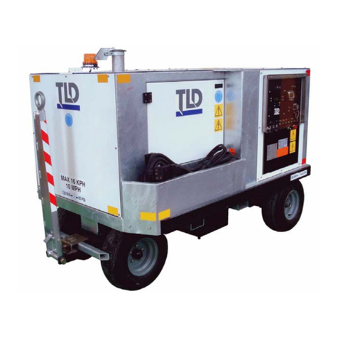
TLD GPU-406 Operating instructions

Creation: 01.31 - 2014
GPU - 406
GPU
-
409
CHAPTER 1
General Information
and Operating Instructions

Creation: 01.31 - 2014
GPU - 406
GPU
-
409
Contents
ContentsContents
Contents
INFORMATION ................................................................................... 1-1-1
1.
Unit Description ............................................................................................................................. 1-1-1
A.
GPU-406 and GPU-409 ........................................................................................................... 1-1-1
2.
Major Component Description ....................................................................................................... 1-1-7
A.
Engine ...................................................................................................................................... 1-1-7
B.
Generator System .................................................................................................................... 1-1-8
3. Electrical Box Assembly ............................................................................................................... 1-1-10
A. Relay Panel Assembly ............................................................................................................ 1-1-11
B. Relay Panel Components ....................................................................................................... 1-1-12
C.
Generator Control Module...................................................................................................... 1-1-14
D.
Instrument Panel .................................................................................................................... 1-1-16
E.
Contactors .............................................................................................................................. 1-1-22
Operation............................................................................................ 1-2-1
Specifications and Capabilities ........................................................ 1-3-1
Shipping ............................................................................................. 1-4-1
Storage ............................................................................................... 1-5-1

Creation: 01.31 - 2014
1-1-1
GPU - 406
GPU
-
409
INFORMATION
1. Unit Description
A. GPU-406 and GPU-409
The GPU-406 and GPU-409 are self-contained, diesel engine-driven, ground power units. The units
are designed to supply regulated 400 Hz electrical power to a parked aircraft for operation of the
aircraft's electrical equipment when the on-board generators are not running. The components of the
GPU-400 series are of a simple but rugged design with sufficient safety devices to ensure a long,
trouble-free service life. The illuminated control panel and backlit LCD display provide for easy night
operation.
The ground power units feature a brushless-revolving-field generator, rubber-torsion-axle-mounted
chassis of rugged galvanized steel construction with fifth-wheel steering, powder-coated sheet metal
panels, and fiberglass housings. TLD GPU’s can be equipped to meet Tier 3 (Stage IIIA) or Tier 4
Final (Stage IV) emissions standards.
Options available on the GPU-400 ground power units are listed below. Each piece of optional
equipment is covered by its own instructions and parts breakdown, and is located in Chapter 4.
Disregard the option if it is not applicable to your unit.
(1) Low fuel warning with shutdown or idle
(2) Low fuel warning
(3) Engine block heater (120 VAC or 240 VAC)
(4) Amber or red, flashing, non-flashing, or rotating warning beacon
(5) 28.5 VDC transformer-rectifier (TR) package with current limiting, rated at 600 amps continuous
and 2500 amps peak output
(6) 2nd 400 Hz output
(7) Fuel filter / water separator with heater
(8) Plastic rub rails

Creation: 01.31 - 2014
1-1-2
GPU - 406
GPU
-
409
1...Air filter
2...Exhaust silencer
3...Charge air cooler
4...Engine
5... Radiator
6...Generator
GPU-406 AND GPU 409
CUMMINS TIER 3 ENGINE CONFIGURATION
FIGURE 1
6
5
4
3
2
1

Creation: 01.31 - 2014
1-1-3
GPU - 406
GPU
-
409
1...Air filter
2...Charge air cooler
3...Engine
4... Radiator
5...Generator
6…Diesel Oxidation Catalyst
GPU-406 AND GPU 409
CUMMINS TIER 4 INTERIM ENGINE CONFIGURATION
FIGURE 2
1
2
3
5
6
4

Creation: 01.31 - 2014
1-1-4
GPU - 406
GPU
-
409
GPU-406 AND GPU 409
CUMMINS TIER 4 FINAL ENGINE CONFIGURATION
FIGURE 3
1…Air filter
2…Charge air cooler
3…Engine
4…Radiator
5…Generator
6…DOC (Diesel Oxidation Catalyst)
7…DRT (Decomposition Reactor Tube)
8…SCR (Selective Catalytic Reducer
1
2
3
4
5
6
7
8

Creation: 01.31 - 2014
1-1-5
GPU - 406
GPU
-
409
1...Fuel Overflow Vent
2...Fuel Tanks
3...Fuel Fill
GPU-406 AND GPU 409
FUEL SYSTEM
FIGURE 4
2
3
1

Creation: 01.31 - 2014
1-1-6
GPU - 406
GPU
-
409
TLD LINK
FIGURE 5
1…Antenna
2…Telematics Module
3…SIM card (inside the telematics module)
TLD Link
TLD Link allows for remote monitoring of the units’ status in the field using the TLD Link portal from
TLD’s main homepage via phone, tablet, or personal computer.
TLD Link consists of 3 main components
1. Antenna
oSends and receives information from and to the server; mounted on the top of the unit
2. Telematics Module
oProcesses unit status and the GPS location; mounted at the side of the electrical box,
opposite side of the connection plug
3. SIM card
oUnique for each unit, SIM card contains authentication for communicating between the unit
and the server; located inside the telematics module, SIM card can be accessed by
removing the slot connector
1
2
3

Creation: 01.31 - 2014
1-1-7
GPU - 406
GPU
-
409
2. Major Component Description
For the purposes of orientation and to familiarize operators and maintenance personnel with the location of
components, the radiator is considered to be at the front of the unit. The generator and controls are at the
rear. Right and left are determined by standing at the rear end facing the instrument panel.
A. Engine
The GPU-400 series is equipped with a 4-cylinder, in-Iine, turbocharged engine, certified to meet EPA
Tier 3 and Euro COM 3A emissions regulations. Tier 4 Final and Euro Stage IV compliant engines are
also available.
All engines used are equipped with electronic governors, which provide precise frequency regulation
and fast transient response. Engine protection such as low oil pressure, high coolant temperature, and
over speed protection are programmed into the engine electronic control module. An engine
diagnostic connector is provided for communicating with the engine. Full-flow fuel and lubrication oil
filters are utilized.
A 24-volt starting motor and alternator are used, as well as a heavy duty spark arresting exhaust
silencer and dry-type air cleaner. The fan is a pusher type, which sucks the air into the unit through
the bottom, underneath the generator, and pushes it across the radiator and turbocharger air cooler,
and finally out the roof of the unit.
REFER TO CHAPTER 5, CUMMINS QSB OPERATION AND MAINTENANCE MANUAL FOR MORE
INFORMATION ON THE ENGINE.
B. Aftertreatment System
The Tier 4 Final engine is equipped with a special exhaust system that treats the emitted exhaust gas
from the diesel engine to reduce harmful emissions. The exhaust system processes the exhaust gas
by first passing it through a Diesel Oxidation Catalyst (DOC) to reduce unburnt hydrocarbon and CO
emissions. Then, the exhaust gas passes through a Selective Catalytic Reactor (SCR) which, along
with the Diesel Exhaust Fluid (DEF), reduces NO
X
emissions.
The parts that support the SCR include the DEF supply module, heater lines, and DEF tank. These
parts aim to regulate the temperature and delivery of DEF to the exhaust system. Refer toError!
Reference source not found. Figure 9 for more detail.
FRONT
REAR

Creation: 01.31 - 2014
1-1-8
GPU - 406
GPU
-
409
C. Generator System
The generator system is a simple system which contains few components. The unit utilizes a TLD
brand generator. The other major assembly of the generator system is the electrical box assembly,
which contains the generator control module, instrument panel controls, and a relay panel.
Generator:
The 400 Hz generator is a brushless, revolving-field, three-phase, synchronous, alternating-current
generator of single-bearing construction. Generator excitation current is supplied from a directly-
connected brushless rotating D.C. exciter. The generator stator core is constructed of one-piece steel
laminations. The steel laminations are assembled under pressure to form the stator core. The
assembled core is rigidly welded to the frame ribs, and heavily-insulated stator coils of the highest-
quality magnetic copper are then inserted in the stator slots. The stator core slots are insulated with
the highest-quality insulating material.
The generator field poles are mounted on a large-diameter shaft. Field coils of heavily insulated wire
are wound directly onto the poles. The coils are blocked and braced for physical strength and rigidity.
The exciter armature and rotating rectifier bridge assembly are sleeve-mounted on the shaft of the
synchronous generator. The rotating rectifier assembly consists of a full-wave rectifier bridge made up
of six semiconductor devices in a potted enclosure.
The generator‘s brushless exciter is an inverted synchronous AC generator with the field winding
stationary and the three-phase armature windings rotating with the generator rotor. The stationary
exciter field (stator) is designed to be the primary source of the generator’s residual magnetism. This
residual magnetism allows the exciter armature (rotor) to produce AC voltage even when the exciter
field (stator) is not powered. This AC voltage is rectified to DC by the rotating rectifier assembly and
fed directly to the main field (rotor). As the generator shaft continues to rotate, the main field (rotor)
induces a voltage into the generator’s main armature (stator).
The voltage regulator is powered by the GPU diesel engine’s charging system. This system of using
an external voltage source to provide the excitation current for the generator eliminates the need for a
special field flashing circuit in the regulator.
The generator is designed with a self-contained cooling system which circulates cool air through the
machine. Ambient air is drawn into the machine through louvered openings at the exciter end of the
machine by a large capacity blower. The warm air is exhausted to the atmosphere through the
screened opening enclosing the blower assembly. The complete generator is bolted to the engine
flywheel housing.
Generator electrical characteristics:
-Phase imbalance: Not to exceed 1% at balanced 3- phase load. Not to exceed 4% at 1/3
load on 1 phase and no-load on the other 2 phases.
-Harmonic content: Total harmonic distortion not to exceed 2%. Any single phase
harmonic not to exceed 1.5% at 0.8 P.F. linear load.
-Crest factor: 1.414 +/- 0.007
-Frequency regulation: +/- 0.1% no-load to full-load and overload.
- Frequency transient: +/- 2.5% no-load to full load
- Frequency transient recovery time: +/- 0.5% of nominal frequency within 1.5 seconds.
- Overload rating: 125% for 5 minutes.

Creation: 01.31 - 2014
1-1-9
GPU - 406
GPU
-
409
1…Louvered panel 13...Shim Plates
2…Screen Cover 14...Drive Plates
3...Exciter Stator 15...Ring
4...End Bell 16...Ring
5…Main Stator 17...Screen Cover
6...Cover Plate 18...Key
7…Bridge Rectifier 19...Key
8…Exciter Rotor 20...Transition Segment
9…Bearing 22...Cover Plate, Exciter
10…Main Rotor 23...Screw
11...Cooling Fan 24...Cover, End Bell
12...Fan Seat 25…Screen
GENERATOR BREAKDOWN
FIGURE 5

Creation: 01.31 - 2014
1-1-10
GPU - 406
GPU
-
409
3. Electrical Box Assembly
The electrical box assembly is located at the extreme rear of the unit and houses the instrument panel
and the relay panel.
FIGURE 6
1…Electrical Box
2…View Screen
3…Select Buttons
4…Control Knob
5…Emergency Stop (E-Stop)
6…Electrical Panel
7…GCM2 Control Box
FIGURE 7
ELECTRICAL BOX ASSEMBLY
1
2
3
4
7
5
6

Creation: 01.31 - 2014
1-1-11
GPU - 406
GPU
-
409
A. Relay Panel Assembly
The relay panel assembly is mounted inside the electrical box on the back wall. The relay panel
provides mounting facilities for engine and generator control and protection relays, 3 current
transformers, and output load contactor(s).
RELAY PANEL
FIGURE 8
1…Current Transformers – T1, T2, T3 8…Engine Running Relay – K3
2…Contactor(s) – K16 (K17 is optional) 9…Key Switch Power Relay – K10
3…Generator Neutral Distribution Block – TB2 10…Low Fuel Relay – K5
4…400Hz Control Signal Terminal Blocks – TB8 (TB10
is optional and not shown)
11…J1939 Data Link Connector – P11
5…Battery Ground Terminal Block – TB5
6…Switched +24V Terminal Block – TB3
7…Battery Power Terminal Block – TB7
1
6
5
8
11
3
TB2
2
7
10
9
4
T3
T1
T2 K3
K16
K5
K10
K17

Creation: 01.31 - 2014
1-1-12
GPU - 406
GPU
-
409
B. Relay Panel Components
(1) Current Transformers – T1, T2, T3
The relay panel assembly contains 3 current transformers which send current signals from the
three phases to the Generator Control Module (GCM) for load sensing and line drop
compensation, for instrument panel indication, and for over-current protection. The transformer
converts current readings at a ratio of 400:5; that is, for every 80A of output current, 1A of
sensing current flows through the GCM. For 180 KVA units, this ratio is 600:5.
(2) Contactor(s) – K16, K17
The function of the contactors is to allow, or not allow, 400 Hz output power from the generator to
the aircraft. The contactor states, open or closed, is controlled by the 24 VDC contactor coil.
GPU-406 and GPU-409 have (1) contactor as standard and a 2nd is included with the optional
2nd 400 Hz output.
(3) Generator Neutral Distribution Block – TB2
The purpose of the neutral distribution block is to provide a means to connect the generator
neutral to the aircraft neutral through a cable. TB2 is for connecting the 400 Hz output cable(s)
Neutral wire “N” to the Generator “N” cable.
(4) 400Hz Control Signal Terminal Blocks – TB8, TB10
TB8 and TB10 connect the E and F pins of the 400Hz AC output cable to the generator
controller module (GCM). This provides the GCM with a 28 Volt Signal once the aircraft has
accepted power from the GPU. TB10 provides the signal for AC Output #1, while TB8 (optional)
provides the signal for AC Output #2.
(5) Battery Ground Terminal Block – TB5
TB5 provides the ground connection for all components inside the electrical box. It is connected
directly to the battery negative terminal.
(6) Switched +24V Terminal Block – TB3
TB3 provides 24V power when the GPU is turned on for all components inside the electrical
box. It is connected to a relay that is active after the GPU is turned on with the green power
button, or after it wakes up when the battery switch is engaged.
(7) Battery Power Terminal Block – TB7
TB7 provides battery power to components inside the electrical box. It is directly connected to
the battery positive terminal.
(8) Engine Running Relay – K3
The purpose of a relay is to provide a controlled connection. A relay is also used to connect a
high-power circuit by using a low-power circuit to control the connection. K3 is the engine

Creation: 01.31 - 2014
1-1-13
GPU - 406
GPU
-
409
running relay. Its function is to provide a 24V signal when the engine is running above 600 RPM.
This signal is used to power an analog engine hourmeter.
(9) Key Switch Power Relay – K10
K10 is the key switch power relay. This relay provides 24V power to all the components
connected to TB3 (switched +24V terminal block). It is only active after the GPU has turned on.
The engine control module (ECM) requires the 24V signal that this relay provides to allow the
engine to run.
(10) Low Fuel Relay – K5
K5 is the low fuel relay, and it is only present when the GPU has been optioned with a low fuel
warning beacon. This relay provides power to the low fuel warning beacon when the fuel level
has reached its low limit.
(11) J1939 Data Link Connector – P11
P11 is the Data Link Connector. Its purpose is to provide a way to communicate with the engine
control module (ECM) for diagnostic purposes.

Creation: 01.31 - 2014
1-1-14
GPU - 406
GPU
-
409
C. Generator Control Module
The generator control module is mounted inside the door of the GPU’s electrical box. Its display
is read without opening up the electrical box.
GENERATOR CONTROL MODULE
FIGURE 9
The Generator Control Module (GCM) is the brain of the GPU-400. It is a fully-automatic voltage
regulator that not only provides voltage and frequency regulation, but also generator fault protection
and generator power output display. The GCM also functions as an engine instrument panel that can
display engine fault codes, and other useful information such as charging voltage and engine RPM. On-
screen directions in multiple available languages guide the operator on how to properly operate the
GPU.
The GCM monitors the 400 Hz output when 400 Hz is in use and automatically switches over to
monitor the 28.5 VDC output when the optional 28.5 VDC transformer-rectifier is in use. The GCM
provides line drop compensation on 400 Hz as well as line drop compensation and current limiting on
the 28.5 VDC transformer-rectifier. The GCM displays the generator output voltage, current, and
frequency on a backlit LCD. The voltage regulator is programmed to protect against the following
generator fault conditions:

Creation: 01.31 - 2014
1-1-15
GPU - 406
GPU
-
409
-Over-frequency: AC Output is over 420 Hz for 5 seconds
-Under-frequency: AC Output is under 380 Hz for 7 seconds
-Over voltage: AC Output is over 130 volts for 2 seconds
-Under voltage: AC Output is under 100 volts in 7 seconds
-Overload: Output is over 125% of rated capacity for 5 minutes
The voltage regulator displays and latches the fault if any of the above should occur.
Power is automatically disengaged from the aircraft.
Generator Control Module Characteristics:
The following are the electrical characteristics of the Generator Control Module:
-Voltage regulation: +/- 1% maximum over full range of generator loading.
-Voltage transient: 13.8% no load to full load.
-Voltage transient recovery time: +/- 1% of nominal voltage within 100 milliseconds.
-Voltage modulation: 0.5% at steady state.
- Line drop compensation: Provides a voltage increase of up to 10 volts, line to neutral, to
compensate for voltage drop in the aircraft cable assembly.

Creation: 01.31 - 2014
1-1-16
GPU - 406
GPU
-
409
D. Instrument Panel
The GPU’s instrument panel is located at the rear extreme of the unit. It provides the operator with controls and
displays for generator and engine functioning.
INSTRUMENT PANEL
FIGURE 10
1…Blue Button
2…Red Button
3…Yellow Button
4…Green Button
5…Dial with Pushbutton
6…LCD Screen
7…Emergency Stop
4
1
2 3
5
7
6

Creation: 01.31 - 2014
1-1-17
GPU - 406
GPU
-
409
The instrument panel contains the following buttons and switches:
(1) Blue Button
The four colored pushbuttons are the main method to control the GPU. The function of the button
changes, depending on the GPU’s current operating condition. The current function of each
button is always displayed on the screen directly above the button. The icon will be color-coded
the same color as the button it represents.
The blue button is used to crank and start the engine. It is also used to stop the engine.
(2) Red Button
The red button is used to enter maintenance mode or control the #1 400 Hz output.
Press and release the red button to enter maintenance mode.
This mode is available only with the engine off.
Press and release the blue button to start the engine.
Press and release the blue button to stop the engine.
The blinking airliner icon means the output is available for use.
Press and release the red button to activate the #1 400 Hz Output.
The solid airliner icon means the output is being used. Press and
release the red button to deactivate the #1 400 Hz Output.

Creation: 01.31 - 2014
1-1-18
GPU - 406
GPU
-
409
(3) Yellow Button
The yellow button is used to control the #2 400 Hz output.
(4) Green Button
The green button is used to turn the GCM on or off. It also controls the 28VDC output.
The blinking airliner icon means the output is available for use. Press
and release the yellow button to activate the #2 400 Hz Output.
(The solid airliner icon means the output is being used. Press and
release the yellow button to deactivate the #2 400 Hz Output.
Press and release the green button to turn off the GCM. When
the GCM is off
, this button can be used to turn it on.
The blinking small aircraft icon means that the output is available for
use. Press and release the green button to activate the 28VDC output
The solid small aircraft icon means that the output is being used. Press
and release the green button to deactivate the 28VDC output.
Other manuals for GPU-406
1
This manual suits for next models
1
Table of contents
Other TLD Portable Generator manuals
Popular Portable Generator manuals by other brands

Generac Power Systems
Generac Power Systems 005723-0 GP Series owner's manual
Power Tech Generators
Power Tech Generators PTI-25-30-T4F Operator's manual
Powerhorse
Powerhorse M792220G.5 owner's manual
Zendure
Zendure SuperBase Pro 2000 user manual
Ametek
Ametek SEQUOIA Series user manual
Winco
Winco PSS20000/E Installation and operator's manual
