TM Induction Heating SURETHERM 20X User manual
ISO 9001:2008
ID 9108623968
www.tuv.com
User Manual

Note
Check delivery for possible damage caused by transport without
delay. Should damage be detected, please inform carriers
immediately.
As our products are subject to continuous improvement, we reserve
the right to make changes.
tminductionheating.com
+31 (0) 341 434454
+31 (0) 341 434464
WEB
MAIL
TEL
FAX
ADDRESS TM Induction Heating
Nobelstraat 14
3846 CG Harderwijk
The Netherlands
T & M Techniek BV
BTW NL800643136B01
KvK 08054481
ISO 9001:2008
ID 9108623968
www.tuv.com

INDUCTION HEATING 5
Operating conditions 5
SAFETY GUIDELINES 6
Safety precautions 7
Safety instructions 8
Safety features 9
INSTALLATION 10
Scope of delivery 10
Unboxing 10
Installation process 11
SETTING UP THE WORKPIECE 12
Choosing the yoke 13
Positioning the magnetic temperature probe(s) 14
OPERATION 15
Temperature Mode, using one sensor 16
Ramp Mode 17
Temperature Mode, using two sensors 18
Time Mode 19
User menu 20
MAINTENANCE 21
MALFUNCTION 22
Adjusting the yoke 22
Errors 23
SPECIFICATIONS 24
Dimensions 25
Workpiece dimensions 26
Technical data 27
Extra information 28
Electrical drawing 29
STATEMENT OF CONFORMITY 31
1
2
3
4
5
6
7
8
9
CONTENTS

TM INDUCTION HEATING
4
ST 2.0 |

TM INDUCTION HEATING
5
ST 2.0 |
1
induction heaters are used to heat rolling bearings. Other
metal components forming a closed circuit such as bushings, shrink rings,
pulleys and gears can also be heated. This will facilitate mounting where
an interference t is required.
Our range of standard heaters are designed to heat the workpiece to a
maximum temperature of 240ºC (464°F). The heaters can be used on a
continuous basis. Always place the temperature sensor on the workpiece
to check the heating cycle. When heating an object using Time Mode, the
heating cycle must be checked using an external temperature meter.
CAUTION
Bearings generally should only be heated to a maximum temperature of
120ºC (248ºF). Do not use induction heaters for bearings or workpieces
with dimensions outside the ranges specied in this manual. Do not
switch off the heater with the main switch while heating cycle is running.
The heater is designed to be used in an industrial environment with an
ambient temperature of 0°C to 40°C (32°F to 104°F) and an atmospheric
humidity between 5% and 90%, non-condensing. The induction heater is
intended for indoor use only.
INDUCTION HEATING
OPERATING
CONDITIONS

TM INDUCTION HEATING
6
ST 2.0 |
SAFETY GUIDELINES
2
The operating instructions should always be followed when using an
induction heater.
TM Induction Heating shall not be held liable for damages caused by
improper handling or by use which does not comply with the designated
purpose. Prerequisites for the operator: He/she must be authorised for
use of the heater and must be familiar with the safety precautions.
In order to prevent danger or damage to the induction heater or workpiece,
follow these guidelines:
`All repairs must be carried out by an ofcial TM Induction Heating
distributor.
`Use original spare parts only.
`Protect the heater from water or very high humidity.
`Protect the heater core and yokes against corrosion, damage and
deformation.
`Only preheat bearings to max. 120°C (248°F).
`To ensure proper operation of the device, it is important to provide
the device with the latest software updates. A description can be
found in chapter 5 - OPERATION, page 20 - USER MENU.
TM INDUCTION HEATING
7
ST 2.0 |
SAFETY
PRECAUTIONS
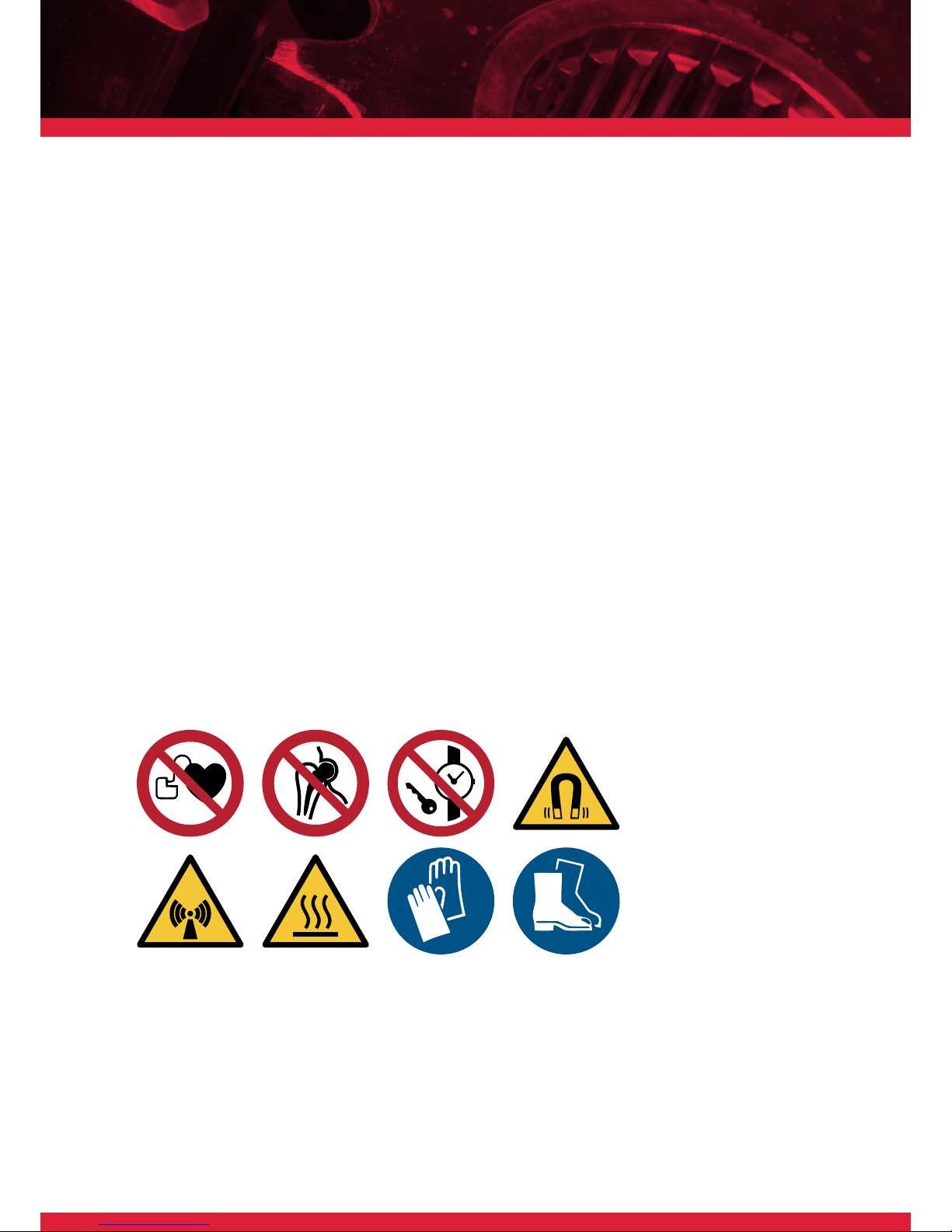
`Since a magnetic eld 4&5 is generated by the induction heater, people
wearing a pacemaker 1or other implant device 2should not work or
be in the immediate vicinity of the device. Other sensitive equipment
such as wrist watches, magnetic carriers, electronic circuits, etc. 3
might also be affected. The safety distance is 0.5 meters (19”).
`Use protective gloves as protection against burns to hands. The gloves
delivered are suitable for use up to temperatures of 150°C (302°F).
`Hot surface, avoid contact 6.
`Do not operate an induction heater in areas where there is risk of
explosion.
`Wear safety shoes 8.
1. 2. 3. 4.
8.7.
6.5.

TM INDUCTION HEATING
8
ST 2.0 |
`The user should have an appreciation of the contents of this user
manual, and be familiar with safe workshop practices.
`Follow the user manual at all times.
`Ensure that the induction heater operates at the correct supply
voltage. If the heater is not supplied with a plug, changes should only
be made by a suitably qualied electrician.
`Do not use or store the heater in humid environments. The heater is
designed for indoor use only.
` Use proper handling equipment, appropriate for the weight of the
workpiece and/or yoke. Never support components with a metal cable
or have any hanging in the proximity of the magnetic eld. Extremely
high currents can ow through the cable causing it to heat up quickly,
resulting in a risk of burning.
`Do not place any metal objects near the yokes and poles.
`Place heater on a stable, horizontal surface.
`Keep a minimum distance of 1 metre (38”) to surrounding objects.
`Use only in well ventilated areas.
`Do not heat objects containing oil, grease or similar substances.
Prevent possible generation of fumes and smoke.
`Do not inhale fumes or smoke from heated parts.
`Do not move or lift heater when warm after heating cycle.
`Do not touch the heater core during heating cycle.
SAFETY
INSTRUCTIONS

TM INDUCTION HEATING
9
ST 2.0 |
Should an error occur during the heating process, the induction heater will
automatically stop. The corresponding error will be displayed on screen.
In the case of user error, the display indicates what steps are to be taken
to correct the problem. More information about the types of errors can
be found in chapter 7 - ERRORS.
An induction heater produces an electromagnetic eld within a coil to
transfer energy to a workpiece. The table below shows values of the ux
density in microTesla (µT). These measurements can be used as a guide
conforming to local regulations regarding
the maximum time exposure to magnetic
elds. Different congurations may give
different values. It is impossible to provide
values for all combinations as the variety
of bearing types in combination with the
different yokes is large.
Total 50Hz RMS eld for magnetic measurement results. Max. magnetic
ux in safe exposure area, according to the German BG 11 Regulations
is 423 µ T.
SAFETY
FEATURES
MP1x 81 249 283
MP2x 16 34 74
MP3x 1 11 28
MP1y 156 181 185
MP2y 27 24 78
MP3y 9 9 41
Measurement position (cm) B-eldtotal (µT)
MP2x
60
MP1x
30
MP3x
90
30
60
90
MP1y
MP2y
MP3y
X
(cm)
Y
(cm)
TM INDUCTION HEATING
10
ST 2.0 |
INSTALLATION
3
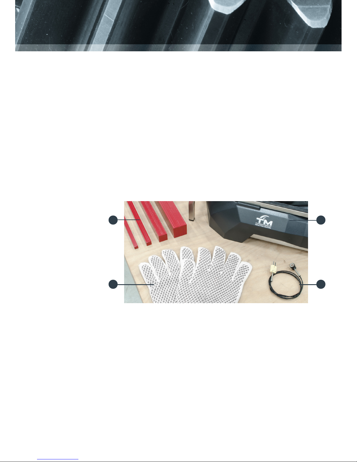
SCOPE OF
DELIVERY
Contents of the box
1. / /
2. Yoke(s)
3. Temperature probe(s)
4. Heat-resistant gloves
5. User Manual
6. Quickstart guide
1
4 3
2
Note
The comes with yokes 14, 25, and 40 included. The
yokes for and are all optional. The
heat-resistant gloves may differ from the picture above.
Follow the instructions specic for this heater on the supplied Quickstart
guide. If the Quickstart guide is not included in this box, please contact
your distributor or TM Induction Heating directly. The induction heater
must always be transported in the original box, thus also on return to the
manufacturer/distributor.
UNBOXING
TM INDUCTION HEATING
11
ST 2.0 |
Insert the plug into a shockproof wall socket
and then connect the heater to mains
electricity.
Turn main switch from 0 to 1. The heater
will emit a short beep and the touchscreen
displays the main menu. The induction heater
is now ready for use.
INSTALLATION
PROCESS
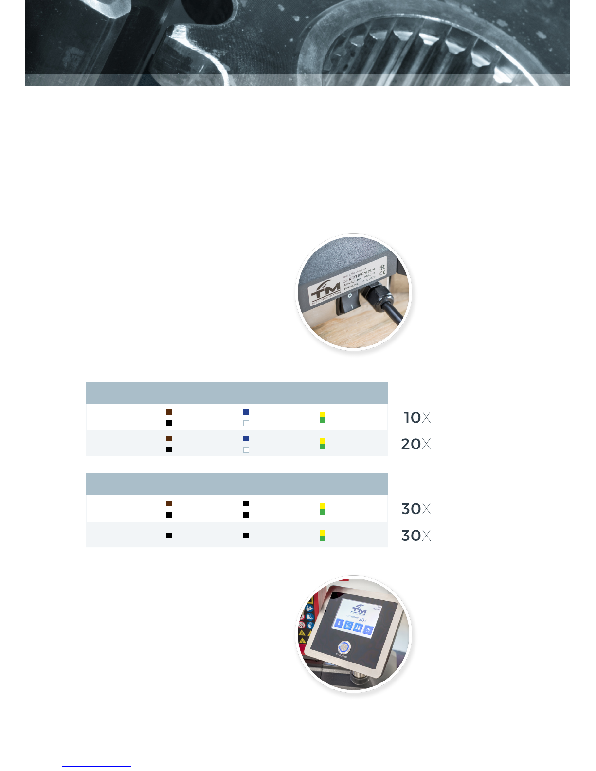
Ensure that supply voltage and current meet the specications. These can
be found on the type plate at the back of the
induction heater.
Each induction heater is provided with a plug,
but there are a large number of plug types.
Should the plug not t your power supply, a
suitable plug must be afxed by a qualied
electrician. Voltages may differ for customized
heaters.
Phase Neutral Ground
Voltage
110-230V Green/Yellow
Blue
White (USA)
Brown
Black (USA)
110-230V Green/Yellow
Blue
White (USA)
Brown
Black (USA)
Phase X / L1 Phase Y / L2 Ground
Voltage
460-575V Green/Yellow
Black Black
400-440V Green/Yellow
Brown
Black
Black
Black
TM INDUCTION HEATING
12
ST 2.0 |
SETTING UP THE WORKPIECE
4
`Use appropriate hoisting equipment for heavy components and yokes.
Manual lifting of heavy objects is a common cause of injury.
`Wear safety shoes during these procedures.
`The weight of the work-piece should not exceed the maximum weight
as shown in chapter 8 - WORKPIECE DIMENSIONS. Exceeding these
limits may result in catastrophic equipment failure and may also lead
to personal injury.
`Ensure there is no contact between the mains cable and the workpiece.
Damage to the cable may result in electrocution.
`Never support components with a metal cable and avoid metal cables
hanging in the proximity of the magnetic eld. Extremely high currents
can ow through the cable causing it to heat quickly, resulting in risk
of burning.
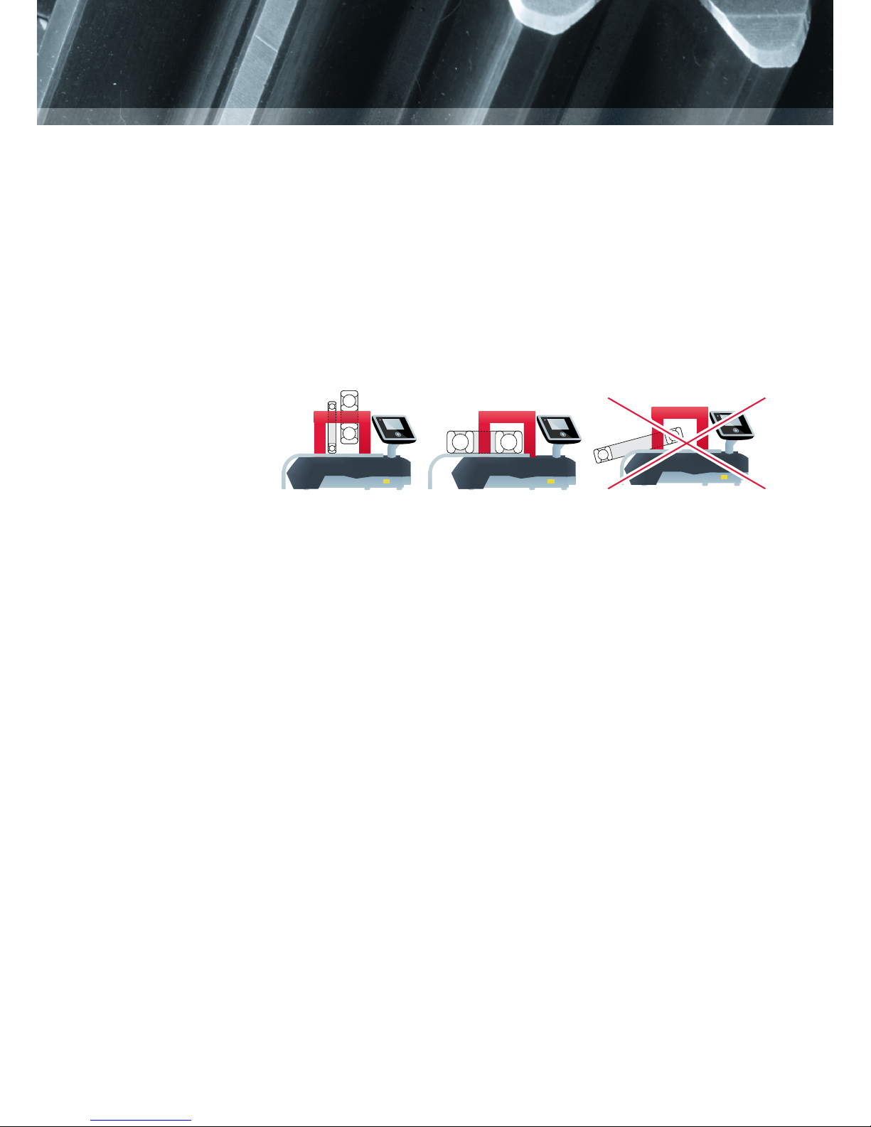
The workpiece can be set up in two different ways and must never touch
the housing. Small objects are to be heated in a vertical position.
VERTICAL HORIZONTAL
TM INDUCTION HEATING
13
ST 2.0 |
`Choose largest possible yoke which ts the diameter of the workpiece.
Position the workpiece onto the yoke and place the yoke with the
machine milled surface on the poles of the heater core.
`Always make sure that the workpiece avoids direct contact with the
housing of the heater.
`When a heating cycle is completed, always wear heat-resistant gloves.
The maximum temperature of the workpiece on a standard induction
heater is 240°C (464°F).
`Always treat yokes carefully. Falling, bumping, etc. can damage the
yoke and/or cause personal injury. Always store the yoke safely
immediately after use.
CHOOSING
THE YOKE

TM INDUCTION HEATING
14
ST 2.0 |
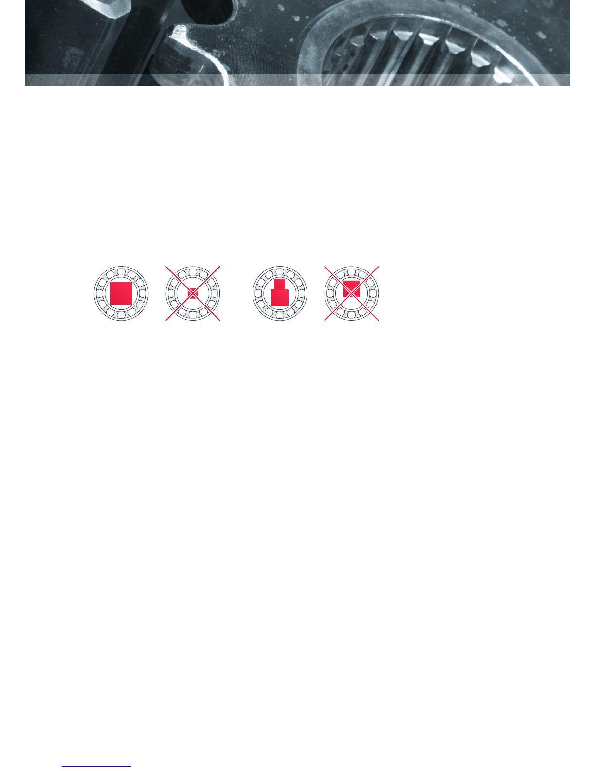
`Always use the magnetic temperature probe (hereafter referred to as
the ‘probe’) for heating in Temperature Mode or Ramp Mode.
`Place the probe on the workpiece, close to the bore. Make sure that
the surface used for the probe is free of grease and/or oil.
`If the induction heater has two probes: place one close to the bore
and the other on the outer ring.
`Our standard probes are suitable for operation up to a maximum
temperature of 240°C (464°F). The connection between magnet and
probe will break above the maximum temperature. If this occurs
when operating in Temperature Mode, the heater will turn itself off as
the probe will fail to register any increase
in the temperature over a set period of
time. Probes for higher temperatures are
optional.
`Connect the probe by inserting the plug
into the socket at the front of the heater,
with the red dot facing upwards.
POSITIONING
THE MAGNETIC
TEMPERATURE
PROBE(S)
Treat the probe with care. It is a valuable part of the heater and can easily
be damaged through careless handling. After use, we suggest that it be
placed on the side of the vertical pole.
CAUTION

TM INDUCTION HEATING
15
ST 2.0 |
When the induction heater is turned on, the homescreen can show up
to four buttons with different modes; Time Mode is always available.
Temperature Mode (with 1 sensor) and Ramp Mode will be enabled when
one sensor is inserted. An extra Temperature Mode (with 2 sensors) will
be enabled when a second sensor is inserted.
The start/stop button is used for starting heating cycles in one of the
modes, or to stop a heating cycle at any time.
When a heating cycle is complete, or stopped prematurely, the program
will return to the main screen of the heating mode. A graph can be
requested with the graph button .
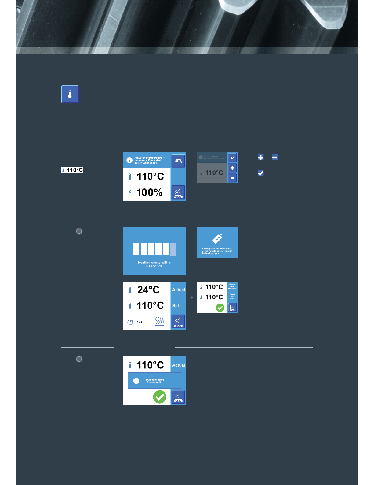
Every mode has three stages:
1. Preparation - The user can change the temperature and/or time.
2. Heating process - The induction heater starts the heating cycle.
3. Completion - The heating cycle has ended.
OPERATION 5
TM INDUCTION HEATING
16
ST 2.0 |
Press to start
the heating cycle
and stand at a safe
distance.
There is a 5 second
countdown before the
cycle starts.
When the preset
temperature has
been reached the
heater will hold that
temperature.
Press to stop the
heating cycle.
The induction heater
will now demagnetize.
Hereafter it will return
to the rst screen.
Alternatively, to start the
heating process, press
the start button on the
remote.
1. PREPARATION
2. HEATING PROCESS
3. COMPLETION
Press or to change the
temperature (max. 240°C).
To change the
temperature press
. Otherwise
proceed to step 2. Press when the
temperature is set.
TEMPERATURE MODE, ONE SENSOR
TM INDUCTION HEATING
17
ST 2.0 |
Press to start the
heating cycle and
stand at a safe
distance.
There is a 5 second
countdown before the
cycle starts.
When the preset
temperature has
been reached the
heater will hold that
temperature.
Press to stop the
heating cycle.
The induction heater
will now demagnetize.
Hereafter it will return
to the rst screen.
Alternatively, to start the
heating process, press
the start button on the
remote.
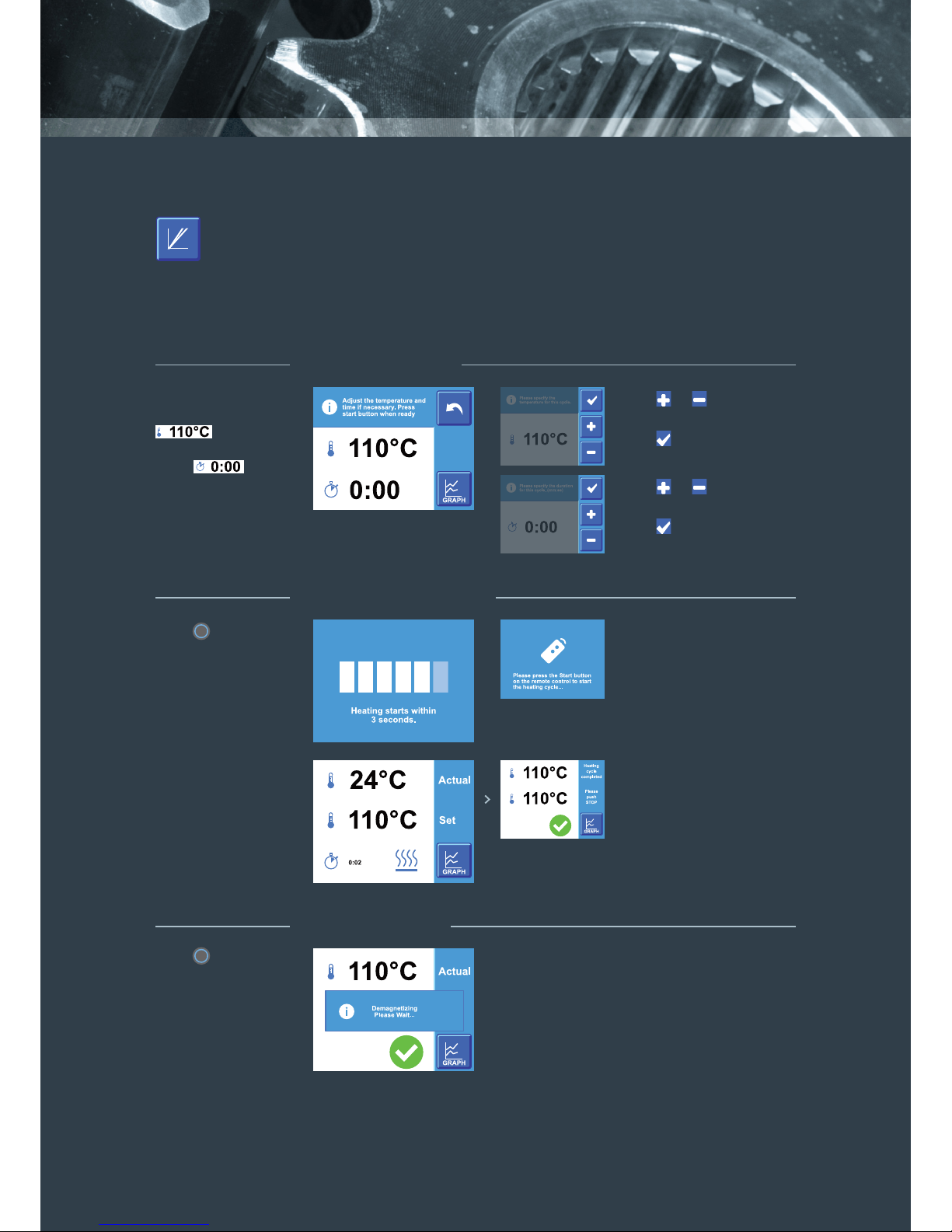
1. PREPARATION
2. HEATING PROCESS
3. COMPLETION
Press or to change the
temperature (max. 240°C).
Press or to
change the time.
To change the
temperature press
, to change
the heating time
press .
Otherwise proceed
to step 2.
Press when the
temperature is set.
Press when the time is
set.
35
RAMP MODE
TM INDUCTION HEATING
18
ST 2.0 |
Press to start
the heating cycle
and stand at a safe
distance.
There is a 5 second
countdown before the
cycle starts.
When the preset
temperature has
been reached the
heater will hold that
temperature.
Press to stop the
heating cycle.
The induction heater
will now demagnetize.
Hereafter it will return
to the rst screen.
Alternatively, to start the
heating process, press
the start button on the
remote.
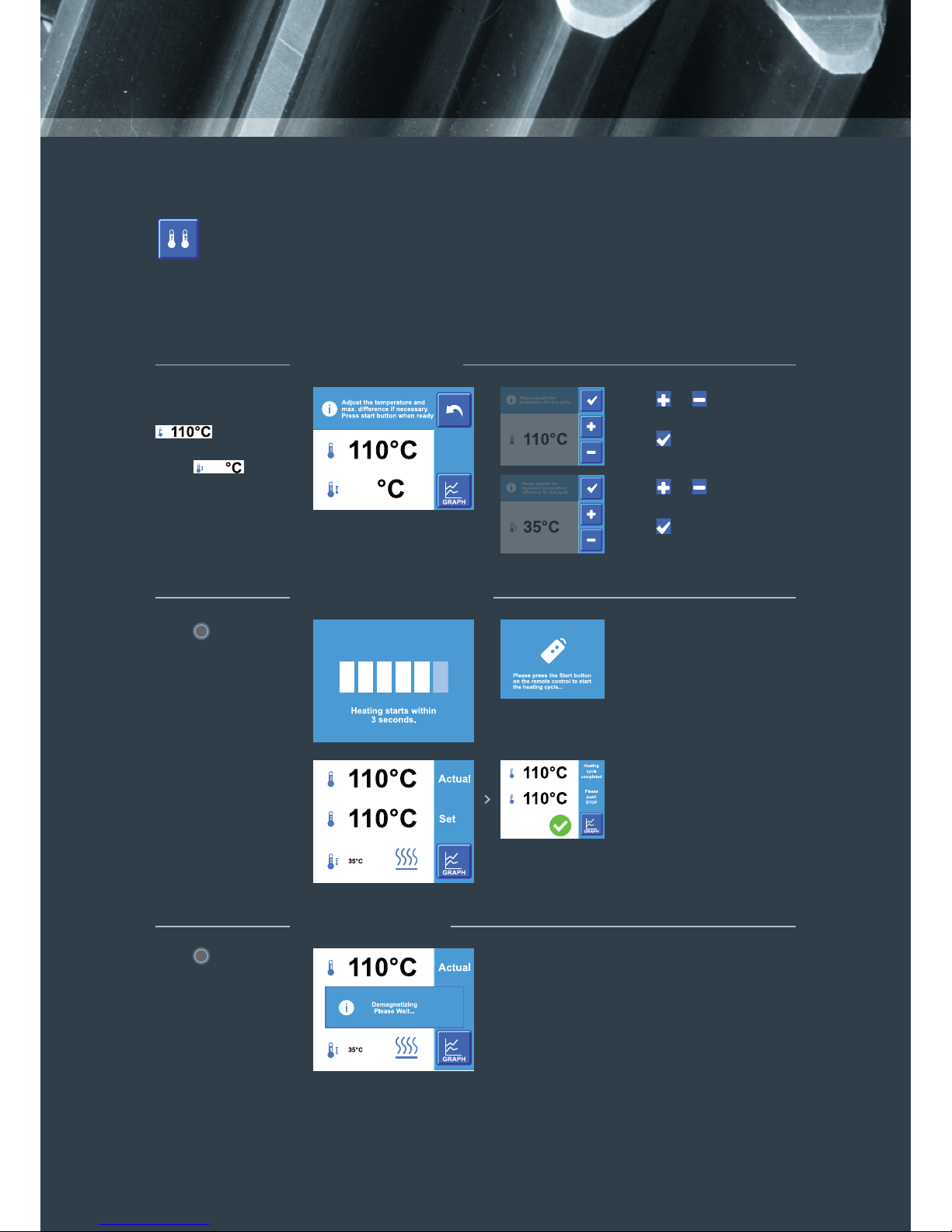
1. PREPARATION
2. HEATING PROCESS
3. COMPLETION
Press or to change the
temperature (max. 240°C).
Press or to change
the Δtemperature.
To change the
temperature press
, to change
the Δ temperature
press .
Otherwise proceed
to step 2.
Press when the
temperature is set.
Press when the
temperature is set.
35
35
35
35
TEMPERATURE MODE, TWO SENSORS
TM INDUCTION HEATING
19
ST 2.0 |
Press to start
the heating cycle
and stand at a safe
distance.
There is a 5 second
countdown before the
cycle starts.
Press to stop the
heating cycle.
The induction heater
will now demagnetize.
Hereafter it will return
to the rst screen.
Alternatively, to start the
heating process, press
the start button on the
remote.
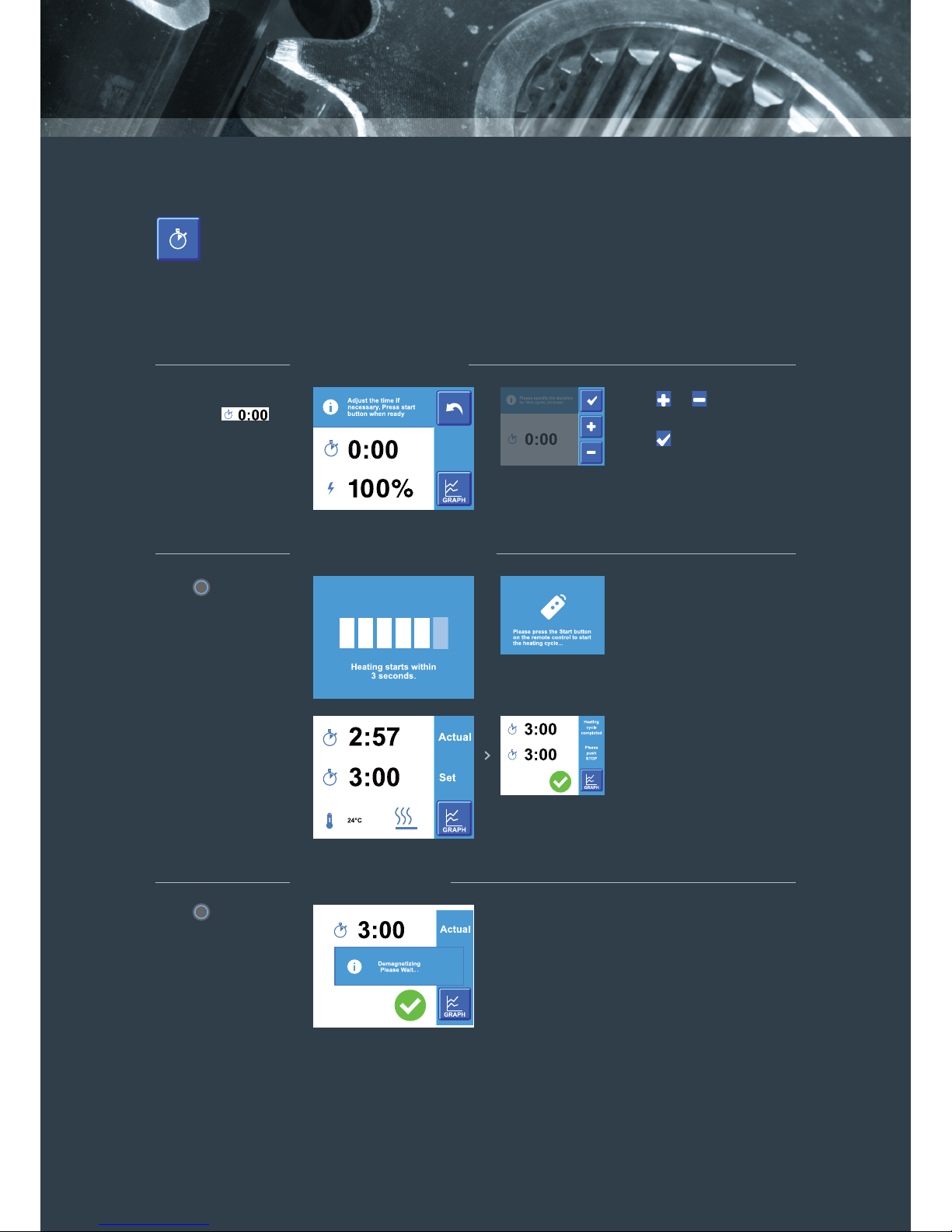
TIME MODE
1. PREPARATION
2. HEATING PROCESS
3. COMPLETION
Press or to change
the time (max. 99:59).
To change the heating
time press
Otherwise proceed to
step 2. Press when the time
is set.

TM INDUCTION HEATING
20
ST 2.0 |
USER MENU The user menu can be accessed by pressing the start/stop button for 8
seconds. Within this menu the user can view and/or change the following
settings:
Calibration Sensor 1
The temperature of sensor 1 can be
set if it is calibrated incorrectly.
Calibration Sensor 2
The temperature of sensor 2 can be
set if it is calibrated incorrectly.
Start Delay (5)
A delay can be set for the start of the
heating process. When the user starts
the heating process there will be a
delay so to enable removal to a safe
distance. The factory set delay is 5
seconds.
View Temp. Logging
The temperature log from the previous
heating cycle can be viewed here.
Screensaver (Off)
The settings for the screen saver can
be set here, ranging from off to a
certain number of seconds.
Time (HH:MM)
The current time can be set here.
This information will be used when
datalogging the heating cycle.
Date (DD/MM)
The current date can be set here.
This information will be used when
datalogging the heating cycle.
Year (YYYY)
The current year can be set here.
This information will be used when
datalogging the heating cycle.
Temp. Hold Hysteresis (3°C)
The max. temperature difference
before the heater starts heating again
can be set here.
Auto Sensor Select (On)
When this setting is turned on the
heater can recognize the difference
between Sensor 1 and Sensor 2 and
assign the order automatically.
Time Range (MM:SS)
The Time Range can be switched
between MM:SS (minutes and
seconds) and HH:MM (hours and
minutes). This Time Range setting
will be applied to the available range
when using Time Mode.
Exit (Discard Changes)
Any recent adjustments will
be discarded and the user returns to
the homescreen.
Update Firmware GUI
When a USB drive (containing an
update for the User Interface) is
inserted this option will show. Press
and follow the on-screen instructions
to update the heater.
Update Firmware PWR
When a USB drive (containing
an update for the Powerboard) is
inserted this option will show. Press
and follow the on-screen instructions
to update the heater.
Update Languages
When a USB drive (containing an
update for texts) is inserted this
option will show. Press and follow the
on-screen instructions to update the
Fonts and Texts.
Cur. Version GUI
The current version of the User
Interface is shown here.
Cur. Version PWR
The current version of the
Powerboard is shown here.
Number of Cycles
The Number of Cycles shows the
amount of heating cycles for the
induction heater.
Heating Timer
The Service Counter shows the
total time (all heating cycles added
together) for the induction heater.
Reset to Factory Settings
Each user setting will be reset
to its original factory values.
Languages
The languages of the heater can be
changed to English, Spanish, German,
and French. More languages can be
added later.
Default Temperature (110°C)
The default temperature can be set.
The factory set temperature
is 110°C (230°F).
Temp. Hold (On)
Temperature hold can be turned on or
off. During pendulation the heater will
heat to the set temperature and cools
down by 3°C, then heats again to the
set temperature, etc.
Temp. Hold Duration (5:00)
The duration of the temperature
hold can be set. With the factory
set duration of 5:00 min the heater
pendulates indenitely.
Completion Signal (On)
The buzzer can be turned on or off.
When on the heater will buzz when
it reaches the set temperature. The
factory set value is ‘on’.
Temperature Unit (°C)
The temperature unit can be changed
to Celsius or Fahrenheit. The factory
set temperature unit is Celsius,
Fahrenheit in the USA.
Maximum Temp. Delta (35°C)
The max. temperature difference
between the two sensors can be set.
The factory set temperature difference
is 35°C (122°F).
Remote Control (On)
The remote control function can be
turned on or off. This setting is shown
only when the remote has been
included.
U0
U1
U2
U3
U4
U5
U6
U7
U8
U9
U10
U12
U13
U14
U15
U16
U17
U19
U20
U22
U24
U26
U27
U28
U29
U30
U31
U32
This manual suits for next models
2
Table of contents
Other TM Induction Heating Heater manuals

Popular Heater manuals by other brands

MCS
MCS BV 170E User and Maintenance Book

Inverter Fusion
Inverter Fusion RAV-SM2000DH FS Installation and owner's manual

Jevi
Jevi 3000T Installation instruction

Chromalpx
Chromalpx PF474-2 Installation, operation and maintenance

Nibe
Nibe ELK 15 Installation and maintenance instructions

MILL
MILL Gentle Air Series Assembly and instruction manual


