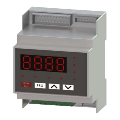
TMCON FT803 User manual

Economical Smart Temperature Controller
1 2 3
4 Wiring diagram、
4
21
Operating Ambient Temperature:0~60°C;Humidity≤90%RH
Response time ≤0.5Sec(when digital filter parameter InF=0)
Relay output
SSR Voltage output
TRIAC no contact discrete output
3A/250VAC 5A/30VDC
0.2A (continuous), 2A (20mS instantaneous, repeat period≥5s) /100~240VAC
12VDC/50mA(Used to drive SSR)
Electromagnetic compatibility (EMC) IEC61000-4-4(Electrical Fast Transient Burst)±4KV/5KHz;IEC61000-4-5(Surge),4KV
R
FT803
1、main features
2、Model defined
FT803
AC/DC100 240V , or AC/DC12-24V(~-15%, +10%/50-60HZ)
0.3% FS ± 1 measurement unit
48X48mm 72X72mm 96X96mm 48X96mm 96X48mm
45 X45
+0.6 +0.668 X68
+0.6 +0.692 X92
+0.6 +0.6
Measurement accuracy
Panel size(W*H)
Panel cutout size
3、Technical parameters
size code G D A E F
Output mode
Power consumption Approx. 5.2 VA at 100 to 240 VAC, Approx. 3 VA at 12 to 24 VDC
Operation Manual
Gross weight Approx. 177 g Approx. 272 g Approx. 419 g Approx. 286 g
FT803,The temperature controller belongs to the economy,The operation is simple, easy to
learn and use.
Use digital calibration technology for input Measurement accuracy:0.3%FS,Support
standard thermocouples and platinum resistance,maximum resolution is 0.1℃.
Use advanced artificial intelligent control algorithm, no overshoot and with the function of
auto tuning (AT) and self-adaptation.
With worldwide power supply of AC/DC100-240V or AC/DC12-24V and various installation
dimensions for users to choose.
Power supply voltage
5
45 X92
+0.6 +0.692 X45
+0.6+0.6
Relay contacts output
Code OUT(Master output)
R
QSSR voltage output
W1 TRIAC no contact
normally open output
W2 TRIAC no contact
normally closed output
NNone
2
48X48mm
Code Panel size(W*H)
G
D72X72mm
A96X96mm
E
F
48X96mm
96X48mm
1
Light gray
Code Shell color
Black
B
None
4
AC/DC100~240V
Code Power
AC/DC12-24V
D
None
5
None
Code ALM Alarm)(
1 relay contact output
1
N
3
22 relay contact output
Panel back depth 86mm
89mm
99mm 99mm
72mm
K(-50~+1300°C),E(0~800°C),J(0~1000°C),N(0~1300°C),
Pt100(-200~+600°C)
0、0.0
Decimal point
Input type and
Measuring range
+
ABB
-
12
10
9
8
76
11
12
13
345
AL1
-
+
OUT
COM
N/O
AL2
+
AB
-
12
109
8
3
B
14
13
12
11
18
4567
COM
-
+
OUT
AL1 AL2
N/O
N/OCOM N/C
POWER
COM
N/CN/O
COM N/OCOM N/O
POWER
15
16
17
+
A
B
B
-
OUT
-+
AL2
1
2
9
8
3
4
5
6
7
13
12
11
10
14
15
16
17
18
+
A
B
B
-
1
2
14
13
12
11
8
3
4
5
6
7
15
16
OUT
AL2
+
AL1
-
9
10
POWER
COM
N/ON/C
N/O
COM
N/C
N/O
COM
POWER
AL1
COM N/C
N/ON/OCOM
COM N/O
N/C
Wiring graph for G(48X48mm) size Wiring graph for G(72X72mm) size
Wiring graph for G(96X96mm) size Wiring graph for
E(48X96mm) ,F(96X48mm) size

5.Panel Description
Upper display window
1
Lower display window
2
To the parameter key, the Enter key
3
Data shift key
4
Increase keythe
5
Reduce the key
6
OUT Lamp
7
6、Display the status and basic operation
7、Parameter list and function
press and hold key 2 seconds, LOC parameter appears, set the LOC = 800,Then press
the key to confirm and enter the system parameter setting state.
Parameter
code
Meaning of
parameters Explain Setting
range
LOC Parameter
lock
LOC<9000, will automatically for 0, allowed to modify the SV Set
Value.
LOC≥9000, are not allowed to modify the SV Set Value.
Set the LOC = 800, then press key to confirm, can enter the
following system parameters.
0~9999
3 4
OUT
AUT
A L 1
TF800
TMCON
PV
SV
A L 2
1
2
3
46
7
8
5
PV
SV
Press 2 SEC
+
The next
parameter
2 SEC,Return to the
previous parameter
For example:
measuring a value of 600.0
Set value 600.5
The basic display state
6.1.System parameter setting
PV
SV
LOC parameter
appears,
Set the LOC = 800,
Then Press
Instrument power
Access to the system parameter setting state
In the basic display state, press and hold key 2 seconds, LOC parameter appears, set the
LOC = 800,Then press the button to confirm and enter the system parameter setting state.
, , Key can directly modify the parameter values. Press the key to reducing
the data, press the to increase the data,Waiting to modify the value of the decimal
point will flash (like a cursor).press key and hold, you can quickly increase / decrease in value,
And the speed will be automatically accelerated. also press the key to move to modify the
data location (cursor), the operation is more efficient. Key can be stored to modify
parameter values and display the next parameter,press and hold key 2 seconds,and can
return to the previous parameter; and hold key and then press the key can
immediately exit the parameter setting state.
key
press
6.2 Set Value Setting
In basal display status, if the parameter lock “Loc” isn't locked, we can set setpoint (SV) by
pressing first、then can press , or to adjust value. Press key to decrease
the value, key to increase the value, and key to move to the digit expected to modify.
Keep pressing or , the speed of decreasing or inscreasing value get quick. The range
of setpoint is between the parameter SPL and SPH.
6.3 “At”PID Parameter auto-tuning
"At" parameter "OFF" is set to "ON" and then press the KEy to confirm instrument can start
the implementation of the auto-tuning Given function,the instrument in the basic display state
display will flash the word "At", the instrument after 2 oscillation cycle ON-OFF control can
automatically calculate the PID parameters.If you want to advance to give up auto-tuning , "At"
parameter “ON” is set to “OFF” and then press key to confirm.
Given tuning parameter values obtained are not identical, to perform auto-tuning function,
9
AL1 Lamp
8
AL2 Lamp
9
should be first given value set in The most commonly used value or middle value, if the system
is good insulation properties of the furnace, the given value should be set in the system uses
the maximum, and then Execute the start of the operation of auto-tuning function. Reasons to
learn, auto-tuning after the initial use, the effect may not be the best, you need a period of time
(usually the same time auto-tuning control) before they can get the best results.
AL1 high
limit alarm
value
AL1 low
limit alarm
value
-999~
+32000
“HAL1” is the absolute value alarm or deviation value alarm, by
“ALtd” parameter definition.
When the value set to Max. will disable this function.(3200)
“LAL1” is the absolute value alarm or deviation value alarm, by
“ALtd” parameter definition.
When the value set to Min. will disable this function.(-999)
AL2 high
limit alarm
value
AL2 low
limit alarm
value
“HAL1” is the absolute value alarm or deviation value alarm, by
“ALtd” parameter definition.
When the value set to Max. will disable this function.(3200)
“LAL1” is the absolute value alarm or deviation value alarm, by
“ALtd” parameter definition.
When the value set to Min. will disable this function.(-999)
HAL2
LAL2
HAL1
LAL1
Alarm
hysteresis
Alarm mode
Avoid frequent alarm on-off action because of the fluctuation of PV
ALtd=0,AL1is the is the
.
deviation value alarm,AL2 absolute
value alarm
ALtd=1,AL1 and AL2 is the absolute value alarm.
ALtd=2,AL1 and AL2 is the deviation value alarm.
Control
mode
onoF: on-off control. For situation not requiring high precision.
FPId: advanced artificial intelligence ”FUZZY PID“ control.
0~2000
0~2
OFF: close the function.
ON: start a function.
finish will automatically returns to the OFF state.
auto-tuning
auto-tuning
auto-tuning
auto-tuning ON
OFF
onoF
FPId
onr: Reverse acting. Increase in measured variable causes a
decrease in the output, such as heating control.
ond: Direct acting. Increase in measured variable causes an
increase in the output, such as refrigerating control.
Selection of
heating
refrigeration
AHYS
ALtd
CntL
At
orEv onr
ond
Proportional
band
Integration
time
No integral effect when I=0
1~32000
1~9999
seconds
Proportional band in PID and APID control. Instead of percentage
of the measurement range, the unit is the same as PV.
Generally, optimal P, I, D and CP can obtained by auto tuning. They
can also be manually inputted if you already know the correct
values.
P
I

6
8、Note
!
Read this manual before using, to prevent the error operation
caused by the failure to Fully understand the operating
procedures, and retain the manual for ready reference.
( )
( )
1 Can not normally display measured values in the display window alternating show:
"orAL" character, indicating that the input of the measurement signal abnormalities or Out of
range; check Int parameter settings, and then the input sensor signals are the same category,
if it is determined the same, check the input sensing Signal not pick the wrong line, if it is
determined to not pick the wrong line, check whether the sensor problem, replace another
sensor to try.
2 The instrument used by the local environmental temperature and humidity can not
exceed the scope of the provisions, the instrument around should allow sufficient space for
CP Control cycle CP reflect the instrument operator to adjust the speed, the size of
the CP that affect the control accuracy.
With SSR, SCR output control cycle preferable to shorter, usually
0.5-3.0 Seconds. The relay switch output is generally in 15-40
seconds.
When the output relay switches , the CP will be limited to
3 seconds, And self-tuning At will automatically set the CP as the
appropriate value, taking into account the control accuracy And
mechanical switch life.
When the control mode CntL = onoF, the action of the CP as an
output disconnect or power-on output ON Delay time.
0.2~
300.0
Int Input Signal Input spec:
K、E、J、N、Pt(Pt100)
dp Decimal
point
0 (no decimal), 0.0 (one decimal place).
InF
dU
SvL
SvH
-9990~
+30000
SC Input Shift
Adjustment
Sc is used to shift input to compensate the error caused by
transducer, input signal, or auto cold junction compensation of
thermocouple.
PV after compensation=PV before compensation + Sc It is generally
set to 0. The incorrect setting will cause measurement inaccurate.
-1999~
+4000
PV
input filter
The value of InF will determine the ability of filtering noise.
When a large value is set, the measurement input is stabilized but
the response speed is slow. Generally, it can be set to 1 to 3.
If great interference exists, then you can increase parameter “InF”
gradually to make momentary fluctuation of measured value less
than 2 to 5.
When the instrument is being metrological verified, “InF” s can be
set to 0 or 1 to shorten the response time.
Temperature
unit selection
°C:
°F:fahenheit equals
celsius equals
Low limit
of SV
Minimum value that SV is allowed to be.
Upper limit
of SV
Maximum value that SV is allowed to be.
0~40
°C
°F
HYS Control
hysteresis
0~2000
HYS is used for on-off control to avoid frequent on-off action of relay.
For a reverse acting (heating) system, when PV > SV, output turns
off; when PV<SV-HYS, output turns on.
For a direct acting (cooling) system, when PV<SV, output turns off;
when PV>SV+HYS, output turns on.
Differential
time
No derivative effect when d=0 0~3200
seconds
dheat dissipation, instrument internal temperature rise due to thermal radiation will lead to a
result of the measurement accuracy and service life of the affected. In this Case, to be taken
to a forced cooling fan or other measures to reduce the ambient temperature.
3 the extension or connection then the thermocouple leads should be used with the
thermocouple type to match the compensation conductor; extend or connect the
thermoelectric Resistance of the lead, you should use the minimal resistance of the wire and
cable away from power lines and load connection, in order to avoid signal interference.
( )
5
Guangzhou Tmcon Electronic Technology Co., Ltd.
R
Sales Hotline: -020 34273933 Technical Hotline:020-34273900
Http://www.china-tmcon.com E-mail:chinatmcon@163.com
Made in Guangzhou, China
0
0.0
Parameter code
*
* solid state relay output type factory is set to ,
the relay contact output type factory set to .
factory setting Parameter code Parameter code
factory setting factory setting
9、default settings.
Popular Controllers manuals by other brands
Kenwood
Kenwood KCA-R10 instruction manual
Murphy
Murphy EMS547 Specifications

Voicebird
Voicebird Voicebird Mini user guide
Becker
Becker Centronic UnitControl UC52 Assembly and operating instructions
Watersports Innovations
Watersports Innovations The Boost Box WS 1107 Installation & operation instructions
UCS
UCS QUASAR AC user manual
