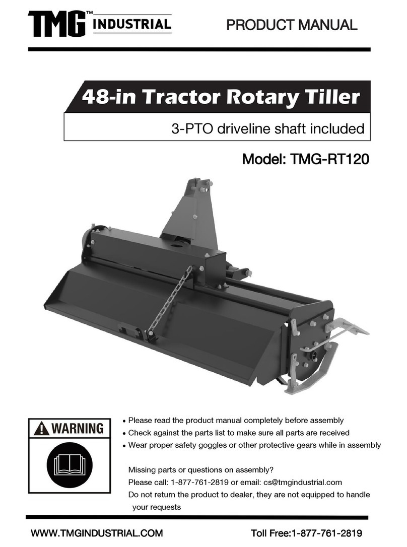
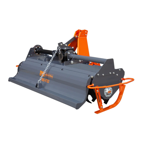
TMG TMG-RT165 User manual

WWW.TMGINDUSTRIAL.COM
Toll Free:1-877-761-2819
PRODUCT MANUAL
v.2022.03.31
3-Point Rotary Tiller
MODEL TMG-RT165/RT185

WWW.TMGINDUSTRIAL.COM
1 / 22
Toll Free:1-877-761-2819
Important Safety Information . . . . . . . . . . . . . . . . . . . . . . . . . . . . . . . . . . . . . . . . . . . . . 2
Safety at All Times . . . . . . . . . . . . . . . . . . . . . . . . . . . . . . . . . . . . . . . . . . . . . . . . . . . . . . . . . . . . . . . . . . . 2
Look For The Safety Alert Symbol . . . . . . . . . . . . . . . . . . . . . . . . . . . . . . . . . . . . . . . . . . . . . . . . . . . . . . . .2
Safety Labels . . . . . . . . . . . . . . . . . . . . . . . . . . . . . . . . . . . . . . . . . . . . . . . . . . . . . . . . . . . . . . . . . . . . . . . .5
Introduction . . . . . . . . . . . . . . . . . . . . . . . . . . . . . . . . . . . . . . . . . . . . . . . . . . . . . . . . . . .7
Application . . . . . . . . . . . . . . . . . . . . . . . . . . . . . . . . . . . . . . . . . . . . . . . . . . . . . . . . . . . . . . . . . . . . . . . . . 7
Terminology . . . . . . . . . . . . . . . . . . . . . . . . . . . . . . . . . . . . . . . . . . . . . . . . . . . . . . . . . . . . . . . . . . . . . . . . .. .7
Owner Assistance . . . . . . . . . . . . . . . . . . . . . . . . . . . . . . . . . . . . . . . . . . . . . . . . . . . . . . . . . . . . . . . . . . 7
Serial Number Plate . . . . . . . . . . . . . . . . . . . . . . . . . . . . . . . . . . . . . . . . . . . . . . . . . . . . . . . . . . . . . . . . 7
Section 1: Assembly and Set-up . . . . . . . . . . . . . . . . . . . . . . . . . . . . . . . . . . . . . . . . . . . 8
Tractor Requirements . . . . . . . . . . . . . . . . . . . . . . . . . . . . . . . . . . . . . . . . . . . . . . . . . . . . . . . . . . .. . . .8
Assembly. . . . . . . . . . . . . . . . . . . . . . . . . . . . . . . . . . . . . . . . . . . . . . . . . . . . . . . . . . . . . . . . . . . . . .. . .8
Tractor Hook-Up . . . . . . . . . . . . . . . . . . . . . . . . . . . . . . . . . . . . . . . . . . . . . . . . . . . . . . . . . . . . . . . . . . . . . 9
Driveline Hook-Up . . . . . . . . . . . . . . . . . . . . . . . . . . . . . . . . . . . . . . . . . . . . . . . . . . . . . . . . . . . . . . . . . . 9
Section 2: Operating Instructions . . . . . . . . . . . . . . . . . . . . . . . . . . . . . . . . . . . . . . . . . 9
Safety Information. . . . . . . . . . . . . . . . . . . . . . . . . . . . . . . . . . . . . . . . . . . . . . . . . . . . . . . . . . . . . . . . . . . . 9
General Operating Notes . . . . . . . . . . . . . . . . . . . . . . . . . . . . . . . . . . . . . . . . . . . . . . . . .. . . . . . . . . . . . . 11
General Operating Instructions . . . . . . . . . . . . . . . . . . . . . . . . . . . . . . . . . . . . . . . . . . . . . . . . . . . . . . . . . 11
Skid Shoe Adjustment. . . . . . . . . . . . . . . . . . . . . . . . . . . . . . . . . . . . . . . . . . . . . . . . . . . . . . . . . . . . . . . .11
Section 3: Maintenance and Lubrication . . . . . . . . . . . . . . . . . . . . . . . . . . . . . . . . . . . . . 12
Maintenance . . . . . . . . . . . . . . . . . . . . . . . . . . . . . . . . . . . . . . . . . . . . . . . . . . . . . . . . . . . . . . . . . . . . . 12
Tine Replacement. . . . . . . . . . . . . . . . . . . . . . . . . . . . . . . . . . . . . . . . . . . . . . . . . . . . . . . . . . . . . . . . . . .11
Long-Term Storage. . . . . . . . . . . . . . . . . . . . . . . . . . . . . . . . . . . . . . . . . . . . . . . . . . . . . . . . . . . . . . . . . 12
Lubrication . . . . . . . . . . . . . . . . . . . . . . . . . . . . . . . . . . . . . . . . . . . . . . . . . . . . . . . . . . . . . . . . . . . . . . . . . . 13
Section 4: Troubleshooting . . . . . . . . . . . . . . . . . . . . . . . . . . . . . . . . . . . . . . . . . . . . . . . . . . 14
Section 5: Appendix . . . . . . . . . . . . . . . . . . . . . . . . . . . . . . . . . . . . . . . . . . . . . . . . . . . . . . . 15
Section 6: Part List . . . . . . . . . . . . . . . . . . . . . . . . . . . . . . . . . . . . . . . . . . . . . . . . . . . . . . 16

WWW.TMGINDUSTRIAL.COM
2 / 22
Toll Free:1-877-761-2819
Important Safety Information
Safety at All Times
Careful operation is your best assurance against an accident. All operators, no matter how much experience they may have,
should carefully read this manual and other related manuals, or have the manuals read to them, before operating the power
machine and this implement.
l Thoroughly read and understand the “Safety Label” section. Read all instructions noted on them.
l Do not operate the equipment while under the influence of drugs or alcohol as they impair the ability to safely and
properly operate the equipment.
l The operator should be familiar with all functions of the tractor and attached implement, and be able to handle
emergencies quickly.
l Make sure all guards and shields appropriate for the operation are in place and secured before operating the implement.
l Keep all bystanders away from equipment and work area.
l Start tractor from the driver’s seat with hydraulic controls in neutral.
l Operate tractor and controls from the driver’s seat only.
l Never dismount from a moving tractor or leave tractor unattended with engine running.
l Do not allow anyone to stand between tractor and implement while backing up to implement.
l Keep hands, feet, and clothing away from power-driven parts.
l While transporting and operating equipment, watch out for objects overhead and along side such as fences, trees,
buildings, wires, etc.
l Do not turn tractor so tight as to cause hitched implement to ride up on the tractor’s rear wheel.
l Store implement in a safe and secure area where children normally do not play. When needed, secure implement against
falling with support blocks.
Look for the Safety Alert Symbol
The SAFETY ALERT SYMBOL indicates there is a potential hazard to personal safety and extra precaution must be taken.
When you see this symbol, be alert and carefully read the message that follows it. Hazard control, and accident prevention are
dependent upon the awareness, concern, prudence, and proper training of personnel involved in the operation, transport,
maintenance, and storage of equipment.
Be Aware of Signal Words
A signal word designates a degree or level of hazard seriousness. They are:
DANGER: Indicates a hazardous situation that, if not avoided, will result in death or serious injury.
WARNING: Indicates a hazardous situation that, if not avoided, could result in death or serious injury.
CAUTION: Indicates a hazardous situation that, if not avoided, may result in minor or moderate injury.
Be Aware of Special Notices
Special notices are intended to point out important and helpful information that should be followed. They are usually placed
inside a box. They are:
IMPORTANT: Indicates that equipment or property damage could result if instructions are not followed.
NOTES: Indicates supplementary explanations that will be helpful when using the equipment.
Safety Precautions for Children
Tragedy can occur if the operator is not alert to the presence of children, Children generally are attracted to implements and
their work.
l Never assume children will remain where you last saw them.
l Keep children out of the work area and under the watchful eye of a responsible adult.
l Be alert and shut the implement and tractor down if children enter the work area.
l Never carry children on the tractor or implement. There is not a safe place for them to ride. They may fall off and be run

WWW.TMGINDUSTRIAL.COM
3 / 22
Toll Free:1-877-761-2819
over or interfere with the control of the power machine.
l Never allow children to operate the power machine, even under adult supervision.
l Never allow children to play on the power machine or implement.
l Use extra caution when backing up. Before the tractor starts to move, look down and behind to make sure the area is
clear.
Tractor Shutdown & Storage
l If engaged, disengage power take-off.
l Park on solid, level ground and lower implement to ground or onto support blocks.
l Put tractor in park or set park brake.
l Turn off engine and remove ignition key to prevent unauthorized starting.
l Relieve all hydraulic pressure to auxiliary hydraulic lines.
l Wait for all components to stop before leaving operator’s seat.
l Use steps, grab-handles and anti-slip surfaces when stepping on and off the tractor.
Listed below are common practices that may or may not be applicable to the products described in this manual.
Transport Safely
l Comply with federal, state, and local laws.
l Use towing vehicle and trailer of adequate size and capacity. Secure equipment towed on a trailer with tie downs and
chains.
l Sudden braking can cause a towed trailer to swerve unexpectedly. Reduce speed if towed trailer is not equipped with
brakes.
l Avoid contact with any overhead utility lines or electrically charged conductors.
l Always drive with load on end of loader arms low to the ground.
l Always drive straight up and down steep inclines with heavy end of skid steer on the “uphill” side.
l Engage park brake when stopped on an incline.
l Maximum transport speed for an attached equipment is 20 mph (32 km/h). DO NOT EXCEED. Never travel at a speed
which does not allow adequate control of steering and stopping. Some rough terrains require a slower speed.
l As a guideline, use the following maximum speed weight ratios for attached equipment:
20 mph (32 km/h) when weight of attached equipment is less than or equal to the weight of machine towing the equipment.
10 mph (16 km/h) when weight of attached equipment exceeds weight of machine towing equipment but not more than
double the weight.
l IMPORTANT: Do not tow a load that is more than double the weight of the vehicle towing the load.
Practice Safe Maintenance
l Understand procedure before doing work. Refer to the Operator’s Manual for additional information.
l Work on a level surface in a clean dry area that is well-lit.
l Lower implement to the ground and follow all shutdown procedures before leaving the operator’s seat to perform
maintenance.
l Do not work under any hydraulically supported equipment. It can settle, suddenly leak down, or be lowered accidentally.
If it is necessary to work under the equipment, securely support it with stands or suitable blocking beforehand.
l Use properly grounded electrical outlets and tools.
l Use correct tools and equipment for the job that are in good condition.
l Allow equipment to cool before working on it.
l Disconnect battery ground cable (-) before servicing or adjusting electrical systems or before welding on implement. s
Inspect all parts. Make certain parts are in good condition & installed properly.
l Replace parts on this implement with genuine Land Pride parts only. Do not alter this implement in a way which will

WWW.TMGINDUSTRIAL.COM
4 / 22
Toll Free:1-877-761-2819
adversely affect its performance.
l Do not grease or oil implement while it is in operation. sRemove buildup of grease, oil, or debris.
l Always make sure any material and waste products from the repair and maintenance of the implement are properly
collected and disposed.
l Remove all tools and unused parts from equipment before operation.
l Do not weld or torch on galvanized metal as it will release toxic fumes.
Prepare for Emergencies
l Be prepared if a fire starts.
l Keep a first aid kit and fire extinguisher handy.
l Keep emergency numbers for doctor, ambulance, hospital, and fire department near the phone.
Wear Personal Protective Equipment (PPE)
l Wear protective clothing and equipment appropriate for the job such as safety shoes, safety, glasses, hard hat, dust
mask, and ear plugs.
l Clothing should fit snug without fringes and pull strings to avoid entanglement with moving parts.
l Prolonged exposure to loud noise can cause hearing impairment or hearing loss. Wear suitable hearing protection such
as earmuffs or earplugs.
l Operating a machine safely requires the operator’s full attention. Avoid wearing headphones while operating equipment.
Avoid High Pressure Fluids
l Escaping fluid under pressure will penetrate the skin or eyes causing serious injury.
l Relieve all residual pressure before disconnecting hydraulic lines or performing work on the hydraulic system.
l Make sure all hydraulic fluid connections are properly tightened/torqued and all hydraulic hoses and lines are in good
condition before applying pressure to the system.
l Use a piece of paper or cardboard, NOT BODY PARTS, to check for suspected leaks.
l Wear protective gloves and safety glasses or goggles when working with hydraulic systems.
l DO NOT DELAY. If an accident occurs, seek immediate emergency medical care or gangrene may result.
Use Safety Lights and Devices
l A Slow moving power machine can create a hazard when driven on public roads. They are difficult to see, especially at
night. Use the Slow Moving Vehicle (SMV) sign when on public roads.
l Flashing warning lights and turn signals are recommended whenever driving on public roads.
Use Seat Belt and ROPS
l TMG recommends the use of a CAB or roll-over-protective-structures (ROPS) and seat belt in almost all power machines.
Combination of a CAB or ROPS and seat belt will reduce the risk of serious injury or death if the power machine should
be upset.
l If ROPS is in the locked-up position, fasten seat belt snugly and securely to help protect against serious injury or death
from falling and machine overturn.
Keep Riders Off Machinery
l Never carry riders on the tractor or implement.
l Riders obstruct operator’s view and interfere with the control of the power machine.
l Riders can be struck by objects or thrown from the equipment.
l Never use the tractor or implement to lift or transport riders.

WWW.TMGINDUSTRIAL.COM
5 / 22
Toll Free:1-877-761-2819
Avoid crystalline Silica (quartz) Dust
Because crystalline silica is a basic component of sand and granite, many activities at construction sites produce dust
containing crystalline silica. Trenching, sawing, and boring of material containing crystalline silica can produce dust
containing crystalline silica particles. This dust can cause serious injury to the lungs (silicosis).
There are guidelines which should be followed if crystalline silica (quartz) is present in the dust.
l Be aware of and follow OSHA (or other local, State, or Federal) guidelines for exposure to airborne crystalline silica.
l Know the work operations where exposure to crystalline silica may occur.
l Participate in air monitoring or training programs offered by the employer.
l Be aware of and use optional equipment controls such as water sprays, local exhaust ventilation, and enclosed cabs
with positive pressure air conditioning if the machine has such equipment. Otherwise respirators shall be worn.
l Where respirators are required, wear a respirator approved for protection against crystalline silica containing dust. Do
not alter respirator in any way. Workers who use tight-fitting respirators can not have beards/mustaches which interfere
with the respirator seal to the face.
l If possible, change into disposable or washable work clothes at the work site; shower and change into clean clothing
before leaving the work site.
l Do not eat, drink, use tobacco products, or apply cosmetics in areas where there is dust containing crystalline silica.
l Store food, drink, and personal belongings away from the work area.
l Wash hands and face before eating, drinking, smoking, or applying cosmetics after leaving the exposure area.
Handle Chemicals Properly
l Protective clothing should be worn.
l Handle all chemicals with care.
l Follow instructions on container label.
l Agricultural chemicals can be dangerous. Improper use can seriously injure persons, animals,
l plants, soil, and property.
l Inhaling smoke from any type of chemical fire can be a serious health hazard.
l Store or dispose of unused chemicals as specified by the chemical manufacturer.
Safety Labels
Your Rotary Tiller comes equipped with all safety labels in place. They were designed to help you safely operate your
equipment. Read and follow their directions.
1. Keep all safety labels clean and legible.
2. Refer to this section for proper label placement. Replace all damaged or missing labels.
3. Some new equipment installed during repair requires safety labels to be affixed to the replaced component as specified
by TMG. When ordering new components make sure the correct safety labels are included in the request.
4. Refer to this section for proper label placement. To install new labels:
a. Clean surface area where label is to be placed.
b. Spray soapy water onto the cleaned area.
c. Peel backing from label and press label firmly onto the surface.
d. Squeeze out air bubbles with edge of a credit card or with a similar type of straight edge.

WWW.TMGINDUSTRIAL.COM
6 / 22
Toll Free:1-877-761-2819

WWW.TMGINDUSTRIAL.COM
7 / 22
Toll Free:1-877-761-2819
Introduction
TMG welcomes you to the growing family of new product owners. This implement has been designed with care and built by
skilled workers using quality materials. Proper assembly, maintenance, and safeoperating practices will help you get years
of satisfactory use from the rotary tiller.
Application
The rotary tillers are designed and built to till soil for seedbed and planting preparation with uses in both rural and non-rural
applications such as gardening and landscaping. They are designed for 30-60hp tractors with Category I & II three point
hitch mounting, 540 rpm power take-off speed.
Terminology
“Right” or “Left” as used in this manual is determined by facing the direction the machine will operate while in use unless
otherwise stated.
Owner Assistance
The Warranty Registration card should be filled out by the dealer at the time of purchase. This information is necessary to
provide you with quality customer service. If customer service or repair parts are required contact a dealer. A dealer has
trained personnel, repair parts and equipment needed to service the machine. The parts on your machine have been
specially designed and should only be replaced with genuine parts.
Serial Number Plate
For prompt service always use the serial number and model number when ordering parts from your dealer. Be sure to include
your serial and model numbers in correspondence also.

WWW.TMGINDUSTRIAL.COM
8 / 22
Toll Free:1-877-761-2819
Section 1: Assembly and Set-up
Tractor Requirements
Tractor horsepower should be within the range noted below. Tractors outside the horsepower range must not be
used.
Hitch Category----------------3-Point Cat. I & II
Power Take-Off Speed-----------------540 rpm
Horsepower Requirements-----------30-60 hp
Assembly
1. Remove all loose parts or packaging from the crate, check goods without damaged and omission.
2. Check the packing list as below,
Part No.
Ref. No.
Parts Description
Qty
1
1GR185.01
Frame and Rotor Assembly
1
2
GB/T5872-2000
Bolt-M12x40
8
3
1GR185.01.013
Hitch
1
4
1G135.02.117
Guard shade
1
5
T5S-YS-07-07*750
PTO drive shaft
1
3. Assembly the part 4 (guard shade) to gearbox, assemble the part 3 (hitch) to the part 1(frame and rotor assembly), you
will get the rotary tiller assembled.

WWW.TMGINDUSTRIAL.COM
9 / 22
Toll Free:1-877-761-2819
Tractor Hook-Up
IMPORTANT: The tractor’s lower 3-point arms must be stabilized to prevent side-to-side movement. Most tractors have sway
blocks or adjustable chains for this purpose.
IMPORTANT: To prevent damaging the park stand, always store the stand in its transport position before moving the tiller.
1. Make sure you have read and follow all safety alerts, Important Notes, and Notes before continuing.
2. The tiller is equipped with a Cat. l & II hitch. Make sure your tractor’s hitch is compatible with the tiller’s hitch.
3. Remove lower linchpins and hitch pins .
4. Customer to supply upper hitch pin and hitch pin keeper. If installed, remove customer supplied hitch pin and hitch pin
keeper.
5. Slowly back tractor to tiller while using tractor’s 3-point control lever to align holes in lower 3-point lift arms with holes in
clevises.
6. Put tractor gear selector in park or set park brake, shut off tractor engine, and remove switch key before dismounting
tractor.
7. Attach lower 3-point lift arms to clevises with hitch pins. Secure hitch pins with linchpins.
8. Attach tractor’s top center 3-point link to tiller hitch plates with customer supplied hitch pin and hitch pin keeper.
9. With gear selector in park or tractor park brake set, start tractor and raise tiller off the ground several inches. Shut
tractor off and remove switch key.
10. Move park stand to transport position.
11. Adjust tractor’s top center link to level tiller from front to back. A level placed on top back half of the right hand side
plate can be used to check for levelness.
12. Adjust one of the two tractor’s lower 3-point lift arms up or down to level tiller from left to right. A level placed on the
square tube can be used to check for levelness.
13. Raise tiller fully up with 3-point lift arms. Measure distance the tines are off the ground. If distance exceeds 14" (36 cm),
adjust tractor’s 3-point lift height limiter until tines will not lift higher than 14" (36 cm) off the ground.
14. Continue with “Driveline Hook-Up”.
Driveline Hook-up
IMPORTANT: The drivelines must be lubricated before putting them into service
IMPORTANT: Drivelines with friction clutches must go through a “run-in” prior to initial use and after long periods of inactivity.
IMPORTANT: The power take-off shaft and gearbox input shaft must be aligned and level with each other when checking
driveline minimum length. A driveline that is too long can damage tractor and implement.
1. Park tractor and tiller on a level surface.
2. Shut tractor down before dismounting.
3. If tractor drawbar interferes with the driveline during hook-up, disconnect driveline and move drawbar forward, to the
side, or remove.
4. Push in on driveline yoke pin (#13) and push yoke onto the tractor power take-off shaft. Release push pin and continue
to push driveline yoke forward until push pin pops out and yoke collar locks in place.
5. Pull on driveline yoke at the tractor to make sure it is secured to the tractor power take-off shaft.
Section 2: Operating Instructions
Safety Information
! DANGER To avoid serious injury or death:
l Do not engage power take-off while hooking-up or unhooking the driveline, or while someone is standing near the
driveline. A person’s body and/or clothing can become entangled in the driveline.
l Keep away from rotating hex drive shaft located between gearbox and drive end of tiller. A person can become entangled
in the shaft.
l Keep front rubber dirt deflector on reverse tine tillers in place while operating the unit. Objects in a reverse tine tiller can
be thrown forward toward the operator.

WWW.TMGINDUSTRIAL.COM
10 / 22
Toll Free:1-877-761-2819
l Keep yourself and all others away from rotating tines and drive train. Always disengage power take-off and lockout
power source before making adjustments or servicing the tiller. A person’s body, hair, or clothing can become entangled
in rotating components causing serious bodily injury or death.
l Make all 3-point hydraulic adjustments from the tractor seat. Never make hydraulic adjustments while standing behind
the tractor.
l Tractor power take-off shaft shield, driveline shields, and gearbox shaft shields must be installed and in good working
condition to avoid driveline entanglement and projectiles flying off of the driveline.
l Tine impact on objects can throw projectiles resulting in bodily injury or death. Do not point discharge toward people,
animals, or buildings and keep people and animals away from tiller during operation.
l Do not use a power take-off adapter. The adapter will increase strain on the tractor’s power take-off shaft causing
possible damage to shaft and driveline. It will also defeat the purpose of the tractor’s power take-off shield.
l Make certain driveline yokes are securely fastened at each end. A loose yoke can work free allowing the driveline to
rotate uncontrollably.
WARNING To avoid serious injury or death:
l
Allow only persons to operate this implement who have fully read and comprehended this manual, and who have been
properly trained in the safe operation of this implement. Serious injury or death can result from the inability to read,
understand, and follow instructions provided in this manual.
l
Never carry riders on the implement or tractor. Riders can obstruct the operator’s view, interfere with controls, be
pinched by moving components, become entangled in rotating components, struck by objects, thrown about, fall off and
be run over, etc.
l
Do not till across steep inclines that are subject to rollover. The action of the tines being forced down into the ground
can cause the tractor to roll-over resulting in serious injury or death. Consult your tractor’s manual for acceptable
inclines the tractor is capable of traveling across.
l
Check driveline when lowering tiller into the ground to make sure it does not interfere with the tractor drawbar at
maximum depth. If needed, shut tractor off and move or remove drawbar to prevent damage to the driveline.
l
Always disengage power take-off immediately after lifting tiller above ground level. Never operate tiller in the raised
position. The tiller can discharge objects at high speeds resulting in injury or death.
l
Be careful when working areas where obstructions can be hidden. Always mark potential hazards with a visible flag.
Travel slowly through high risk areas and be prepared to stop immediately should implement make contact with a solid
object.
l
Do not use implement as a man lift or work platform. It is not properly designed or guarded for this use.
l
Perform scheduled maintenance. Check for loose hardware, missing parts, broken parts, structural cracks, and
excessive wear. Make repairs before putting the implement back into service.
l
Do not use implement to lift objects; to pull objects such as fence posts, stumps, etc; or to push objects. The unit is not
designed or guarded for these uses.
l
Do not use implement to tow other equipment unless it is designed with a tow hitch. Doing so can result in loss of
control and damage the equipment.
l
Do not alter implement or replace parts on the implement with other brands. Other brands may not fit properly or meet
OEM (Original Equipment Manufacturer) specifications. They can weaken the integrity and impair the safety, function,
performance, and life of the implement. Replace parts only with genuine OEM parts.
l
Do not use implement for a purpose other than the work it is designed to do as defined in this manual.
l
Do not operate a broken or bent driveline. Such a driveline will break apart while rotating at high speeds. Always remove
the implement from use until the damaged driveline can be repaired or replaced.
l
Avoid exposure to dust containing crystalline silica particles. This dust can cause serious injury to the lungs(silicosis).
Because crystalline silica is a basic component of sand and granite, many activities at construction sites produce dust
containing crystalline silica. Trenching, sawing, and boring of material containing crystalline silica can produce dust
containing crystalline silica.
l
Some tractors are equipped with two power take-off speeds. Be certain your tractor’s power take-off shaft is set-up to
operate at 540 rpm. Do not exceed 540 rpm power take-off speed. Excessive speed can damage drive components,
cutter blades, and/or increase risk of throwing an object.

WWW.TMGINDUSTRIAL.COM
11 / 22
Toll Free:1-877-761-2819
General Operating Notes
Before operating the tiller, the following inspection should be performed:
1. Check oil level in gearbox and chain case.
2. Check that all plugs have been replaced properly in the gearbox and chain case.
3. Be sure all tiller tines, bolts, and nuts are tight.
4. Be certain all guards, shields, tailgate, and front dirt deflector are in place and secure.
5. Grease driveline shaft and all other grease fittings.
6. Clear area to be tilled of rocks, branches, and other foreign objects.
7. Tall grass and weeds should be mowed before tilling.
8. Do not engage power take-off at full throttle. Once engaged, increase throttle to 540 power take-off
speed. Tiller tines will cut better at 540 power take-off speed than at reduced throttle.
9. Tilling should not be done in wet conditions as soil will stick to tines.
10. At first begin tilling at a slow forward speed and shift up as ground conditions warrant.
11. Operate tiller with deck level to the ground.
12. Tiller tines will cut better at 540 rpm power take-off speed.
13. After tilling the first 50 feet (15.25 m), stop and check to see that the tiller is adjusted properly.
14. Do not make turns or attempt to back up while tiller is in the ground. See important note above.
15. Do not engage power take-off with implement in the fully raised position.
16. Periodically check for foreign objects wrapped around the rotor shaft and remove them after disengaging power take-off,
turning off tractor engine, and removing ignition key.
IMPORTANT: Turning or backing up with rotary tines in the ground will damage the tiller.
General Operating Instructions
l Before using your Rotary Tiller, you should have completely read the Operator’s Manual, properly attached the tiller to
the tractor, cut the driveline to proper length, run-in the clutch. If you have missed any of these steps, please complete
them before proceeding.
l Now that you have properly prepared yourself and your tiller, it’s time to do some tilling. Carefully drive the tractor to the
site where you intend to till. You should have already cleaned this site of any large limbs, rocks, trash, metal or other
debris. Best results will be achieved if you have mounted your tiller offset to the right far enough to cover the tread of
your right tractor wheel. Line the tractor up just to the right of center on your tillage plot. You will be working from the
center out and always turning to the right to line up for your next pass.
l Lower the tiller half way to the ground and reduce your tractor engine speed to about one quarter throttle. Engage the
power take-off and gradually increase the engine speed until you reach full power take-off speed of 540 rpm. Lower the
tiller to the ground and simultaneously commence forward travel of approximately 2 mph (3.2 km/h). Do not make turns
or attempt to back up while tiller is in the ground. See important note below.
IMPORTANT: Turning or backing up with rotary tines in the ground will damage the tiller.
l Travel about 50 feet (15.25 m) and then stop to check your results. When stopping, remember to lift the tiller out of the
ground, stop the tractor, reduce engine speed, disengage the power take-off, set the park brake, shut off the tractor, and
remove the key. If you are tilling too shallow or too deep, adjust the skid shoes accordingly. If the soil texture is too
coarse, lower the rear tailgate and reduce your ground speed. If the soil texture is too fine, you will need to raise your
rear tailgate and increase your ground speed. For any other problem conditions that may arise, you will want to refer to
the “Troubleshooting Chart”.
l When you are done tilling for the day, make sure you use proper tractor shutdown procedures before you get off of the
tractor. If you are detaching your tiller, make sure you park it on a dry and level surface leaving it clean and ready for the
next use.
Skid Shoe Adjustment
The skid shoes can be adjusted to the desired tilling depth by raising or lowering them:
NOTE: Tilling depth is the vertical distance from bottom of skid shoes to bottom of lowest tine. Be
certain both skid shoes are adjusted the same.
1. Raise tiller off the ground. Place support blocks under the tiller (not under the skid shoes) and lower tiller onto the
supports. Make certain the tiller is secured while resting on the supports before working on or around the tiller.

WWW.TMGINDUSTRIAL.COM
12 / 22
Toll Free:1-877-761-2819
2. The park stand should be in transport position. If it is not, move it to transport position now.
3. Always place tractor in park, set tractor brakes, shut tractor engine off and remove switch key before dismounting tractor.
4. Loosen pivot bolt at the shoe’s front.
5. Remove adjusting bolt at the shoe’s rear.
6. Adjust skid shoe to the desired tilling depth.
7. Reinstall adjusting bolt and lock washer. Tighten adjusting bolt and pivot bolt to the correct torque.
Section 3: Maintenance and Lubrication
Maintenance
Proper servicing and adjustments are key to the long life of any implement. With careful inspection and routine maintenance,
you can avoid costly downtime and repair.
Check all hardware after several hours of operation and regularly thereafter to ensure they are tight and secured. Replace
worn, damaged, or illegible safety labels by obtaining new labels.
Tine Replacement
WARNING To avoid serious injury or death:
Used tines can be very sharp. Always wear gloves when handling tines to protect against cuts.
IMPORTANT: When ordering tines, be sure to order only genuine OEM tines and to order both right- and left-hand tines.
Always install tines with cutting edge facing the direction of rotation.
IMPORTANT: Remove and install one tine at a time to ensure they are oriented correctly when installed
1. Remove the two hex nuts, lock washers, bolts, and tine to be replaced.
2. Attach new tine to the mounting flange making certain it is positioned so that the cutting edge crosses over the mounting
flange and leads in rotation.
3. Replace removed bolts, lock washers, and hex nuts. Tighten hex nuts to the correct torque.
4. Repeat steps 1 to 3 until tines have been replaced.
Long-Term Storage
Clean, inspect, service, and make necessary repairs to the implement when storing it for long periods and at the end of the
season. This will help to ensure the unit is ready for field use the next time you hook-up to it.
1. Clean off any dirt and grease that may have accumulated on the tiller and moving parts. Scrape off compacted dirt from
bottom of tiller and then wash surface thoroughly with a garden hose.
2. Check tines and tine bolts for wear. Replace if necessary.
3. Inspect tiller for loose, damaged or worn parts and adjust or replace as needed.
4. Repaint parts where paint is worn or scratched to prevent rust.
5. A coating of oil may be applied to worn surfaces in lieu of painting to minimize oxidation.
6. Replace all damaged or missing decals.
7. Lubricate as noted in “Lubrication Points”.
8. Drain and refill gearboxes oil. Be sure to replace all oil plugs when completed.
1). Drain oil in central gearbox by removing bottom drain plug.
2). Drain oil in side gearbox by removing bottom level plug and tipping tiller towards the plug hole.
9. Store tiller on a level surface in a clean, dry place. Inside storage will reduce maintenance and make for a longer tiller
life.

WWW.TMGINDUSTRIAL.COM
13 / 22
Toll Free:1-877-761-2819
Lubrication
Driveline Shaft U-Joints
Type of Lubrication: Grease
Quantity = 1-2 pumps
Driveline Shield Bearings
Type of Lubrication: Grease
Quantity = 4-6 pumps
Driveline Shaft
Disconnect driveline shaft from the tractor and slide apart. Clean and coat the inner tube of the driveline shaft with a light film
of grease and then reassemble.
Type of Grease: Multi-Purpose
Quantity = Coat Generously
Bearing on Right End of Rotor Shaft
Type of Lubrication: Multi-purpose
Quantity = As Required
Central Gearbox
Check oil every 50 hours of operation by removing center level plug at the rear of the gearbox, oil should come to bottom of
center plug hole. Add recommended gear lube through fill plug hole until oil begins to flow out of oil level plug hole. DO NOT
OVERFILL!
Tighten all plugs when done.
Type of Lubrication: SAE 80-90W EP Oil
Quantity = Fill until oil begins to flow out of oil level plug hole.
Side Gearbox
Check oil every 50 hours of operation. Add recommended gear lube through fill plug hole until oil begins to flow out of lower
plug hole(Put the tiller leveling). DO NOT OVERFILL!
Tighten all plugs when done.
Type of Lubrication: SAE 80-90W EP Oil
Quantity = Fill until oil begins to flow out of lower oil hole.

WWW.TMGINDUSTRIAL.COM
14 / 22
Toll Free:1-877-761-2819
Section 4: Troubleshooting
Problem
Cause
Solution
Implement makes
intermittent clicking noise
Tines are loose.
Gearbox has tooth damaged.
Tighten tines.
Replace damaged gearbox or gears
Driveline vibrates
Universal joint is worn.
Excessive trash is wrapped on rotor.
Implement is lifted too high.
Replace universal joint.
Remove trash.
Lower implement and readjust tractor lift
stop.
Gearbox noise is noticeable
and constant
May be normal on new implement.
Low oil level.
Worn gears.
Allow time for break-in.
Add oil to the gearbox.
Replace gears in the gearbox.
Oil leaking from gearbox
Seals and/or gaskets are damaged.
Gearbox is overfilled.
Replace seals or gaskets in the gearbox.
Drain oil to proper level.
Rotor will not turn
power take-off is not engaged.
Drive chain is broken.
Friction clutch is slipping.
Engage power take-off.
Repair drive chain.
Reduce tiller load or replace/service clutch.
Tillage depth insufficient
Tiller is carried by tractor.
Tractor has insufficient power.
Skid Shoes need adjusting.
Tines are worn or bent.
Tines are incorrectly installed.
Obstacles are entangled in tines and/or rotor.
Lower hitch clevises are in the wrong position.
Lower tractor 3-point arms.
Increase power take-off speed to 540 rpm.
Adjust skid shoes.
Replace tines.
Check tine placement.
Clear rotor and/or tines of obstacles.
Relocate lower hitch clevises.
Soil texture too coarse
Tailgate is set too high.
power take-off speed is too slow.
Ground speed is too fast.
Lower tailgate.
Increase power take-off speed to 540 rpm.
Decrease ground speed.
Soil texture too fine
Tailgate is set too low.
Ground speed is too slow.
Raise tailgate.
Increase Ground Speed.
Implement skips or leaves
crop residue
Tines are badly worn.
Friction clutch is slipping.
Ground speed is too fast for conditions.
Replace worn tines.
Reduce load.
Reduce ground speed.
Tines operating behind
tractor tires show increased
wear
Tractor tires can compact soil causing tines that
operate in the compacted soil to have increased
wear.
Considered as normal wear.
Replace worn tines.
Tines balling up with soil
Tines are worn or bent.
Tines are incorrectly installed.
Rear tailgate is set too low.
Tractor speed is too fast.
Soil is too wet.
Replace tines.
Install tines correctly.
Raise rear tailgate.
Decrease tractor speed.
Wait until soil dries.
Tiller bumping on ground
Obstacles are entangled in tines and/or rotor.
Tines are not installed correctly.
Clear rotor and/or tines.
Install tines correctly.

WWW.TMGINDUSTRIAL.COM
15 / 22
Toll Free:1-877-761-2819
Section 5: Appendix
Bolt Torque
The tables shown below give correct torque values for various bolts and cap screws. Tighten all bolts to the torques
specified unless otherwise noted. Check tightness of bolts periodically, using bolt torque chart as a guide. Replace
hardware with the same strength bolt.
ENGLISH TORQUE SPECIFICATIONS
Bolt Diameter
Bolt Torque
SAE 2
N.m lb-ft
SAE 5
N.m lb-ft
SAE 8
N.m lb-ft
1/4”
8
6
12
9
17
12
5/16”
13
10
25
19
36
27
3/8”
27
20
45
33
63
45
7/16”
41
30
72
53
100
75
1/2”
61
45
110
80
155
115
9/16”
95
60
155
115
200
165
5/8”
128
95
215
160
305
220
3/4”
225
165
390
290
540
400
7/8”
230
170
570
420
880
650
METRIC TORQUE SPECIFICATIONS
Bolt Diameter
Bolt Torque
8.8
N.m lb-ft
10.9
N.m lb-ft
M3
0.5
0.4
1.8
1.3
M4
3
2.2
4.5
3.3
M5
6
4
9
7
M6
10
7
15
11
M8
25
18
35
26
M10
50
37
70
52
Torque figures indicated above are valid for non-greased or non-oiled threads and heads otherwise specified.Therefore,
donot grease or oil bolts or cap screws unless otherwisespecified in this manual. When using locking elements, increase
torque values by 5%.
M12
90
66
125
92
M14
140
103
200
148
M16
225
166
310
229
M20
435
321
610
450
M24
750
553
1050
744
M30
1495
1103
2100
1550
M36
2600
1917
3675
2710

WWW.TMGINDUSTRIAL.COM
Toll Free:1-877-761-2819
Section 6. Part List
A.
TMG-RT165/RT185 Rotary Tiller Covering Assembly

WWW.TMGINDUSTRIAL.COM
17 / 22
Toll Free:1-877-761-2819
Part No.
Ref. No.
Parts Description
Qty
A1
GB/T889.1-2000
Nut M12
24
A2
GB/T97.1-2002
Plain washer 12
24
A3
GB/T5782-2002
Bolt M12*40
20
A4
1GR185.01.302
Fixed block
2
A5
1GR185.01.016
U-block Welding Joints
2
A6
1GR185.01.013
Hitch
1
A7
GB/T889.1-2000
Nut M8
10
A8
GB/T97.1-2002
Plain washer 8
10
A9
1GR185.01.301
hook
1
A10
1GR185.01.307
Shrapnel
1
A11
FEL300.111
Lock pin 12
2
A12
AM80.01.101
Lower suspension pin
2
A13
1GR185.01.020
Lower suspension weldment
2
A14
1GR185.01.308
Hoop
2
A15
1GR185.01.303
Two folded plates
2
A16
1GR185.01.306
Square hoop
4
A17
1GN230.01.104
R pin ∅3.2
3
A18
1GR185.01.305
Foot pin
1
A19
1GR185.01.012
Connecting plate weldment
1
A20
1GR185.01.019
Supporting frame
1
A21
GB/T5782-2002
Bolt M10*35
20
A22
1GR185.01.017
Limiting depth linkage plate(R)
1
A23
GB/T97.1-2002
Plain washer 10
12
A24
GB/T889.1-2000
Nut M10
12
A25
1GR185.01.021
Big lateral plate weldment
1
A26
GB/T5782-2002
Bolt M10*30
8
A27
1GR185.01.014
Cover weldment
1
A28
1GR185.01.304
Chain hanging plate
2
A29
1GR185.01.102
Small side plate
1
A30
1GR185.01.018
Limiting depth linkage plate(L)
1
A31
1GR185.01.015
Long pin welded joint
1
A32
1GN230.01.017
Link
2
A33
GB/T5782-2002
Bolt M8*30
1
A34
GB/T5782-2002
Bolt M8*25
1
A35
1GR185.01.011
Big dam-board weldment
1
A36
GB/T5782-2002
Bolt M14*50
2
A37
GB/T97.1-2002
Plain washer 14
2
A38
GB/T889.1-2000
Nut M14
6
A39
1GR185.01.309
Upper suspension pin
1

WWW.TMGINDUSTRIAL.COM
18 / 22
Toll Free:1-877-761-2819
B.
TMG-RT165/RT185 Rotary Tiller Central Gearbox Assembly
Part No.
Ref. No.
Parts Description
Qty
B1
0.RTD30.2047.00
Gearbox housing
1
B2
1.RTD30.1025.00
Solid Cover
1
B3
0.RTD30.5015.00
Spacer
1
B4
2.RTD30.3055.00
Pinion Shaft
1
B5
3.RTD30.2091.00
Forging Gear
1
B6
2.RTD30.2095.00
Output Shaft
1
B7
3.RTD30.1002.00
Cylindrical gear
1
B8
6.5.1.00010
Nut M35*1.5
1
B9
6.6.3.00002
Lock Washer 35
1
B10
6.1.6.00034
Bearing 6308-2RS
1
B11
6.1.6.00011
Bearing 30308
1
B12
6.1.6.00008
Bearing 30307
1
B13
6.1.6.00003
Bearing 6207
1
B14
6.6.4.00003
Snap Ring For Shaft 40*2.5
1
B15
6.6.6.00003
Snap Ring For Hole 72*2.5
1
B16
6.2.1.00002
Dust lip Oil Seal 35*72*10
1
B17
6.2.1.00032
Dust lip Oil Seal 40*54*8
1
B18
6.4.1.00001
Hexagon Bolt M10*25
10
B19
6.8.2.00003
Oil vent plug 1/2” Gas
1
B20
6.8.1.00001
1/4” Gas Solid Plug
1
B21
7.313.0033.00
Shim kit 40.3*51.5
1
B22
7.CT150.0020.00
Shim kit 58*71.5
1
B23
7.313.0038.00
Shim kit 69*79.7
1

WWW.TMGINDUSTRIAL.COM
19 / 22
Toll Free:1-877-761-2819
C.
TMG-RT165/RT185 Rotary Tiller Rotor Shaft Assembly
This manual suits for next models
1
Table of contents
Other TMG Tiller manuals
Popular Tiller manuals by other brands

Go-On
Go-On BMH 3.8 Translation of the original instructions

Avantco
Avantco A442314 Operator's manual

Euro garden
Euro garden ET253B Operating and maintenance instructions

Oleo-Mac
Oleo-Mac ROTO MH 506 DX Instructions for use

Powersmart
Powersmart PS76221A instruction manual

FLORABEST
FLORABEST FLV 1300 A2 Operation manual