TMG TMG-DFT116 User manual

Please read the product manual completely before assembly
Check against the parts list to make sure all parts are received
Wear proper safety goggles or other protective gears while in assembly
Missing parts or questions on assembly?
Please call: 1-877-761-2819 or email: cs@tmgindustrial.com
Do not return the product to dealer, they are not equipped to handle your
requests
116Gallon Diesel Poly Fuel Tank
Model: TMG-DFT116
12 Volt DC Fuel Pump
PRODUCT MANUAL
WWW.TMGINDUSTRIAL.COM Toll Free:1-877-761-2819

Table of Contents
1.General Specifications.................................................................................................................03
2.Operating Conditions....................................................................................................................04
3.Filling.............................................................................................................................................04
4.Emptying.......................................................................................................................................05
5.Precautions...................................................................................................................................05
6.Safety Instructions........................................................................................................................06
7.Maintenance..................................................................................................................................07
8.Spare Parts...................................................................................................................................08
9.Fuel Pump.....................................................................................................................................08
9.1 Installation................................................................................................................................08
9.2 Fueling Safety..........................................................................................................................09
9.3 Flange Configuration...............................................................................................................09
9.4 DC Power Connection............................................................................................................10
9.5 Power Switch...........................................................................................................................10
9.6 Operation Safety......................................................................................................................11
9.7 Troubleshooting........................................................................................................................12
9.8 Cleaning the Inlet Screen.......................................................................................................14
10.Technical Information.....................................................................................................................15
11.Exploded Drawings........................................................................................................................16

WWW.TMGINDUSTRIAL.COM P03/18 Toll Free:1-877-761-2819
1.GENERAL SPECIFICATIONS
The tank are polyethylene tanks for the transport of fuel, are made of linear polyethylene, a material
that ensures excellent resistance against shocks, temperature,chemical and atmospheric agents.
Each tank is equipped with:
1.Aluminium filler cap 2"
2.Safety valve
3.Transfer unit
4.Automatic gun
5.Inlet for lifting in full with the fork lifter
6.Vacuum lifting handles and housings for positioning fixing belts to the base plate.
1
Switch
2
Tank body
3
Automatic gun
4
Filling nozzle2” with built-in vent
5
6.5ft Electric Cable with Clamp
6
Fuel transfer pump
7
13ft Rubber Delivery Hose

WWW.TMGINDUSTRIAL.COM P04/18 Toll Free:1-877-761-2819
2. OPERATING CONDITIONS
Operations (fills,transfers) must be carried out in compliance with the following requirements:
For operations only choose open, unconfined places, external to buildings,and presence to
unauthorised persons.
A complete ban on smoking and open flames near the area of operation must be applied. Mobile
phones must be switched off.
In case of any Oil spill to the ground during the operations, dab with inert absorbents (e.g. sand, rags
and not sawdust), to be collected with buckets or anti-spark dustpans, The product collected will be
subsequently disposed of in appropriate containers in accordance with current waste disposal
regulations.
Upon completion, any residue of diesel on the tank will be carefully removed and disposed of, togethe
-r with contaminated objects used for cleaning.
Pay close attention to any spills so that they cannot reach sewer manholes, in
which dangerous pockets of flammable vapour may form, resulting in risk of bursting.
3. FILLING
Before fling, the user must verify that the tank has not manifest defect, either in its structure or its
service equipment. Always make sure, after filling took place, that the filing unit is tightened.
After filling the tank a minimum empty part must be left to ensure that, in case of expansion of
material as a result of the heating during transport, leakage of product or emission
of vapours into the atmosphere are anyway prevented.
With filing temperature of 15℃and max transport temperature 55℃, the maximum filling % admitted
is limited to 94%.
However, where the difference between filling and transport temperature is estimated at less than
35℃, the filling percentage may be increased, but may not in any case exceed 98%
The maximum quantities of fuel transported are designated, for each model of fuel tank, in the
following table:
The more the container is protected from extreme temperatures during transport (eg.Transport in
covered or sheeted containers), the higher the percentage of usable fill,and thus the amount of gas
oil transported.
Model
Actual geometric capacity
Max volume of diesel fuel transportable (L)
Filling 94%
Filling 98%
TMG-PFT116
480
450
470

WWW.TMGINDUSTRIAL.COM P05/18 Toll Free:1-877-761-2819
Failure to respect the above precaution can lead to dispersion of dangerous material in
transit,or emission of flammable vapours,which, besides constituting serious violations of
environmental and traffic regulations, ,can represent danger regarding the formation of
potentially explosive atmosphere or fire triggers.
Avoid in any case of overfilling the tank: always leave an adequate minimum vacuum
that allows the free liquid expansion
4. EMPTYING
Before you start emptying it is appropriate to provide a good electrical connection (equipotential)
between the metal frame of the transfer unit and the other metal container in which you want to
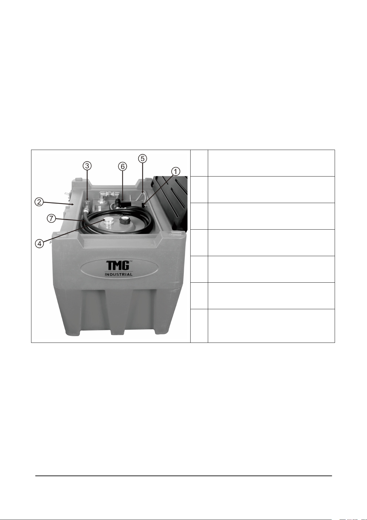
dump the fuel, using, for example,a cable with pliers. For ease of understanding, the operations
are proposed with the indication in () of the component highlighted in Picture
*
Check that the switch of the electric pump (6) is switched to"O".
*
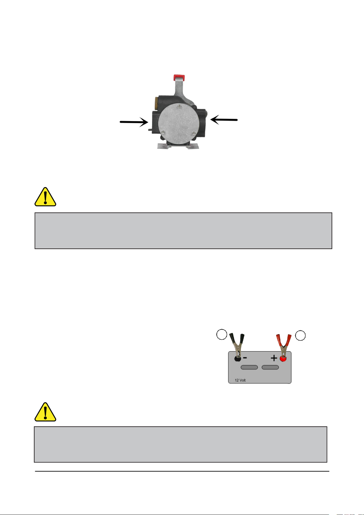
Enable the power line connecting the clamps to the terminals of the battery, respecting the
polarities(red+, black-).
*
Unroll the hose (7) and insert the gun (3) in the destination tank,after locking the lever in the "open"
position.
*
Start the electric pump by placing the pump switch to "I".
*
Proceed with transferring within max.2 minutes after the switch on of the electric pump
*
Monitor the achievement of the desired degree of filling, or wait for the overflow stop in case
of automatic gun. After completing emptying, perform the operations described in sequence:
*
Switch off the pump switch on the pump body(pos. "0").
*
Drain liquid still pressing down for a few moments the gun handle(3), in order to discharge any
residual pressure in the discharge pipe.
*
Store the hose (7) properly rolled in the position shown in the photo(see Picture ), placing the
gun (3) into the recessed area of the tank.
*
Disconnect the power supply by disconnecting the clamps from the terminals of thebattery.
5.PRECAUTIONS
Each type of operation should be avoided/suspended in stormy weather in place or imminent, The
employer is responsible, pursuant to art, to prepare appropriate risk assessment in this regard. It is
considered useful to provide in each case the following minimum safety information:
Each object with an elevation predominant compared with the surrounding area has a greater chance

WWW.TMGINDUSTRIAL.COM P06/18 Toll Free:1-877-761-2819
of being struck by lightning: so the use of the "machine" near or under the shelter of trees, towers or
pylons must be considered at risk and, when placed above the vehicle floor, the container can represe
nt itself the subject of predominant elevation relative to the surrounding area.
Not necessarily the risk of electrocution is due 1o the fact that container's direct target of lightning.
The mere proximity to an exposed structure constitutes danger since the current of the lightning,
after hitting its target, disperses in the soil, so if you are near the hit structure and you are in contact
with the ground you may come in contact with the dispersing current and be damaged,
In case of lightning that hit a container with flammable liquid, in addition to the direct physical
damage (death), there is a real risk of fire in the container.
During transport, the power line derived from vehicle battery must be disconnected.
6.SAFETY INSTRUCTIONS
In addition to those already given in several previous chapters, we remind the user the following import
ant requirements, where non-com-pliance may result in extremely serious consequences:
DO NOT USE IN PLACES WHERE THERE MAY BE THE DANGER OF THE FORMATION OF
EXPLOSIVE ATMOSPHERES (In the case of tank with ATEX marking follow the prescription
Imposed by marking)
ALWAYS KEEP AT LEAST ONE 2KG ABC POWDER EXTINGUISHER AVALABLE OR
EQUIVALENT ONE
A IN CASE OF OUTBREAK OF FIRE, IMMEDIATELY ISOLATE THE TANK CLOSING THE SHUT-
OFF VALVE ON ASPIRATION

WWW.TMGINDUSTRIAL.COM P07/18 Toll Free:1-877-761-2819
At the end of the transfer switch the electric pump off within Tax 2 minutes, and discharge the residual
pressure acting on the gun tor a short residual delivery.
Store your gun and hose only after verifying the absence of drips
During transport, the power line must be disconnected and the shut-off valve closed.
For transportation,fasten the tank with belts to prevent any movement on the loading platform
Fuel vapour/air mixtures can ignite above 55℃, in the presence of any rigger type, such as the sparks
caused by the contact of electrical connectors clamp meter with the battery terminals.
It is therefore important, particularly in the summer, to take the filling precautions:
- Do not expose e connectors and the battery to direct sunlight, which could lead to high localised
temperatures.
- Always keep the tank at a distance of at least 1m from battery.
- Always work in open and ventilated places to prevent the formation and accumulation of flammable
vapors.
- In case of leaks or pills at diesel refrain from transferring if before thoroughly cleaning the affected
surfaces.
7.MAINTENANCE
7.1.CONTROLS
It is your responsibility to take charge of maintaining integrity and efficiency of the TANK and its devices
and equipment,in particular periodically check:
-Periodically inspect the state of wear of the surfaces of the housing,with particular regard to those of the
bottom,exposed to wear by friction with lifting systems.
-the perfect sealing of the tank, paying the utmost attention to possible loss or leakage of the fluid at the
nozzle, faucet, suction pipes and discharge valves.
-the good condition of the inscriptions on the wrapping identifying the material and its harmfulness and, if
damaged, replace them with new ones of the same type and in the exact same position.
7.2.CLEANING
The tank and its emptying device should be kept clean both by external agents (dirt, dust, etc ), and
any accidental spills of dangerous materials on the occasion of fills, flushes, loss.
For cleaning use non-corrosive products tor metal parts and for electrical cables and plastics in

general, preferring neutral or slightly alkaline greasing products. Steam systems can be used
(puli-vapor steamer),provided that the jet is not directed against parts of the electrical system or
against the plates and/or adhesive plates applied on the body of than and on the metal frame
of the emptying device.
7.3.TAMPERING
In addition to the provisions in 8, for no reason you are allowed to change the tank as regards the
characteristics of the electric emptying device; in particular:
It is strictly forbidden to replace equipment with other components different from the
original ones,without the manufacturer's warranty as regards pressure resistance.
8.SPARE PARTS
Any modification or replacement of parts of the housing, as a result of damage, accident or tampering, is
allowed only in centres authorised by it as the operation is configured as"reconditioning".
The use of non-original spare parts voids the manufacturer's warranty,if in course.
It is strictly forbidden manufacturer's warranty as regards pressure resistance.to replace equipment wit
h other components different from the original ones, without the manufacturer’s warranty as regards
pressure resistance.
9.FUEL PUMP
9.1 INSTALLATION
The pump is designed to be portable for your convenience and safety. It features a unique hinged
vane design that eliminates the need for a bypass valve. Because of its unique nature, the pumps
can be installed / used in several configurations. Read each configuration prior to beginning
installation.
IMPORTANT! Do not use check valves or foot valves; valves reduce rate of flow and performance of the
pump.
WARNING! The pump is designed primarily for portable applications, using skid tanks, drums, barrels, and
other portable fuel containers to supply fuel. It is paramount to anchor the supply tank or drum to which the
pump is connected to ensure no movement occurs in transit or while fueling. Failure to secure the tank or
drum can cause unexpected and uncontrolled movement, resulting in damage, injury, death, and potential
fire or explosion.
WWW.TMGINDUSTRIAL.COM P08/18 Toll Free:1-877-761-2819

DANGER! Fumes accumulated while fueling create an Explosive Atmosphere. It is CRITICAL that all
possible sources of ignition be removed to a safe distance or extinguished. Sources of ignition would
include (but not be limited to) open flames, cigarettes, static discharge, or electrical connections that can
create a spark. Explosion, fire, and severe injury or death will occur if the explosive vapors are ignited.
9.2 FUELING SAFETY
Fumes accumulated while fueling create an Explosive Atmosphere around the tank that is being filled. To
avoid possible explosion of accumulated vapors, it is critical to keep possible sources of spark / ignition
at safe distances from the fuel vapors.
The accompanying diagram
shows minimum safe distances
for safe fueling. 10’ is the
minimum safe distance between:
• Power source and fuel supply.
• Power source and tank being filled.
• Power source and pump.
9.3 FLANGE CONFIGURATION
CAUTION! Always be certain the power switch is accessible after reconfiguring the inlet and outlet ports.
WARNING! Be certain seals and screen are properly positioned and clean any time the flanges are
reconfigured. Improperly installed or dirty seals or screens could cause leaks and the potential for fire or
explosion
WWW.TMGINDUSTRIAL.COM P09/18 Toll Free:1-877-761-2819

DANGER! Be certain the power switch is “OFF” prior to connecting the battery clamps / power cables to the
power source or installing the cable into the pump to prevent unexpected starting of the motor. Unexpected
motor start can cause unintended discharge of fuel, creating an explosion and fire hazard.
The inlet and outlet flanges of your pump can be configured horizontally.
9.4 DC POWER CONNECTION
Inspect power cable before each use! Damage to the outer jacket of the cable that exposes wiring
requires replacement of the power cable.
Install power cable by aligning flat on plug with front of pump. HAND TIGHTEN ONLY! The power cable
terminates in black, and red clamps. All two clamps must be used.
1.Connect the black (negative) clamp to the
negative post of the DC power source.
2.Connect the red (positive) clamp to the
positive post last.
Clamps should be disconnected in reverse order.
9.5 POWER SWITCH
Red
Black
1
2
DANGER! Be certain the power switch is “OFF” prior to connecting the battery clamps / power cables to
the power source or installing the cable into the pump to prevent unexpected starting of the motor.
Unexpected motor start can cause unintended discharge of fuel, creating an explosion and / or fire hazard.
WWW.TMGINDUSTRIAL.COM P10/18 Toll Free:1-877-761-2819
Inlet
Outlet

The pump features a sliding ON /OFF power switch. The switch is located on top of the pump at the back
of the pump housing. To operate the pump, push the switch to the desired position. Push “ON” to operate
the pump, and push “OFF” to turn the pump off.
NOTE: The side where the switch button is depressed is the function the switch is performing.
9.6 OPERATIONAL SAFETY
WARNING! The pump body can become hot with extended use. Always use the handle to lift and carry the
pump when moving it. Use caution when gripping the handle as exposed skin may be burned if it contacts a
hot pump.
IMPORTANT! The RD series pump uses thermal overload protection to prevent overheating. If the pump
shuts off due to thermal overload, turn the power switch “OFF”. Once the pump cools the switch can be set to
“ON” again to reset the thermal protection.
Pump OFF
Pump ON
WARNING! NEVER disconnect the power cable from the pump while pump is switched on or connected to a
power source. ALWAYS switch the pump off and disconnect all the clamps from the power source PRIOR
to disconnecting the power cable from the pump. Electrical shorts, sparks, or unexpected start up canoccur.
DANGER! DO NOT use pump in enclosed areas when pumping hazardous or explosive fluids. Pumping
area should be well ventilated. Concentrated vapors in an enclosed area are noxious and highly explosive!
WWW.TMGINDUSTRIAL.COM P11/18 Toll Free:1-877-761-2819

WARNING! Use caution when operating or carrying the pump. The hoses and electrical power cable can
be a trip hazard; caution should be exercised any time the pump is moved with the hoses and power cable
connected to avoid tripping or entanglement.
DANGER! DO NOT open or attempt to repair the motor on your pump. Return it to the place of
purchase for service. Opening the motor case will compromise the integrity of the Explosion Proof
construction and void any existing warranty, approvals, and certifications (i.e.: ATEX, UL listing, CE, etc.).
9.7 TROUBLESHOOTING
This Troubleshooting guide provides basic diagnostic assistance.
WARNING! Pump assembly can become hot with extended use. Use caution when handling the pump after
use; always use the handle to move or hold the pump. Pump has 30 minute on / 30 minute off duty cycle.
DANGER! Disconnect all power prior to performing any service or maintenance. Failure to disconnect the
power may cause electrical shock, or unexpected starting of the motor, resulting in injury or death.
CAUTION! DO NOT operate the pump if any part of the explosion proof motor construction is missing or
compromised. Disassembly of the motor will compromise the explosion proof design and void any warranty.
CAUTION! DO NOT operate the pump dry for more than 30 seconds. DO NOT operate the pump in bypass
more than 5 minutes. Damage to the pump will occur.
WWW.TMGINDUSTRIAL.COM P12/18 Toll Free:1-877-761-2819

Pump runs slowly.
Symptom
Cause
Cure
Pump won’t
prime.
Suction line problem.
Check suction line for leaks or restrictions; it may be
too small in diameter, too long, not air tight, or too low
vertically.
Vanes sticking.
Check vanes for nicks, damage, obstructions,
or excess wear. Replace as necessary.
Excessive rotor, vane, rotor
cover, or housing wear.
Inspect rotor, vanes, rotor cover, and housing for
excess wear; replace as necessary.
Inlet / Outlet blocked.
Check pump, hose, nozzle, and filter / strainer
for blockage.
Vapor lock.
Reduce vertical or horizontal distance from pump
to liquid.
Power connections reversed.
Correct power connections.
Low capacity.
Excessive dirt in screen.
Remove and clean screen.
Suction line problem.
Check suction line for leaks or restrictions; it may be
too small in diameter, too long, not air tight, or too low
vertically.
Excessive rotor, vane, rotor
cover, or housing wear.
Inspect rotor, vanes, rotor cover, and housing for
excess wear; replace as necessary.
Hose or nozzle damage.
Replace hose or nozzle.
Low fluid level.
Refill tank.
Incorrect voltage.
Check incoming line voltage while pump is running.
Vanes sticking.
Check vanes for nicks, damage, obstructions,
or excess wear. Replace as necessary.
Wiring problem.
Check for loose connections.
Motor problem.
Return to place of purchase.
Motor stalls /
fuse blows.
Short in wiring.
Inspect electrical cable for shorts and replace
as necessary.
Excess rotor or vane wear.
Check vanes for nicks, damage, obstructions,
or excess wear. Replace as necessary.
Pump rotor lock-up.
Clean and inspect rotor and vanes.
Debris in pump cavity.
Clean debris from pump cavity.
Components swell from
pumping water.
Let pump dry completely.
Fluid leakage.
Bad o-ring gasket.
Check all o-rings.
Bold text indicates repairs that are not serviceable by the owner; pump must be returned to the point
of purchase for repairs.
WWW.TMGINDUSTRIAL.COM P13/18 Toll Free:1-877-761-2819

TROUBLESHOOTING (cont’d)
Symptom
Cause
Cure
Fluid leakage.
Bad o-ring gasket.
Check all o-rings.
Bad shaft seal.
Return to place of purchase.
Incompatible fluid.
Refer to wetted parts list (page 10).
Loose fasteners.
Tighten fasteners.
Inadequate plumbing seals.
Reseal plumbing connections.
Pump hums
but will not
operate.
Motor failure.
Return to place of purchase.
Motor
overheats.
Pumping high viscosity fluids.
These fluids can only be pumped for short periods of
time (less than the 30 minute duty cycle).
Clogged screen.
Remove and clean screen.
Restricted suction pipe.
Remove and clean pipe.
Motor failure.
Return to place of purchase.
Pump rotor lock-up.
Clean and inspect rotor and vanes.
No power.
Check incoming power.
Switch failure.
Return to place of purchase.
Incorrect or loose wiring.
Check wiring / connections.
Motor
inoperative.
No power.
Check incoming power.
Switch failure.
Return to place of purchase.
Motor failure.
Return to place of purchase.
Motor overheated.
Switch off and allow to cool.
Incorrect or loose wiring.
Check wiring / connections.
Fuse has blown.
Replace 30A fuse.
Bold text indicates repairs that are not serviceable by the owner; pump must be returned to the
point of purchase for repairs.
9.8 Cleaning the Inlet Screen
Regular inspection and cleaning of the inlet screen on your series pump helps maintain performance and flow.
Access the screen by removing the inlet flange as described on .Clean, rinse, and dry the screen throughly
before re-installing.
Inspect the screen, seals, and flange area for debris and damage. If screen or O-rings are damaged, replace
with kit
WWW.TMGINDUSTRIAL.COM P14/18 Toll Free:1-877-761-2819

10.TECHNICAL INFORMATION
Motor
Power-DC
12V
HP(horsepower) rating
5/16HP
Amps
19A
RPM
2800
Duty cycle
30min. ON/ 30 min. OFF
Power cable length
6-1/2’
Power cable DC battery connectors
Yes
Pump
Type- rotary, diaphragm, gear, vane
Rotary Hinged Vane
Flow Rate (with supplied hose / nozzle)
Up to 10 GPM
Flow Rate open flow - no hose or nozzle
Up to 15 GPM
Max discharge pressure
16 PSI
Head- Max (ft)
20’
Max suction(ft)
10’
Inlet - Size / Thread
1” NPT
Outlet – Size / Thread
1” NPT
WWW.TMGINDUSTRIAL.COM P15/18 Toll Free:1-877-761-2819

Exploded Drawings
Main Exploded Drawings
Main Past List
Ref#
Description
Qty
Ref#
Description
Qty
1
Cover plate
1
9
Suction hose
1
2
Fuel tank
1
10
Automatic gun
1
3
Connector 1
1
11
Connector 6
1
4
Connector 2
1
12
Pressure gauge
1
5
Connector 3
1
13
Vent
1
6
Connector 4
1
14
Delivery hose
1
7
Connector 5
1
15
Connector 7
1
8
Oil pump
1
WWW.TMGINDUSTRIAL.COM P16/18 Toll Free:1-877-761-2819

Pump Exploded Drawings
WWW.TMGINDUSTRIAL.COM P17/18 Toll Free:1-877-761-2819

Pump Past List
Ref#
Description
Qty
Ref#
Description
Qty
1
Motor 12V DC
1
15
Handle handle
1
2
Flat keys
1
16
Handle set
2
3
Deep groove ball bearings
6200-2RZ
1
17
Cross groove head screws M5X120
1
4
Oil seal 26X10-7
1
18
Insurance box
1
5
Pump body
1
19
Rear cover
1
6
Base
1
20
Switch
1
7
Leaf blade rotor
5
21
Tightening nut
1
8
Leaf blade
1
22
Positioning set
1
9
O loops
1
23
Lock the nut
1
10
Pump cover
1
24
Two-phase cable 12X2000
1
11
Plastic spool
1
25
Zero wire clip
1
12
Spring 11X40mm
1
26
Fire clamp
1
13
O loops 18X2.65
1
27
Cross groove head screws M5X55
2
14
Valve cover 27-1/2 H60
1
WWW.TMGINDUSTRIAL.COM P18/18 Toll Free:1-877-761-2819
Table of contents
Other TMG Water Pump manuals
Popular Water Pump manuals by other brands

Wolf
Wolf Solar pump assembly 10E Operation instructions for contractors

Pearl
Pearl MINISUB Installation and operating instructions

Efco
Efco MP 300 Operators instruction book

EasyCare
EasyCare HARVEST 2 General User/ Safety Guide

Sandpiper
Sandpiper MSA2 Service manual

PSG Dover
PSG Dover WILDEN Accu-Flo A200 Engineering, operation & maintenance

Silverline
Silverline 104616 quick start guide

Franklin Electric
Franklin Electric I Series Installation, operation and maintenance manual

Adixen
Adixen MAGPOWER operating instructions

DROPSA
DROPSA 999 Series User and maintenance manual

Linear Technology
Linear Technology LTC3218 quick start guide

Ruris
Ruris Aqua 1090 manual