TMP Alpha Solar User manual

Unit 6 Trident Drive, Wednesbury,
West Midlands. WS10 7XB
0208 744 8201
www.tmp.solutions
1 of 4
Alpha Solar
Installation Guide
IMPORTANT : This product is to be installed and maintained by qualified personnel only.
TMP Solutions take no responsibility for damage or injury incurred during the installation or maintenance.
It may be possible to install the kit on a 76mm diameter column, but access apertures vary in size and shape
and not all 76mm diameter columns will be suitable. The installer is responsible for checking that the chosen
column is structurally suitable for the application and that the kit fits.
Kit Contents
Solar Panel
Apollo Alpha Sign Light
(Ftted with mid post mount assembly)
Cables
(Prefitted and terminated with plugs/sockets)
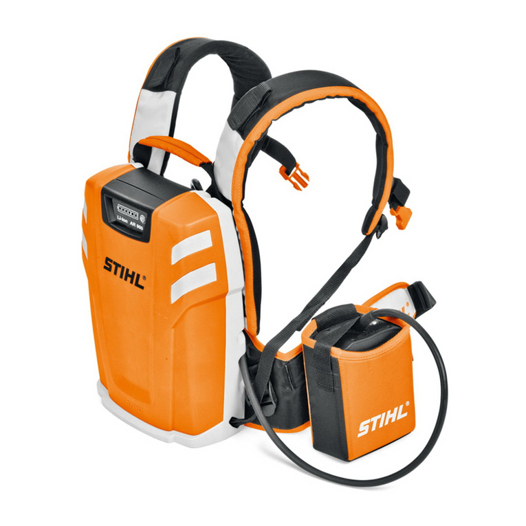
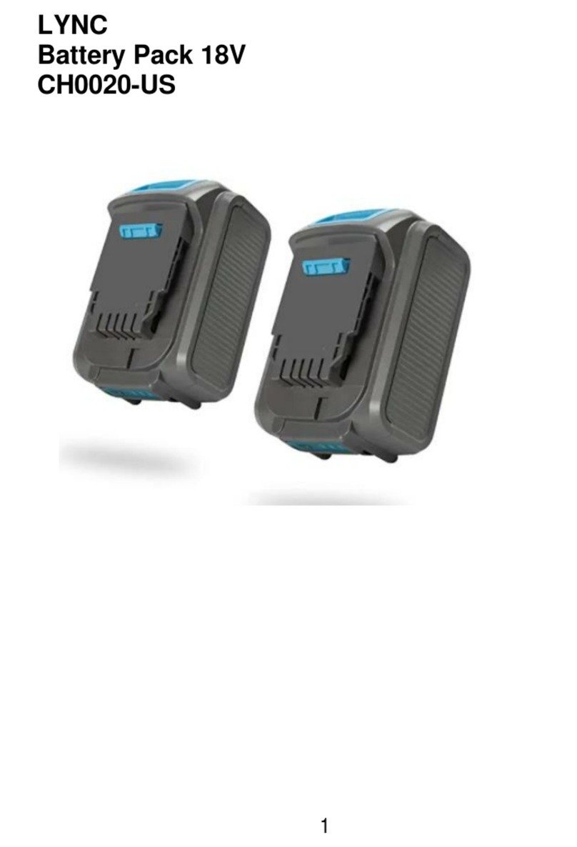
Battery Pack
(With charge controller)
Tools Needed (Not supplied)
Gloves and appropriate PPE
Column key
13mm Spanner
Compass
Drill with 10mm bit
Column cutting tool
Sundries Required (Not supplied)
2 x Sign Channel Brackets Post Cap (internal style) 2 x 10mm Grommets 2 x Jubilee Clips

2 of 4
Safety
Electrical safety: The nominal voltage is 12V dc, therefore the system is inherently safe. The maximum system
voltage is approximately 20V dc from the solar module when it is not connected to a load.
Batteries: The battery pack weighs approximately 8.4 kg, proper manual handling should be observed throughout
the installation.
Explosives: The batteries produce a small amount of hydrogen gas whilst charging, and for some time after.
Hydrogen is explosive in a wide range of concentrations of air so it is important to ensure the lighting column is well
vented. If the access cover forms a seal, drill a 10mm vent hole.
Fire: The batteries have a low internal resistance and will generate a lot of heat when short-circuited. The battery
packs are equipped with a 3A fuse which must only be replaced by an identical fuse (automotive, 3A, mini-blade).
Chemical Burns: The batteries contain sulphuric acid which can cause skin and eye damage if it leaks out of a
damaged battery. In case of contact seek professional medical advice immediately.
3.7m MAX
Cut post to maximum 3.7mChoose an un-shaded location.
Feed wire from solar panel through
hole in the column (use grommet)
SOUTH
Tighten the module to the pole
using channel clamps. ENSURE
MODULE IS FACING SOUTH
145mm
SOUTH
Drill 10mm hole in column 145mm
from top facing due SOUTH
If using an existing column make
sure any mains power connections
have been removed or terminated.
1 2 3
654

Insert 3A fuse into fuse holder,
check lights on the charge
controller (after 5 seconds the
green LED should be on and the
2 red LEDs should be off)
To Sign Light
Plug in 3 way connector
(from Alpha Sign Light)
To Solar Panel
Plug in 2 way connector
(from Solar Panel)
3 of 4
Cable ties can be
used to lift
Secure mounting post using Jubilee
Clips (not supplied) and tighten
Check operation and fit access
cover, ensure adequate ventilation
Insert battery pack into column and
use hook to hang over back board,
TAKE CARE NOT TO DAMAGE
BATTERIES
10 11 12
151413
Feed wire from luminaire through
hole in the column (use grommet)
Fit post cap onto column
Drill 10mm hole for Alpha Sign Light
in required position on column
7 8 9

Version 05/02/2020
We operate a policy of continuous product development and reserve the right to change or improve specification without prior notice. E & OE.
© 2020 TMP Solutions All Rights Reserved. TMP Solutions and TMP Professional Services are the trading names of Traffic Management Products Limited,
company number 3207588, with our registered offices at TMP Solutions Unit 4, Nightingale Road, Horsham, West Sussex. RH12 2NW.
Commisioning
During Daylight
The green LED should be flashing slowly. Depending
upon the battery condition, one of the red LEDs may
also be on.
The luminaire should be on. To check the function of
the luminaire during daytime, cover the solar module
(with cardboard or blanket). After 1 minute the green
LED should become solid, and after a further 4
minutes the luminaire should turn on.
During Night Time
The green LED should be on solid (not flashing).
Depending upon the battery condition, one of the
red LEDs may also be on. The luminaire should be on.
Battery not connected or fuse blown
Normal operation : Night-time detected
Normal operation : Day-time detected
Luminaire fault
Battery low : luminaire brightness reduced
Fault : reconnect in correct sequence
Note: The system takes up to 1 minute to detect the change between
day and night phases, plus an additional 4 minutes for the luminaire to
switch on and off. This is to prevent false day and night detection.
OFF
ON
FLASH
OFF
OFF
OFF
OFF
OFF
OFF
OFF
OFF
ON
ON
ON
ON
FLASH
Maintenance
Battery Pack
The battery pack is expected to last 3 to 4 years, but this depends on installation location. The battery pack can be easily
replaced as follows:
1. Remove the lighting column access cover
2. Disconnect the 2 way plug
3. Disconnect the 3 way plug
4. Remove the fuse from the fuse holder
5. De-couple the bullet crimps from the battery pack
6. Cut the 3 cable ties securing the battery pack in place
7. Refit in the reverse sequence (always fit the fuse before connecting cables)
8. Recheck column ventilation
Solar Panel
The solar module should be periodically inspected for damage. The inspection regime should be set according to prevailing
conditions. Systems installed in areas with significant levels of atmospheric pollutants or excessive wind loads should be
inspected more regularly.
The module is manufactured on anodised, marine grade aluminium to minimise corrosion. Check that the channel clamps are
free from corrosion and that the sign channels are securely fixed to the solar panel.
It is recommended that the front of the module is cleaned during inspection.
Need help? 0208 744 8201
