EVERVOLT EVHB-I7 User manual

UL
®
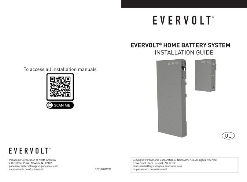
EVERVOLT HOME BATTERY SYSTEM
INSTALLATION GUIDE
Copyright © Panasonic Corporation of North America. All rights reserved.
2 Riverfront Plaza, Newark, NJ 07102
panasonicbatterystorageus.panasonic.com
na.panasonic.com/us/evervolt
Panasonic Corporation of North America
2 Riverfront Plaza, Newark, NJ 07102
panasonicbatterystorageus.panasonic.com
320102081802
na.panasonic.com/us/evervolt
To access all installation manuals

TABLE OF CONTENTS
1 ABOUT THIS MANUAL..........................................................................................1
1.1 SCOPE OF VALIDITY........................................................................................1
1.2 TARGET GROUP...............................................................................................1
1.3 SYMBOLS USED..............................................................................................1
1.4 ABOUT EVERVOLT HOME BATTERY SYSTEM................................................2
1.4.1 SYSTEM OVERVIEW................................................................................3
1.4.2 SOLUTIONS............................................................................................4
2 SAFETY..................................................................................................................5
2.1 GENERAL SAFETY INSTRUCTIONS...............................................................5
2.2 IMPORTANT SAFETY INSTRUCTIONS...........................................................5
3 SPECIFICATION....................................................................................................9
3.1 SPECIFICATION OF EVERVOLT HYBRID INVERTER......................................9
3.2 SPECIFICATION OF BATTERY.......................................................................11
3.3 SPECIFICATION OF SMART BOX..................................................................11
4 SITE REQUIREMENTS AND PRE-INSTALLATION GUIDANCE..........................13
4.1 PHYSICAL REQUIREMENTS......................................................................13
4.2 DIMENSIONS OF THE SYSTEM.................................................................13
4.3 INSTALLATION SPACE REQUIREMENT....................................................16
4.4 INSTALLATION ENVIRONMENT REQUIREMENT......................................20
5 PREPARATION FOR INSTALLATION...................................................................21
5.1 PACKING LIST OF INVERTER........................................................................21
5.2 PACKING LIST OF BATTERY..........................................................................23
5.3 PACKING LIST OF SMART BOX.....................................................................25
5.4 TOOLS REQUIRED .........................................................................................26
6 PLAN THE INSTALLATION SITE..........................................................................27
7 MECHANICAL INSTALLATION............................................................................30
7.1 OVERVIEW OF INSTALLATION SCHEMES....................................................30
7.2 INSTALLATION METHODS.............................................................................38
7.3 FLOOR-MOUNTING.........................................................................................38

About this Manual
1
1.1 Scope of Validity
1 About this Manual
7.4 WALL-MOUNTING..........................................................................................59
8 WIRING CONNECTION ON THE INVERTER........................................................62
8.1 OVERVIEW OF ALL ELECTRICAL WIRING METHODS..................................62
8.2 POWER CONNECTION...................................................................................64
8.2.1 PV CONNECTION..................................................................................66
8.2.2 GRID CONNECTION..............................................................................68
8.2.3 BATTERY CONNECTION.......................................................................70
8.3 GROUND CONNECTION...............................................................................72
8.4 COMMUNICATION CONNECTION................................................................74
8.4.1 MAKE CONNECTION TO ANOTHER INVERTER/SB............................74
8.4.2 EPO CONNECTION...............................................................................80
8.4.3 RGM (METER X) CONNECTION (OPTIONAL).......................................80
8.4.4 EXTERNAL ELECTRICITY METER CONNECTION (OPTIONAL)...........80
8.4.5 RSD TRANSMITTER CONNECTION.....................................................80
8.4.7 MONITORING CONNECTION (OPTIONAL)..........................................82
9 WIRING CONNECTION ON THE EV-SB.............................................................83
9.1 INSTALL A MAIN BREAKER (PURCHASED SEPARATELY)......................... 83
9.2 INVERTER, GENERATOR, LOAD AND GRID CONNECTION....................... 85
9.3 MAKE COMMUNICATION CONNECTION.....................................................92
10 CLOSE WIRING COVER AND TURN ON THE SYSTEM....................................98
10.1 CHECK BEFORE TURN ON THE SYSTEM..................................................98
10.2 TURN ON THE SYSTEM..............................................................................98
10.3 SHUT DOWN THE SYSTEM.........................................................................99
11 INDICATOR LIGHT AND BUTTON...................................................................100
12 TROUBLESHOOTING.......................................................................................105
13 MAINTENANCE...............................................................................................117
14 COMMISSION THE SYSTEM............................................................................120
APPENDIX A: WIRING AND BREAKER REQUIREMENT.....................................123
APPENDIX B: EPO CONNECTION STEPS...........................................................128
APPENDIX C: METER Y CONNECTION DIAGRAM..............................................129
APPENDIX D: SYSTEM WIRING DIAGRAM.........................................................130
This manual is an integral part of the EVERVOLT Home Battery System including
EVERVOLT Hybrid Inverter, battery and SmartBox. It describes the assembly,
installation, commissioning and maintenance. Please read it carefully before
operating. Store this manual where it will be accessible at all times.
WARNING!
Save these instructions. This manual contains important
instructions for EVERVOLT Hybrid Inverter that shall be followed
during installation of the system.
1.2 Target Group
This manual is for qualified electricians. The tasks described in this manual
should only be performed by qualified electricians.
1.3 Symbols Used
WARNING!
“Warning” indicates a hazardous situation which, if not avoided, could
result in serious injury or death.
DANGER!
“Danger” indicates a hazardous situation which, if not avoided, will
result in serious injury or death.
CAUTION!
“Caution” indicates a hazardous situation which, if not avoided, could
result in minor to moderate injury.
NOTE!
“Note” provides tips for the optimal operation of our product.
The following types of safety instructions and general information appearing in
this document are described below:
8.4.6 PARALLEL CONNECTION ...................................................................81

System overview of EVERVOLT Home Battery System
About this Manual
About this Manual
1.4 About EVERVOLT Home Battery System 1.4.1 System Overview
3
2
EVERVOLT Hybrid inverter is a transformerless type without galvanic isolation. It is
designed and certified to fulfill the directives of ANSI/NFPA 70, NEC 690.41, UL 1741,
UL 1741 SA17 & SA18, IEEE 1547 and IEEE 1547.1. The inverter converts the DC power
generated by PV strings into AC power and stores the energy into the battery bank or
feeds the power into the power grid.
With the device, you have acquired the system that can be used to power critical loads
during a grid outage by using a battery and realize automatic transfer from grid
connection mode to off grid mode or from off grid mode to grid connection model by
using Smart Box (EV-SB). The inverter also has the ability to use power generated
from PV arrays along with other string inverter.
EVERVOLT Hybrid Inverter
The EVERVOLT Hybrid inverter manages battery and system energy.
PV Array
A PV array works in MPPT mode.
For 7.6 kW inverter, there can be a maximum of three PV strings.
RSD
The RSD provides an automatic disconnect of residential or small commercial PV
systems, fully compliant with the rapid shutdown requirements of National Electric
Code (NEC), ANSI / NFPA 70 Sections 690.12.
Battery
The EVERVOLT Hybrid inverter should be coupled with a high voltage battery.
The battery communicates with inverter via BMS and must comply with the specification
of UL 1973.
SmartBox
The SmartBox supports multi-inverter parallel connection, controls disconnection
of house loads from the grid in case of a power outage and integrates the energy
meter, microgrid interconnection device and generator to enable grid-tied solar backup.
myEVERVOLT application
myEVERVOLT application is an intelligent, multifunctional monitoring platform that can be
accessed either remotely or through a hard wired connection. With the myEVERVOLT
application, the operators and installers can always view key and up to date data.
EVERVOLT Hybrid inverter and battery
Utility Grid
SmartBox
App
PV1 PV2 PV3
Generator
Load
Main panel
Meter
myEVERVOLT
DC Power
AC Power
Communication
Cloud
RSD RSD RSD

About this Manual
2 Safety
2.2 Important Safety Instructions
WARNING!
This document does not replace and is not intended to replace any
local, state, provincial, including without limitation applicable in the
jurisdiction of installation. EVERVOLT assumes no responsibility for
the compliance or non-compliance with such laws or codes in
connection with the installation of the product.
Before installing or using the product, read all the instructions,
cautions, and warnings in this manual. Failure to do so or to follow
any of the instructions or warnings in this document can result in
electrical shock, serious injury or death, or may damage the
product.
Before connecting the product to the electrical utility grid, contact
the local utility company.
All work must be carried out by a qualified electrician. Children
should be supervised to ensure that they do not play with the
appliance.
Safety
DANGER!
Danger to life due to high voltages in the product!
ŸWhole home backup solution
Up to 4 EVERVOLT Hybrid Inverters parallel
Up to 4 battery modules stackable per inverter
Homeowners are automatically provided with backup power in the
event of grid interruption to whole home loads.
ŸPartial home backup solution
Up to 4 EVERVOLT Hybrid Inverters parallel
Up to 4 battery modules stackable per inverter
Homeowners are automatically provided with backup power in the
event of grid interruption to selected loads.
1.4.2 Solutions
5
4
This manual contains important instructions for EVERVOLT Hybrid Inverter
that should be followed during installation and maintenance for the
inverter.
2.1 General Safety Instructions
EVERVOLT Hybrid Inverter is designed and tested to meet all applicable
North American safety standards. However, like all electrical and electronic
equipment, safety precautions must be observed and followed during installation
and operation of the EVERVOLT Hybrid Inverter to reduce the risk of personal
injury and to ensure a safe installation.
Installation, commissioning, service, and maintenance of EVERVOLT Hybrid
Inverter must only be performed by certified installer that are licensed and /
or satisfy state and local jurisdiction regulations.
Before starting installation or commissioning, read the entire manual carefully to
ensure correct and safe installation or commissioning. And keep the user manual
in a safe place.
All US electrical installations must comply and be in accordance with all the state,
local, utility regulations, and National Electrical Code ANSI/NFPA 70.

EVHB series only supports a certain type of lithium-ion battery
(Manufacturer certified battery)!
CAUTION!
Do not expose system to ambient temperatures above 140° F (60° C)
or below -13° F (-25° C).
WARNING!
Do not install the system in a corrosive environment where it may be
exposed to ammonia, corrosive gases, acids, or salts (eg: chemical
plant, fertilizer storage areas, tanneries, near volcanic ash eruption).
WARNING!
Safety Safety
Do not disassemble any parts of the product which are not
mentioned in the installation guide. It contains no user-serviceable
parts. See warranty for instructions on obtaining service. Attempting
to service the device by yourself may result in a risk of electric shock
or fire and will void your warranty.
WARNING!
Do not operate the device when the device is running.
WARNING!
CAUTION!
Only accessories shipped with the product are recommended to use.
Using other accessories may void warranty.
CAUTION!
Possible damage to health as a result of the effects of radiation!
Do not stay closer than 7.87 in / 20 cm to system for a long time.
CAUTION!
Danger of burn injuries due to hot enclosure parts!
During operation, the enclosure may become hot.
CAUTION!
Risk of electric shock from energy stored in the capacitor.
Never operate on the inverter couplers, the Mains cables, battery
cables, and PV cables when power is applied. After switching off the PV,
battery and Mains, always wait for 5 minutes to fully discharge the
intermediate circuit capacitors discharge before unplugging DC, battery
and Mains couplers.
7
6
WARNING!
Do not attempt to open, disassemble, repair, tamper with or
modify the product. The product and its components are not
user serviceable.
The inverter input and output circuits are isolated from the enclosure.
This system does not include an isolation transformer and should be
installed with an ungrounded PV array in accordance with the
requirements of ANSI / NFPA 70, NEC 690.41.
Equipment grounding is the responsibility of the installer and must be
performed in accordance with all applicable Local and National
Codes.
WARNING!
Before operating the inverter, ensure that the inverter is grounded
properly. This product must be connected to a grounded, metal,
permanent wiring system, or an equipment-grounding conductor
must be run with the circuit conductors and connected to the
equipment grounding terminal or lead on the product.
WARNING!
When a ground fault is indicated, normally grounded conductors
may be ungrounded and energized or normally ungrounded
conductors may be grounded.
WARNING!

Specification
9
Safety
3 Specification
3.1 Specification of EVERVOLT Hybrid Inverter
8
PV Input
AC Input/Output
Start input voltage [V]
Model
Max. Inverter PV Power[W]
15200
Max.DC voltage [V]
Norminal DC operating voltage [V]
Max. input current [A]
Max. short circuit current [A]
MPPT voltage range [V]
MPPT voltage range [V](full load)
11400
550
360
A:16/B:16/C:16
A:20/B:20/C:20
90-500
120
235-500
EVHB-I7
AFCI
No. of MPP trackers
Strings per MPP tracker
DC disconnection switch
3
Yes
Yes
A:1/B:1/C:1
General Data
General
Topology
Dimensions with Safety Switch
Weight with Safety Switch [lb(KG)]
Cooling concept
33.1*15.7*5.7840*400*145
75 (34)
Natural convection with internal fan
Transformerless
Communication
Revenue Grade Data, ANSIC12.20
Warranty [Years]
RS485, CAN, WIFI
Optional
12
(WxHxD) [in(mm)]
Maximum output fault peak current
Model
Norminal AC power [VA]
7608
Max. apparent AC power [VA]
Rated grid voltage [V]
Rated grid Frequency [Hz]
Norminal AC current [A]
Max. AC current [A]
Maximum output fault current and
7608
240
50/60
31.7
48/90
515/5
Displacement power factor
Total harmonic distortion
Parallel operation
0.8 leading to 0.8 lagging
<3%
Yes
duration [A/ ms]
and duration [A/ ms]
31.7
(THD, rated power)
Battery safety instructions
EVERVOLT Hybrid inverter should be coupled with a high voltage battery.
The battery must comply with UL 1973 and must be EVERVOLT certified.
As accumulator batteries may contain potential electric shock and short-
circuit current dangers, to avoid accidents that might be thus resulted, the
following warnings should be observed during battery replacement:
ŸRisks of explosion:
Do not subject the battery module to heavy impacts.
Do not crush or puncture the battery module.
Do not dispose of the battery module in a fire.
ŸRisks of fire:
Do not expose the battery module to temperatures in excess of 140°F.
Do not place the battery module near a heat source, such as a fireplace.
Do not expose the battery module to direct sunlight.
Do not allow the battery connectors to touch conductive objects such as
wires.
ŸRisks of electric shock:
Do not disassemble the battery module.
Do not touch the battery module with wet hands.
Do not expose the battery module to moisture or liquids.
Keep the battery module away from children and animals.
ŸRisks of damage to the battery module:
Do not expose the battery module to liquids.
Do not subject the battery module to high pressures.
Do not place any objects on top of the battery module.
EVHB-I7
EVHB-I7
Max. Recommended PV Power
[MPPT] [W]

Specification
11
Specification
3.2 Specification of Battery
10
Q.+ BAT-G1
Nominal Voltage [Vdc)
Operating Voltage [Vdc)
Nominal Capacity [Ah)
Max. Charge/Discharge Current (A)
Recommend Charge/Discharge Current (A)
153.6
135-174
100
54
50
System Roundtrip Effciency(0.2C,25°C/77°F)
Expected Lifetime(25°C/77°F)
Cycle Life90% DOD(25°C/77°F)
AC: 89% / DC: 94%
12 years
6000 cycles
Model
Nominal Energy [kWh) 15
Usable Energy 90% DOD [kWh) 13.5
90-116
100
54
50
102.4
10
9.0
180-232
100
54
50
20
18.0
204.8
Storage Temperature
Ingress Protection IP65
-4°F~86°F/-20°C~30°C (12 months)
86°F~122°F/30°C~50°C (6 months)
Charge Temperature
Discharge Temperature
32°F~127.4°F/0°C~53°C
-14°F~127.4°F/-10°C~53°C
EV-X10 EV-X15 EV-X20
3.3 Specification of SmartBox
Battery Input/Output
Efficiency, Power Consumption and Standard
Environment Limit
Reverse-Polarity Protection
Model
Battery type
Input/output voltage range [V]
Rated input/output voltage [V]
Maximum input power [W]
Maximum output power [W]
Maximum Input/output current [A]
Li-ion
75-450
150
8094
54
Yes
Cycle efficiency charging to
7600
discharging (PCS Only)
92.5%
Internal consumption(night) [W]
<3W
UL1741,UL1741 SA,UL1699B, CSA C22.2 No. 107.1-16,
CSA - C22.2 No. 292-18
Power consumption
Safety
EMC
Certification
RoHS
CEC Weighted Efficiency 97.5%
Model
Maximum Inverter Efficiency 98.0%
(PV to GRID)
Standard
FCC part15 class B
IEEE1547, Rule 21,Rule14 (HI)
Yes
Environment limit
Storage temperature Range [°F (°C)]
Protection class
Operating Temperature Range [°F (°C)]
De-rating start temperature [°F (°C)]
NEMA 4X
–13 to +140 (–25 to +60)
113 (45 ) or above
–13 to +167(–25 to +75 )
Over voltage category
Humidity [%]
Altitude [ft (m)]
Noise emission(typical) [dBA]
0%–95% RH
9843 (3000) MAX
<30
IV (electric supply side), II (PV side)
EVHB-I7
EVHB-I7
EVHB-I7
Q.+ BAT-G1
AC Output Voltage (Nominal) [Vac]
AC Output Voltage Range [Vac]
AC Frequency (Nominal) [Hz]
120/240 Split Phase
105.5-132 / 211-264
60
Grid Input / Output to Main Distribution Panel at Grid Tie
AC Frequency Range [Hz] 59.3-60.5
AC Short Current (RMS) 22000
Q.+ BAT-G1
AC Output Voltage(Nominal) [Vac]
AC Output Voltage Range [Vac]
AC Frequency(Nominal) [Hz]
AC Current Output (Max) [A]
120/240 Split Phase
105.5-132 / 211-264
60
160
Output to Main Distribution Panel at Backup Operation
AC Frequency Range [Hz] 59.3/60.5
Max. Continuous Current [A] 160

4. Site Requirements and Pre-installation Guidance
The installation of EVERVOLT Home Battery system including EVHB inverter,
battery and SmartBox must be done in accordance with local codes and
the National Electric Code (NEC) ANSI / NFPA 70 or the Canadian Electrical Code CSA C22.1.
Specification Site Requirements and Pre-installation Guidance
4.1 Physical Requirements
12
The whole system requires adequate clearance for the installation, cabling or conduit
and airflow. Do not install anything above each unit that limits access to the unit or that
might fall and damage the unit. Do not mount each unit upside down.
The inverter and battery in the system can be wall-mounted or floor-mounted.
The SmartBox in the system must be wall-mounted and recommended to install on the
right side of inverter. It needs to be configured for cable entry at the bottom and sides of
Each unit has a mounting bracket to support it. Mounting requirements based on wall
type are provided in Section 7.1.
Figure 1 Dimensions of inverter
32.95 in
837 mm
15.74 in
400 m m
5.74 in
146 mm
4.2 Dimensions of the System
13
CSA C22.2 No.29, CSA22.2 205, CSA 22.2 0.19
UL1741, CSA 22.2 NO.107, IEC62109-1, UL67, UL916, UL869A
Q.+ BAT-G1
Maximum input overcurrent
Maximum continuous input current [A]
125
100
Generator
①
protection device [A]
Q.+ BAT-G1
Auto generator start Yes
Maximum AC power [W] 24000
Q.+ BAT-G1
Number of “Smart Load 50A” branch [120V] 4
Smart Load
Q.+ BAT-G1
Combine 120V branches to 240V branch Yes
Number of “Smart Load 80A” branch [120V] 2
Q.+ BAT-G1
Number of communication RS485 ports 2
General Info
Q.+ BAT-G1
LED display 3
Number of dry contact 4
Q.+ BAT-G1
Maximum elevation [feet / m] 9842/3000
Q.+ BAT-G1
Noise [dB] < 40
Weight [lbs / kg] 99.2/45
Q.+ BAT-G1
Protection rating NEMA 3R
Q.+ BAT-G1
Dimensions [H x W x D] [in / mm] 34.3 x 22.9 x 9.1 / 870 x 580.6 x 247.1
Operating temperature range [°F / °C] -13 to +113 / -25 to +45
Q.+ BAT-G1
Warranty [years] 12
Standard Compliance
Q.+ BAT-G1
Emissions FCC part 15 Class B
Safety
Q.+ BAT-G1
Nominal AC Frequency [Hz]
Maximum continuous current [A]
60
160
Non-Backup Port
Q.+ BAT-G1
Nominal AC Voltage 120/240 Vac split phase
Q.+ BAT-G1
Nominal AC Frequency [Hz]
Maximum continuous current [A]
60
64
Solar
Nominal AC Voltage 120/240 Vac split phase
the enclosure.

Figure 2 Dimensions of battery
BMS
(EV-BMS)
5.82 in
148 mm
5.23 in
133 mm
33 .46 i n
850 m m
Battery Module
(EV-B5)
11.81 in
300 mm
33.46 in
850 m m
5.82 i n
148 m m
1.02 in
26 mm
Base
2.95 in
75 mm
33.46 in
850 mm
5.82 in
148 mm
1.02 in
26 mm
Figure 3 Dimensions of SmartBox
Site Requirements and Pre-installation Guidance Site Requirements and Pre-installation Guidance
15
14
8.6 in./218.5 mm
9.1 in./247.1 mm
22.9 in./580.6 mm
21.7 in./550 mm
32.8 in./832 mm
34.3 in./870 mm

4.3 Installation Space Requirement
Inverter and battery space requirement
20 in / 508.0 mm
24 in / 609.6 mm
28 in / 711.2 mm
32 in / 812.8 mm
8 in / 207.2 mm 8 in / 207.2 mm
32 in / 812.8 mm
28 in / 711.2 mm
24 in / 609.6 mm
20 in / 508.0 mm
Battery
Inverter
To ensure good heat dissipation and convenient disassembly of the inverter and
battery, the minimum clearance around the inverter and battery shall not be less
than the following values, as shown below. The height above the ground marked
below is recommended assuming that four BATs are installed with floor-mounting.
≥19.68 in (500 mm)
≥6 in
(152.4 mm)
≥19.68 in
(500 mm)
≥6 in
(152.4 mm)
≥55.43 in
(1408 mm)
Site Requirements and Pre-installation Guidance Site Requirements and Pre-installation Guidance
17
16
WARNING!
UL9540A test results may lead to different spacing requirements
depending on the AHJ. Please check with your AHJ BEFORE
installation.

For multi-inverter installation, please reserve the space of 6 inch
(152.4 mm) at least between each left and right inverter and at least 19.68 inch
(500 mm) distance from the ceiling for optimal performance. If multiple inverter
are mounted in areas with high ambient temperatures, increase the clearances
between the inverter and batteries and ensure an adequate fresh-air supply if possible.
≥19.68 in
(500 mm)
≥6 in
(152.4 mm)
≥6 in
(152.4 mm)
≥55.43 in
(1408 mm)
≥6 in
(152.4 mm)
NOTE!
In case of wall-mounting, the distance from base to ground is
decided according to the local regulations.
SmartBox space requirement
To ensure good heat dissipation and convenient disassembly of the EV-SB, the
minimum clearance around the EV-SB shall not be less than the following values, as
shown below.
Mounting bracket anchoring details
Please refer to the local building codes for actual anchoring conditions.
≥19.68 in
(500 mm)
≥11.81 in
(300 mm)
≥11.81 in
(300 mm)
≥19.68 in
(500 mm)
≥19.68 in
(500 mm)
Site Requirements and Pre-installation Guidance Site Requirements and Pre-installation Guidance
19
18
17.4 in / 443 mm
16 in / 406 mm
12 in / 305 mm

5. Preparation before Installation
Open the package and fetch out the product, firstly check the accessories. The
packing list shows as below.
EVERVOLT Home Battery System is 100% tested and packaged and visually inspected
before leaving our manufacturing facility. Please make sure the inverter is intact during
transportation. If there are some visible damages, such as cracks, please contact
distributor or Panasonic immediately.
5.1 Packing Lists of Inverter
DANGER!
Before installation, please make sure the breaker of battery is in “OFF”
position. During installation, make sure the battery terminal is not
short-circuited.
Preparation before Installation
20
In the inverter box
Site Requirements and Pre-installation Guidance
In the inverter accessory box
The installation position shall be well ventilated.
All indoor installations must be limited to a well-ventilated location in a garage
ŸNot be exposed to glare.
ŸNot in areas where highly flammable materials are stored.
ŸNot in potential explosive areas.
ŸNot near the television antenna or antenna cable.
ŸNot higher than altitude of about 9843 ft (3000 m) above sea level.
ŸNot in environment of precipitation.
ŸNot in areas without good ventilation.
ŸThe ambient temperature in the range of –13°F (-25°C) to +140°F (+60°C).
ŸThe slope of the wall should be within ±5°.
ŸAvoid direct sunlight, rain exposure, snow laying up during installing and
operating.
4.4 Installation Environment Requirement
No direct sunlight No rain exposure No snow lay up
Direct sunlight Rain exposure Snow lay up Near antenna
Near combustibles
-25°C
+60°C +140°F
-13°F %RH
0
50
100
0-95%RH
21
A
B E G I J K
C L M N O P Q
D F H
or a structure detached from any living spaces
CAUTION!
Installation requirements may vary depending on where you live.
ŸNot in the basement.

5.2 Packing Lists of Battery
EV-BMS
22
OneBattery Module (EV-B5×1):
NOTE!
The above-mentioned accessories are only for one battery module.
Preparation before Installation Preparation before Installation
Item
A
B
C
D
E
H
F
G
BracketX2
Expansion boltX4
Expansion boltX2
Fixing plate (3 holes)X2
WasherX2
Quick Installation GuideX1
M5*10 cross screwX10
Name and Quantity
Fixing plate (2 holes)X2
Description
Support battery module to be mounted on the wall
Fix the bracket
Fix the bracket
Fix the bracket
Connect two battery modules with bracket
Connect two battery modules
Fix the fixing plate
Battery moduleX1 Product
IGuide the installation
Item
AEV-BMS
Description
User ManualX1 Guide the installation and maintenance
B
Name and Quantity
Product
Item
A
B
C
D
E
I
J
H
F
G
K
L
Inverter X1
Name
M
N
O
Description
Product
Mental cover X1
Bracket X1
Self-tapping screwX12
WasherX12
Expansion boltX12
Communication dongleX1
PE cableX1
Cable protective guardX1
M5X10 screwX10
DocumentsX3
Fixing plate of coverX2
8 AWG ferrules X3
10 AWG ferrules X6
8-pin female terminal block
with terminating resistorX1
M4X10 screwX2
Fix the bracket
Fix the bracket
Fix the bracket
Protect the cable between inverter and BMS
For communication
Grounding cable between inverter and BMS
Fix the cover, cable protective guard and cover fixing plate
User Manual, installation guide and quick installation guide
Connect the cover and the bracket
For AC cable
For PV cable
Fix the fixing plate between inverter bracket and BMS
Grounding terminalX5 For grounding
Additional 8-pin female terminal block
with terminating resistor
P
Q
Support the inverter
Protect the inverter
23
A B
B C D E F
A G H I

5.3 Packing Lists of EV-SB
24
Preparation before Installation Preparation before Installation
In the EV-SB box
In the EV-SB accessory box
Accessories for Both Floor and Wall Mounting (Separate Accessory Box)
Item
/Base
Description
Name and Quantity
Product
Base for Battery:
25
Item
A
B
C
D
E
F
G
Transverse plateX1
Expansion screwX6
M5*8 countersunk screwX4
Adjustment screwX4
M5*20 countersunk screwX6
Name and Quantity
Self-tapping screwX6
Description
Support the base
Fix the base support in case of concrete wall
Fix the transverse plate with base support
Fix the two sides of base
Adjust the base to be leveled
Fix the base support in case of wooden wall
Base supportX2 Support the base
A B C
D E F G H
HWasherX6 Fix the base support in case of wooden wall
Communication
cable x1
Rolled strip x8
Perforating paper x1 Hexagonal stud x1
Self-tapping screw x9 Expansion set x9
M4x12 screw x3
Smart Box Bracket

5.4 Tools Required
Preparation before Installation
26
Type
Tool equipment
Name Image Name Image
Safety
gloves
Safety
shoes
Individual
Protection
Tool
Safety
goggles
Anti-dust
mask
Machine Installation Tools
Drill
Allen key
Crosshead
screwdriver
Utility knife
Crimping tool
for RJ45
MC4
crimping tool
Multimeter
Marker
tape
Measuring
Mallet
Wire stripper
Crimping tool
Spirit level
Diagonal
pliers
Electrical
hex wrench
Hot-air
blower
Flat-head
screwdriver
27
6. Plan the Installation Site
Choose a wall capable of supporting the full weight of inverter, battery and EV-SB. If
floor-mounting inverter and battery, choose a level surface adjacent to the below
wall.
Choose a propriate location
Choose cable entry of inverter
A conduit fitting or cable gland must be used when wiring connection.
For the wiring connection of inverter, the cable is routed from the right side of
inverter. Totally four 1 inch openings are available for connecting.
Wood studs spaced at 12, 16, 20, 24, 28 and 32 inch
Steel material of sufficient thickness
Solid concrete or masonry
CDA
BE
G
Item
A
B
C
D
E
F
G
BAT+
AC conduit plug
Inverter communication connection
PV conduit plugs
PV conduit plugs
BAT-
Description
Battery communication connection
F
Plan the Installation Site

Plan the Installation Site Plan the Installation Site
Choose cable entry of EV-SB
A conduit fitting or cable gland must be used when wiring connection.
For the wiring connection of EV-SB, the cable is routed from the bottom and sides of
device. Totally two 2 inch (F and G), one 3/4 inch (J) and seven 1 inch openings are
available for connecting.
28
Item
A
B
C
D
Generator plug
Solar plug
ESS plug
Smart load plug
Description
ENon-backup plug
FBackup plug
GGrid plug
HReserved
ICommunication conduit plug
29
Plan the distance of each unit in the system
The figure below is for maximum distances between each system unit. Wire gauge
must meet the local requirements and it changes based on distance. Please refer to
“Appendix A Wiring and breaker reference”.
Plan amount and size of conduit
Calculate the amount and size of conduit needed for the installation, based on
fill limits and local code requirements. An adapter may be required between the
entry into the wiring compartment and the conduit.
INV1 INV2 EV-SB
INV4
INV3
Maximum Cable Length: 164 ft (50 m)
Maximum Cable Length:
32.8 ft (10 m)
G
C
D
E
F
HH
I
B
A
H

7. Mechanical Installation
Mechanical Installation
30
7.1 Overview of Installation Schemes
Scheme A
12 inch wood studs
Wood Studs (spaced at 12 and 24 inches)
If anchoring directly into wood studs, use at least 8 screws with washers
respectively for inverter and battery, of sufficient length into the studs.
The anchoring details below is demonstrated assuming that four BATs are installed.
31
Mechanical Installation
24 inch wood studs

16 inch wood studs
Wood Studs (spaced at 16 and 32 inches)
If anchoring directly into wood studs, use at least 8 screws with washers
respectively for inverter and battery, of sufficient length into the studs.
Scheme B
Mechanical InstallationMechanical Installation
33
32
32 inch wood studs

20 inch wood studs
Wood Studs (spaced at 20 inches)
If anchoring directly into wood studs, use at least 8 screws with washers
respectively for inverter and battery, of sufficient length into the studs.
Scheme C
Mechanical InstallationMechanical Installation
35
34
28 inch wood studs
Wood Studs (spaced at 28 inches)
If anchoring directly into wood studs, use at least 8 screws with washers
respectively for inverter and battery, of sufficient length into the studs.
Scheme D
Table of contents
Other EVERVOLT Batteries Pack manuals
