manuals.online logo
Brands
  1. Home
  2. •
  3. Brands
  4. •
  5. Toa
  6. •
  7. Tuner
  8. •
  9. Toa DT-910 Instruction Manual

Toa DT-910 Instruction Manual

www.SteamPoweredRadio.Com
Operating Instruction Manual
AM/FM
STEREO
SYNTHESIZER
TUNER
DT-910
Features
1 Quartz locked frequency synthesizer digital tuning
system
2 High sensitivity and stable reception
3 Presetable memory for each
10
FM
and
10 AM
stations (total
20
stations)
4 Automatic next station scanning mode
5 Stereo/monaural output
l'~TOA Toa
Electric
Co
.,Ltd.
KOBE.JAPAN
General
Description
The Toa DT-91 0 is a stereo AM/FM tuner with capabilities
of highly sensitive reception and stable operation. It
employs a quartz locked frequency synthesizer digital
tuning system. A maximum of
20
stations (10 each of
AM
and
FM
stations) can be preset. The automatic next
station scanning function allows the DT-910 to search for
a station that can be received and to automatically tune in
that station. The output is switchable for stereo and
monaural.
1426
-
4119-34007
Printed
in
Japan
www.SteamPoweredRadio.Com
i~TOA
CAUTION: TO REDUCE THE RISK OF ELECTRIC SHOCK,
DO
NOT
REMOVE
COVE~
NO USER-SERVICEABLE PARTS INSIDE.
REFER SERVICING
TO
QUALIFIED SERVICE PERSONNEL.
This
symbol
indicates
that
dangerous
volt-
age
constituting
a
risk
of
electric
shock
is
present
within
this
unit.
This
symbol
indicates
that
there
are
impor-
tant
operating
and
maintenance
instructions
in
the
literature
accompanying
this
unit.
THIS TUNER EMPLOYS A
QUARTZ
LOCKED
FREQUENCY
SYNTHESIZER DIGITAL TUNING
SYSTEM.
THIS TUNING
SYSTEM
IS
DESIGNED
TO
TUNE
ONLY
TO
THE
AM
AND
FM
BROADCAST
STATION
FREQUENCIES
ASSIGNED
FOR THE USA
BY
THE
FCC
(FEDERAL
COMMUNICATIONS
COMMIS-
SION)
AS
IN
EFFECT 1
JAN
1988
.
Note to CATV system installer:
This reminder is provided to call the CATV system
installer's attention to Article
820
-
40
of the NEC that
provides guidelines for proper grounding and, in
particular, specifies that the cable ground shall be
connected to the grounding system of the building,
as close tothe point of cable
entry
as practical.
DT-910
SPECIFICATIONS
FM
SECTION
UsableSensitivity
Mono
Stereo
50
dB Quieting Sensitivity
Mono
Stereo
Signal-to-NoiseRatio
Mono
Stereo
Capture Ratio
Alt. Channel Selectivity (±
400
kHz)
Image Response Ratio
SpuriousResponseRatio
IF Response Ratio
AM
Suppression Ratio
1.9
µ.V
/
10
.76
dBi
5.0
µ.V
/19.17
dBi
3.5
µ.V
/
16
.
07
dBi
55
µ.V
/40.0
dBi
75dB
70dB
1.0dB
70dB
75dB
100dB
110dB
60dB
Total HarmonicDistortion at
50
dB Quieting
Mono 0.3 %
0.4 %
Stereo
Total HarmonicDistortion at
65
dBi
Mono (100
Hz
/ 1 kHz/6
kHz)
Stereo (100 Hz/1 kHz/6
kHz)
StereoSeparation
(100
Hz
/ 1 kHz/
10
kHz)
0.
05
/0.05/0.1 %
0.1
/0.1/0.1%
50
/
50
/
45
dB
Sub-CarrierRejection (19 kHz/
38
kHz)
65
/75 dB
Audio FrequencyResponse
(20 Hz - 15
kHz)
AM
SECTION
UsableSensitivity
Selectivity
Signal-to-Noise Ratio
Image Response Ratio
IF
Response Ratio
GENERAL
Power Requirements
(50/
60
Hz)
Dimensions (WxHxD)
Weight (approx.)
± 1.
0dB
600
µ.V
i m
45dB
55dB
45dB
65dB
120VAC ±
10
%
12Watts
17.
33
"x2.25"x11"
6.2 lbs.
Specifications are subject to change without notice.
WARNING:
TO
AVOID THE
HAZARDS
OF FIRE OR
ELECTRICAL
SHOCK, DO
NOT
EXPOSE THIS
APPLIANCE
TO
RAIN OR OTHER MOISTURE.
2
www.SteamPoweredRadio.Com
IMPORTANT
...
This Stereo Tuner was developed by TOA to give you many years of enjoyment.
Please read the following instructions carefully. They have been prepared to assist you during the initial
set-up procedure and to assure you ofoptimum performance at all times.
THE
WARRANTY
ON
THIS UNITDOES NOT COVER DAMAGE CAUSED
BY
MISHANDLING
OR
MISUSE.
CAUTION:
CONNECTING
THE TUNER
•
Do
not plug the power cord into an
AC
wall outlet until
after all connections have been made.
• Be sure to make the correct connections paying
attention to the L {left channel) and R (right channel)
marks. Connect the lead wires securely. Loose
connections
will
result
in unsatisfactory sound
reproduction or cause noise problems. Refer to Figure 6
on Page
4.
• Refer to INSTALLATION
OF
FM
ANTENNAS (page
5)
for
properantenna installation.
0 ANTENNA Terminals
...
1)
Connecting an
FM
antenna
Choose
an
appropriate
FM
antenna, taking into
consideration the strength of signals to be received
and the prevailing conditions for
FM
reception. (See
page
5.)
• Dipole antenna
Connect the dipole antenna supplied with the tuner to
the ANTENNA terminals marked
FM
300
n
(Figure
1)
or
...
•
Outdoor
antenna
with
300
0.
feeder
Connect the feeder to the ANTENNA terminals
marked
FM
300
n
(Figure 1).
• Outdoor antenna with
75
n coaxial cable
To
minimize noise interference from motor vehicle
engines and high tension power lines, the use of a
75 n coaxial cable is recommended.Connect it to the
FM
75
n
terminals.See Figure 2 and Figure 3.
NOTE:
In
weak-signal areas, the use of
an
outdoor
FM
antenna
and 75
n
coaxial cable is necessary for good
FM
reception.
2)
Outdoor single-wire antenna for
AM
reception
For the reception of faint
AM
signals in a remote area,
or inside a ferro-concrete building, the installation of a
single-wireoutdoor antenna is recommended.
Spread
an
insulated wire about
30
feet in length as
illustrated (Figure 4).
An
antenna of this kind will pick
up radio waves too weak for the loop antenna to
receive.
A single-wire antenna stretched along an eave of a
house will also produce good results. The indoor end
of the antenna should be connected to the ANTENNA
terminal marked
AM
.
3)
GND (Ground) connection
When installing an outdoor
AM
antenna, connect a
ground wire to the antenna terminal marked GND.
Broadcast
station Broadcast
~
station
300
n
Supplied
feeder
FM
dipole
antenna
or
FM dipole antenna and
300
n
outdoor
antenna connection
Figure 1
CAUTION: These antenna connection diagrams are for
illustration purposes only.
Refer
to
SAFETY INSTRUC-
TIONS
for the properantenna installation procedures.
Broadcast
station
'lnri1
~ANTENNA----'
75
n
coaxial cable connection
Outdoor
FM
1s
n
coaxial
cable
Figure 2
.
~Inner~
B~aided insulation
wire
..
Outer I
insulation
Corei
wire
..
Figure3
(1)
Strip the braided wire for a distanceof about 1.1" by
cutting off the outer insulation.
(2) Untwistand fold back the braided wire.
Strip the core wire by taking off the inner insulation for a
distanceofabout0.8
".
3
www.SteamPoweredRadio.Com
f)
Loop Antenna
...
The tuner is equipped with a loop antenna for the
reception of
AM
radio programs. Unless radio signals are
too
weak,
no external antenna is necessary. When
listening to
AM
broadcasts, adjust the position of the
loop antenna for the best reception (Figure
5)
. When
satisfactory reception cannot be obtained, try mounting
the antenna on the supplied antenna holder. Use the
supplied screws to attach the antenna holder to the
back
of the component cabinet
or
the wall, where good
reception can be obtained.
Keep all speaker, audio and power cables away from the
loop antenna.
OUTPUT
Connections .
..
Connect the output cable to the AUX input
jack
(-
20
to
0dBv,
50kfl.)
of the amplifier.
When the
900
Series amplifiers are used,
connect
the
stereo-mono conversion cable (supplied with uni
t)
to the
U-01 R or U-11 R AUX input module, or to the AUX input
jack
of the BG-10
or
A-901
A,
or to the DIRECT INPUT
jack
of the P-906A,
P-912A
or P-924. When using the
500
Series amplifiers, connect the conversion cable to
the AUX input
jack
ofthe amplifier.
The muting
circuit
to suppress interstation noise does
not work unless the tuner is put
in
the stereo mode. (See
item 4 in page 6.)
0 AC (Powercord)
...
4
After completing all the connections, make sure that the
POWER switch on the front panel of the tuner is set to
OFF.Then plug the power cord into
an
AC
outlet.
NOTE:
Grasp the power cord by the plug when disconnecting it
from the powersource.
Do
not pull on the cord itself.
0
Outdoor
AM antenna
Adjustable loop antenna
000000
0 0 o 0
900
SERIES AMPLIFIER
D
0
Single-wire
antenna
Figure4
Figure 5
Figure6
www.SteamPoweredRadio.Com
INSTALLATION OF FM ANTENNAS
For the best
FM
sound quality, it is necessary to install
an
appropriate type of antenna. Consideration should be given to the signal
strength of the broadcast station and the surrounding conditions.
SELECTION OF
AN
FM ANTENNA
1. With nearby
FM
stations:
Use the dipole antenna supplied with the tuner for the
reception of local stations.
NOTE:
Every antenna has a directional characteristic (its ability
to pick up signals varies according to its orientation).
Spread the T-section of the dipole antenna. Rotate it in
order to determine the best signal-receiving position and
then install it in that position.
2.
In
areas relatively near
FM
stations:
In
case the supplied dipole antenna fails to eliminate
noise interference, or if you want to
pick
up signals from
distantstations, install a multi-element outdoor antenna.
NOTE:
Generally, the sensitivity of an outdoor
FM
antenna
corresponds to the number of its elements. This should
be
the criterion for the selection of
an
FM
antenna.
3. Directional characteristic of
an
outdoor
FM
antenna:
An
increase
in
the number of elements not only improves
the sensitivity of the antenna but also enhances its
directional characteristics. This means that such
an
antenna has to be positioned accurately for the best
reception of
FM
radio waves.
MULTI-PATH DISTORTION
A nearby mountain or a high-rise buildi
ng
reflects
FM
radio
waves, which interfere with the waves coming in directly.
Noise and sound distortion caused by this phenomenon is
known as multi-path distortion.
Multi-path distortion can be considerably reduced by taking
advantage of the directional characteristic of a multi-element
FM
antenna and by usi
ng
an antennarotor.
GENERALREMARKSONFMANTENNASFOR
OUTDOOR INSTALLATION
Keep the following in mind when installing
an
FM
antenna
outdoors:
(1)
Install the antenna away from road traffic and place the
antenna as high above the ground as possible.
(2)
Determine the best antenna position in relation to nearby
buildingsand trees.
(3)
Keep the antenna away from high-voltage power lines.
5
www.SteamPoweredRadio.Com
CONTROLS AND OPERATION
This section describes the tuner's controls in the order
in
which you would normally use them. Follow the instructions
in
a
step-by-step sequence and in a very short time you will master complete operation of the tuner.
ii
TQi\
AM
/fl"M /J'T'l:MO
=
0
POWER Switch
...
Set the VOLUME control on the amplifier to 0 (minimum).
Press the POWER switch to switch on the power. The
window lamp and the Digital Frequency Display Panel
will light.
To
switch off the power, release the POWER
switch by pressing it again.
CAUTION:
Even when the POWER switch is released, the power
transformer remains switched on. The POWER switch
will not completely switch offthe power to the tuner.
8 Digital Frequency Display Panel
..
.
This
4-digit
display shows the exact tuned-in frequency.
The
FM
range is indicated in MHz and the
AM
range is
indicated in kHz.
@ Broadcast Band Selector Buttons .
..
6
FM:
When this button is pressed, broadcast stations
within the
FM
frequency range of
87
.
5MHz
to
108
.0MHz can be received. When an
FM
stereo
broadcast is received, the STEREO indicatorwill light.
AM
:
When
this
button
is pressed, broadcast stations
within the
AM
frequency range of
530kHz
to
161
0kHz
can be received.
During PRESET SCAN, when your desired station is
received, press the
FM
(or AM) Band Selector Button to
stop the PRESET SCAN.
P:
M
/[12
.
s
MHz
OOWN
-
ur
-
-:,.~
~;:;
l I
0
MONO/STEREO
MODE
Button
and Stereo Mode Indicator.
..
Figure 7
Use this button to select the STEREO or MONO mode.
This button affects only
FM
reception. When this button
is set to STEREO, the Stereo Mode indicator will light,
and a muting
circuit
that suppresses the interstation
noise during tuning is activated. Stereo broadcasts are
heard in stereo and monaural broadcasts are heard in
mono. This button should normally be set to the STEREO
mode.
For the MONO mode, set this button to MONO. The
Stereo Mode indicator will go OFF and the muting circuit
is disconnected. When receiving weak-signal
FM
stations, set this button to the MONO mode.
Setting the button to STEREO reduces interstation noise.
Even when such monaural amplifiers as the
900
or
500
Series amplifiers are used, therefore, we recommend
that you put the tuner
in
the stereo mode with the
stereo-mono conversion cable.
0
MANUAL/
AUTO Tuning Button .
..
Use
this
button
to
select
the AUTO
or
MANUAL
Tuning
mode. When this button is set to AUTO, the AUTO Tuning
Display will light. When the
UP
or DOWN Tuning Button
is pressed, the tuner will scan up or down the frequency
band and automatically stop at the very next stati
on
.
For MANUAL Tuning, set this button to MANUAL. The
AUTO Tuning Display will go OFF. Any frequency
assigned by the FCC for U.
S.
broadcast stations can be
tuned in manually by pressing the
UP
or DOWN Tuning
Button.
www.SteamPoweredRadio.Com
0
AUTO Tuning Display .
..
This Display will light when the MANUAL/AUTO Tuning
Button is set to AUTO.
This Display will go OFF when the MANUAL/AUTO
Tuning Button is set to MANUAL.
@
UP/DOWN
Tuning Buttons
...
Use these buttons to tune in
FM
and
AM
stations.
To
adjust the displayed frequency, press the Tuning Button
while observing the Digital Frequency Display Panel and
the SIGNAL Strength indicators. When the
UP
Tuning
Button is pressed, the displayed frequency will increase.
When the DOWN Tuning Button is pressed, the
displayed frequency will decrease.
These buttons can also be pressed when you wish to
stop the PRESET SCAN.
@
MEMORY Button .
..
When this button is pressed, the MEMO Display will light
for approximately 5 seconds. Pressing one of the preset
STATION
Buttons during this time interval will store the
selected station in the tuning memory. Up to
10
FM
and
10
AM
stations
(a
total of 20) can be stored.
0
MEMO
Display
..
.
This Display will light for approximately 5 seconds when
the MEMORY button is pressed.
41)
PresetSTATION Buttons
...
Press these buttons to store selected stations in the
tuning memory (while the MEMO Display is ON) or when
you wish to receive stations that are already stored in the
memory. Pressing one of these buttons automatically
tunes in the corresponding selected station (if it has
been stored
in
the memory) and the equivalent indicator
in the Station Number Display will light.
These buttons can also be pressed when you wish to
stop the PRESET SCAN.
48
Station Number Display
...
When a Preset STATION Button is pressed, the
corresponding indicator in the Station Number Display
will light. During PRESET SCAN operation, the Station
Number Display indicators will flash 5 times each, in
numerical order, as the corresponding station is
scanned.
When the
UP
or DOWN Tuning Button is pressed, the
indicator in the Station Number Display will go off.
48
PRESET
SCAN
Button .
..
Use this button to start the PRESET SCAN. When this
button is pressed with the initially selected station, the
number of the next Station Number Display will begin
flashing and the next memorized station will be received
for approximately 5 seconds. Each memorized station
will be received
in
order. After all memorized stations
(FM
or AM) have been scanned twice, the scanning
operation will stop at the last station received before the
scanning operation started.
When this button is pressed without selected station
(Station Number Display not lit), the PRESET SCAN will
start with number 1.
41)
SIGNAL
Strength Indicators .
..
These indicators show the relative signal strength of the
received signal. When a directional antenna with a rotor
is used, position it in the direction where the highest
signal strength is indicated (most indicators lit).
41)
STEREO Indicator.
..
This indicator will light automatically when the
FM
Band
Selector Button is pressed and a stereo broadcast is
received. The indicator will not light when the Stereo
Mode indicator is not lit, or when a mono broadcast is
received.
7
www.SteamPoweredRadio.Com
TUNER OPERATION
AUTOMATIC TUNING
(Recommended Tuning Method)
Stations are tuned
in
automatically when the UP
or
DOWN
Tuning Button is pressed. When the
frequency
display
reaches the lower limit (87.
5MHz
FM
or
530kHz
AM)
or
the
upper limit
(108.0MHz
FM
or
161
0kHz
AM)
of
the broadcast
band, the auto scan will automatically
skip
to the upper
or
lower limit.
1. Set the POWER
switch
to ON. The
tuner
will receive the
last broadcast station in use before the power was
switched
off
.
2. Set the MANUAL/AUTO Tuning Button to AUTO. The
AUTO Tuning Display will light.
3. Press the
FM
or
AM Band Selector Button to select:the
desired broadcast band.
4. Set the MONO/STEREO MODE button to STEREO, when
the
FM
Band Selector Button is pressed, to receive
FM
broadcasts
in
stereo. The Stereo Mode indicator will
light.
5. Tune in a station by pressing the UP
or
DOWN Tuning
Button.
When the UP
or
DOWN Tuning Button is pressed, the
displayed frequency will numerically increase
or
decrease and stop as soon as a station is received.
When it is pressed again, the displayed
frequency
will
increase
or
decrease again until the next station is
received. Repeat
this
operation until the desired station
is received.
6. The SIGNAL strength
indicators
will light in relation to
the strength
of
thereceived signal.
7.
The STEREO indicator will light
during
the reception
of
an
FM
stereo broadcast.
MANUALTUNING (Alternate Tuning Method)
Proceed
with
MANUAL
TUNING
when receiving a
weak-signal station
which
cannot
be
picked
up by
AUTOMATIC TUNING. When the MONO/STEREO MODE
button is set to STEREO, the
FM
interstation noise is
suppressed.When receiving a weak-signal station, the signal
sometimes fades away along with the noise. In
this
case, set
the MONO/STEREO MODE button to MONO. The Stereo
Mode indicatorwill go OFF.
1. Set the POWER
switch
to ON. The
tuner
will receive the
last broadcast station in use before the power was
switched
off
.
2. Set the MANUAL/AUTO Tuning Button to MANUAL. The
AUTO Tuning Display will go OFF.
3. Press the
FM
or
AM Band Selector Button to select the
desired broadcast band.
8
4. Tune
in
a station
by
pressing the
UP
or
DOWN Tuning
Button.
If the
UP
or
DOWN Tuning Button is pressed and held
in
that
position, the displayed frequency will numerically
increase
or
decrease until the button is released. When
the displayed
frequency
reaches the lower
or
upper limit
of the
FM
(or AM) band, the manual scan will
skip
to the
upper
or
lower limit. When the desired frequency is
approached, release the button. Then, pressing the
button momentarily will move the frequency up
or
down
in
100
kHz steps in the
FM
mode
or
in
10
kHz steps
in
the
AM mode.
5. The SIGNAL Strength indicators will light
in
relation to
the strength of the received signal.
6. The STEREO indicator will light during the reception
of
an
FM
stereo broadcast.
PRESETTING (MEMORIZING) STATIONS
Up to
10
stations each for
FM
and AM can be preset
(a
total of
20).
1. Tune in the station to be preset.
Refer to the AUTOMATIC TUNING
or
MANUAL TUNING
section.
2.
Once
the station has been tuned in, press the MEMORY
button and then press one
of
the STATION Buttons while
the MEMO Display is ON. Its Station Number Display will
light.
Once
the MEMO Display goes OFF, stations can no
longer be preset. Make sure that you press the STATION
Button while the MEMO Display is
ON
. If it has gone OFF,
repeat the presetting operation.
NOTE:
-Presetting is possible in any order and with any
of
the
Preset STATION buttons for both
FM
and AM stations.
When a Preset STATION Button is used to preset a new
broadcast station, the previous station presetting is
erased. (It is not possible to erase the previous setting
without
presetting another station.)
If, after presetting, the power is interrupted, the station
presettings will be retained in the memory for
approximately one week.
-When a preset STATION Button is pressed after a station
frequency
has been entered into the memory, the
frequency
of that preset station will be indicated on the
Digital Frequency Display Panel.
www.SteamPoweredRadio.Com
PRESET SCAN OPERATION
When listening to
FM
or
AM
broadcasts, if the PRESET SCAN
button is pressed, each Station Number Display will flash 5
times
in
order, and each memorized station will be received
for approximately 5 seconds.
1. Set the POWER switch to
ON
. The tuner will receive the
last broadcast station in use before the power was
switched off.
2.
Press the PRESET SCAN button to start the scan.
3. When a Preset STATION Button is pressed, and the
Station Number Display is ON:
During PRESET SCAN, each memorized station will be
received,
in
numerical order, for approximately 5
seconds. The indicator in the Station Number Display
corresponding to the station being received will flash
while its station is being scanned. After all memorized
stations have been scanned twice (up to
10
FM
or
AM
stations, depending
on
which broadcast band has been
selected and how many stations have been memorized),
the PRESET SCAN operation will stop. The last
broadcast station received prior to the PRESET SCAN
operation will be received, and its Station Number
Display indicatorwill remain
ON
.
4.
When the
UP
or DOWN Tuning Button is pressed, and
the Station NumberDisplay is OFF:
Each memorized station will be received, in numerical
order, for approximately 5 seconds, beginning with
station number 1. The Station Number Display indicator,
corresponding to the memorized station being received,
will flash. After each memorized station has been
scanned twice, the Station Number Display will go OFF.
The last broadcast station received prior to the PRESET
SCAN operation will be received.
5. When the desired station is received, press the
corresponding STATION Button. The equivalent Station
Number Display indicator will remain
ON
and the
PRESET SCAN operation will stop.
NOTE:
If the
FM
or
AM
Band Selector Button is pressed, during
the time your desired station is being received (approx. 5
seconds), the PRESET SCAN will stop.
During PRESET SCAN, if the
UP
or DOWN Tuning Button
is pressed, the PRESET SCAN will stop.
LISTENING TO BROADCASTS
Make sure that you turn down the VOLUME control on the
amplifier before operating the tuner.
1. Set the POWER
switch
on the amplifierto ON.
2.
Set the POWER switch on the tuner to
ON
.The tuner will
receive the last broadcast station in use before the
power was switched off.
3. Press the
FM
or
AM
Band Selector Button to select the
desired broadcast band.
4. Turn up the VOLUME control on the amplifier slightly to
make tuning easier.
5.
For performing PRESET SCAN, refer to PRESET SCAN
OPERATION.
6. Select the desired station by pressing a STATION Button
(which has already been preset).
For Automatic or Manual Tuning without using the
STATION Buttons, refer to AUTOMATIC TUNING or
MANUAL TUNING.
7. If the
FM
stereo reception is noisy, set the
MONO/STEREO MODE button to MONO. The Stereo
Mode indicator will go OFF. In this case, the
FM
program
will not be heard
in
stereo, although the reception will be
improved and the noise level reduced.
8. Adjust the VOLUME, BASS and TREBLE controls on the
amplifierfor the most pleasing sound.
NOTE:
The wrong type of antenna or
an
improper antenna
installation are frequent causes of poor
FM
reception.
Carefully read the instructions given
in
the INSTALLA-
TION OF
FM
ANTENNAS section.
A humming noise during
AM
broadcast reception may be
caused by the
AC
power line. This problem can be
remedied as follows:
1)
Position the power cord away from the antenna line
and the loop antenna.
2)
Adjust the position of the loop antenna.
9
www.SteamPoweredRadio.Com
TIPS FOR SAFE OPERATION
1. Location:
For safe operation and satisfactory performance of the
tuner, keep the following in mind when selecting a place
for its installation:
• Shelter it from
direct
sunlight and keep it away from
sources of intense heat.
• Avoid
dusty
or
humid locations.
• Avoid places with
insufficient
ventilation for heat
dissipation.
2. When handling the power cord:
•
Do
not handle the power cord with wet hands.
•
Do
not pull on the power cord when
disconnecting
it
from the
AC
outlet. Grasp itat the plug.
3. Avoiding the hazards of electrical
shock
or
fire:
10
If, by accident, water is spilled on the tuner, unplug the
power cord immediately and have the unit serviced by
Toa authorized
contractor
or
service
center
.
4. When changing the
connections
:
Be sure to
switch
off
the power at the source when
changing the
connections
to the
input
terminals.
This
precaution is necessary to protect the speakers,
which
may be damaged by a sudden increase
in
input.
5. Cleaning:
Wipe the front panel and other exterior surfaces of the
tuner
with a soft, dry cloth.
Stains should be removed by wiping the surfaces with a
soft cloth immersed in lukewarm water and wrung dry.
Never use a solvent
or
alcohol. Do not spray
insecticide
liquid near the tuner.
Such
chemicals may cause surface
discoloration and
cracking
.
www.SteamPoweredRadio.Com
TROUBLESHOOTING GUIDE
If you have followed the
instructions
in the CONNECTING and CONTROLS sections, and have
difficulty
operating your tuner, locate
the SYMPTOM in the left column below.
Check
the corresponding POSSIBLE CAUSE and CORRECTIVE ACTION columns to locate
and remedy the problem.
SYMPTOM POSSIBLE CAUSE CORRECTIVE ACTION
No sound.The window lamp and Faulty connection to the
AC
outlet. Insert the plug firmly into the
AC
outlet.
the Digital Frequency Display
Panel do not light when the
POWER switch is set to ON.
No sound at all. Faulty connection of the outputcable on the Connect the cable firmly to the AUX
jack
on the amplifier.
(The window lamp and the tuner.
Digital Frequency Display Panel
are on.)
No reception even when a
Incorrect
frequency has been preset. Preset the
correct
frequency.
STATION Button is pressed.
Weak
signal. Set the MODE button to MONO.
Continuous or intermittent Noises caused by motors, fluorescent lamps, Keep the tuner away from noise sources.
hissing noise,especially at lightning,television, etc. Install an outdoor
AM
antenna. (Noises may be reduced,
night. but not completely removed.)
Poor
FM
reception. No antenna is connected. Connect an
FM
dipole antenna to the
FM
antenna terminals
on the rear panel of the tuner.
Refer to CONNECTING THE TUNER.
Shorted or faulty connection(s) between the
Check
the connections to the
FM
antenna terminals on the
FM
antenna and the tuner. rear panel of the tuner.
Antenna not oriented for the best reception. Change the position of (rotate) the antenna.
Refer to the INSTALLATION OF
FM
ANTENNAS section.
Continuous hissing noise, Weak signal. Install an outdoor
FM
antenna.
especially when a stereo Use a 3 to 5 element antenna if the broadcast station is far
broadcast is received. away.
Flickering
of
the stereo Weak signal. Install an outdoor
FM
antenna.
indicator.
SERVICING:
• Unpacking
Upon receipt of the tuner shipment, please
inspect
for damage incurred in transit. If damage is found, please notify local Toa
representative and the transportation company immediately.State date, nature
of
damage, whether any damage was noticed on
the shipping container, prior to unpacking. Please give waybill
number
of
shipping
order.
• Failure
Should tunerfail,
contact
your
nearestToa authorized
contractor
or
servicecenter.
11
www.SteamPoweredRadio.Com
i~
-l
□
A

Other Toa Tuner manuals

Toa WT-5800 User manual

Toa

Toa WT-5800 User manual

Toa S5.5-RX A1 User manual

Toa

Toa S5.5-RX A1 User manual

Toa WT-3800 User manual

Toa

Toa WT-3800 User manual

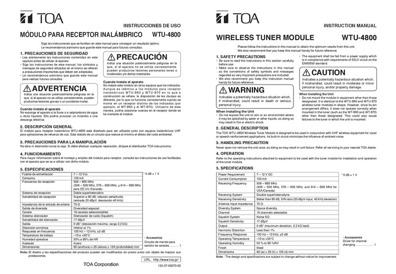
Toa WTU-4800 User manual

Toa

Toa WTU-4800 User manual

Toa WT-740U User manual

Toa

Toa WT-740U User manual

Toa IR-802T User manual

Toa

Toa IR-802T User manual

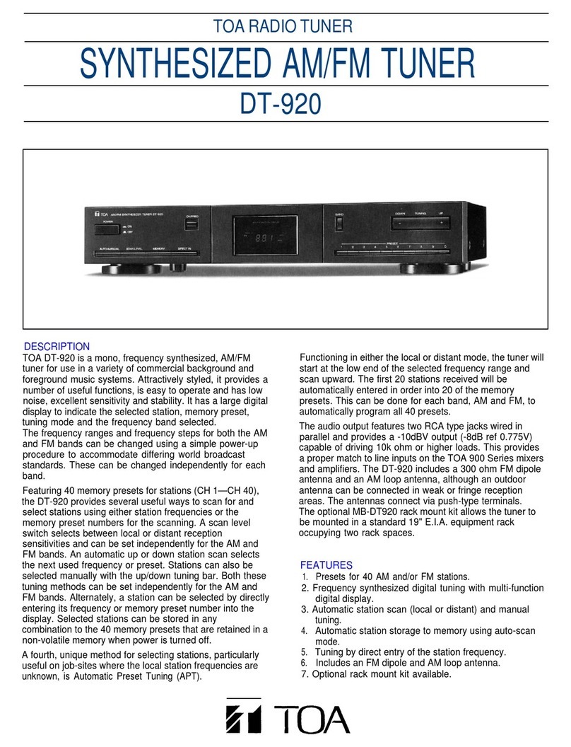
Toa DT-920 User manual

Toa

Toa DT-920 User manual

Toa WT-770 User manual

Toa

Toa WT-770 User manual

Toa DT-940UL User manual

Toa

Toa DT-940UL User manual

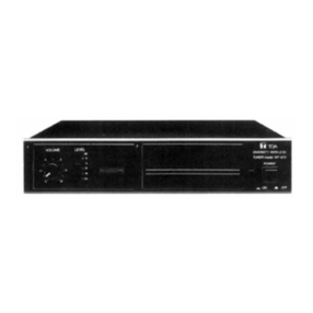
Toa DT-900 User manual

Toa

Toa DT-900 User manual

Toa WT-5800 User manual

Toa

Toa WT-5800 User manual

Toa WT-5810 User manual

Toa

Toa WT-5810 User manual

Toa WT-5800 User manual

Toa

Toa WT-5800 User manual

Toa Scout WT-4810 User manual

Toa

Toa Scout WT-4810 User manual

Toa WT-870 User manual

Toa

Toa WT-870 User manual

Toa WT-4820 User manual

Toa

Toa WT-4820 User manual

Toa WT-781 User manual

Toa

Toa WT-781 User manual

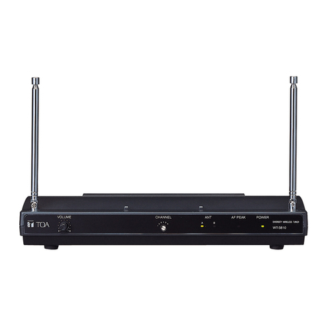
Toa WT-3810 User manual

Toa

Toa WT-3810 User manual

Toa Scout WT-4810 User manual

Toa

Toa Scout WT-4810 User manual

Toa IR-702T User manual

Toa

Toa IR-702T User manual

Toa WT-4800 User manual

Toa

Toa WT-4800 User manual

Popular Tuner manuals by other brands

Palstar AT2K owner's manual

Palstar

Palstar AT2K owner's manual

Kenwood KT-3050 instruction manual

Kenwood

Kenwood KT-3050 instruction manual

Pyle PPDLT2 instructions

Pyle

Pyle PPDLT2 instructions

Comm-Tec ProTUNE TXT user manual

Comm-Tec

Comm-Tec ProTUNE TXT user manual

Realistic TM-152 owner's manual

Realistic

Realistic TM-152 owner's manual

Kenwood Z-838W troubleshooting guide

Kenwood

Kenwood Z-838W troubleshooting guide

Daiwa CNW-518 instruction manual

Daiwa

Daiwa CNW-518 instruction manual

Snark SN-3 instruction manual

Snark

Snark SN-3 instruction manual

Rotel RT-320 operating manual

Rotel

Rotel RT-320 operating manual

Sony hmd-m11 Service manual

Sony

Sony hmd-m11 Service manual

NAD 4020A Specifications

NAD

NAD 4020A Specifications

Xantech XDT77 owner's manual

Xantech

Xantech XDT77 owner's manual

Onkyo T-4070 instruction manual

Onkyo

Onkyo T-4070 instruction manual

Siemens RH 180 Service manual

Siemens

Siemens RH 180 Service manual

Technics ST-8055 Service manual

Technics

Technics ST-8055 Service manual

Mat-Tuner mAT-Y200 instructions

Mat-Tuner

Mat-Tuner mAT-Y200 instructions

Technics ST-HD51 Service manual

Technics

Technics ST-HD51 Service manual

Onkyo T-4711 instruction manual

Onkyo

Onkyo T-4711 instruction manual

manuals.online logo
manuals.online logoBrands
  • About & Mission
  • Contact us
  • Privacy Policy
  • Terms and Conditions

Copyright 2025 Manuals.Online. All Rights Reserved.