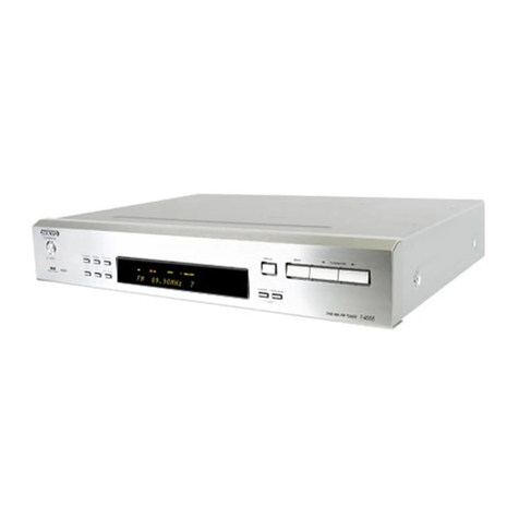
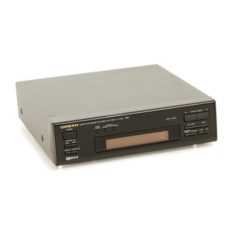
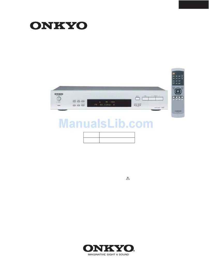
Onkyo T-4070 User manual

E
n
Network Tuner
T-4070
Instruction Manual
Thank you for purchasing an Onkyo Network Tuner.
Please read this manual thoroughly before making
connections and plugging in the unit.
Following the instructions in this manual will enable
you to obtain optimum performance and listening
enjoyment from your new Tuner.
Please retain this manual for future reference.
Contents
Introduction ..................................En-2
Connections.............................. En-10
Enjoying Audio Sources...... En-16
Appendix
Troubleshooting..................... En-37
Specifications ......................... En-39

En-2
Important Safety Instructions
1. Read these instructions.
2. Keep these instructions.
3. Heed all warnings.
4. Follow all instructions.
5. Do not use this apparatus near water.
6. Clean only with dry cloth.
7. Do not block any ventilation openings. Install in
accordance with the manufacturer’s instructions.
8. Do not install near any heat sources such as
radiators, heat registers, stoves, or other apparatus
(including amplifiers) that produce heat.
9. Do not defeat the safety purpose of the polarized or
grounding-type plug. A polarized plug has two
blades with one wider than the other. A grounding
type plug has two blades and a third grounding
prong. The wide blade or the third prong are
provided for your safety. If the provided plug does
not fit into your outlet, consult an electrician for
replacement of the obsolete outlet.
10. Protect the power cord from being walked on or
pinched particularly at plugs, convenience
receptacles, and the point where they exit from the
apparatus.
11. Only use attachments/accessories specified by the
manufacturer.
12.
Use only with the cart,
stand, tripod, bracket, or
table specified by the
manufacturer, or sold
with the apparatus. When
a cart is used, use caution
when moving the cart/
apparatus combination to
avoid injury from tip-over.
13. Unplug this apparatus during lightning storms or
when unused for long periods of time.
14. Refer all servicing to qualified service personnel.
Servicing is required when the apparatus has been
damaged in any way, such as power-supply cord or
plug is damaged, liquid has been spilled or objects
have fallen into the apparatus, the apparatus has
been exposed to rain or moisture, does not operate
normally, or has been dropped.
15. Damage Requiring Service
Unplug the apparatus from the wall outlet and refer
servicing to qualified service personnel under the
following conditions:
A. When the power-supply cord or plug is dam-
aged,
B. If liquid has been spilled, or objects have fallen
into the apparatus,
C. If the apparatus has been exposed to rain or
water,
D. If the apparatus does not operate normally by
following the operating instructions. Adjust only
those controls that are covered by the operating
instructions as an improper adjustment of other
controls may result in damage and will often
require extensive work by a qualified technician
to restore the apparatus to its normal operation,
E. If the apparatus has been dropped or damaged in
any way, and
F. When the apparatus exhibits a distinct change in
performance this indicates a need for service.
16. Object and Liquid Entry
Never push objects of any kind into the apparatus
through openings as they may touch dangerous
voltage points or short-out parts that could result in
a fire or electric shock.
The apparatus shall not be exposed to dripping or
splashing and no objects filled with liquids, such as
vases shall be placed on the apparatus.
Don’t put candles or other burning objects on top of
this unit.
17. Batteries
Always consider the environmental issues and
follow local regulations when disposing of
batteries.
18. If you install the apparatus in a built-in installation,
such as a bookcase or rack, ensure that there is
adequate ventilation.
Leave 20 cm (8") of free space at the top and sides
and 10 cm (4") at the rear. The rear edge of the shelf
or board above the apparatus shall be set 10 cm (4")
away from the rear panel or wall, creating a flue-
like gap for warm air to escape.
WARNING:
TO REDUCE THE RISK OF FIRE OR ELECTRIC
SHOCK, DO NOT EXPOSE THIS APPARATUS
TO RAIN OR MOISTURE.
CAUTION:
TO REDUCE THE RISK OF ELECTRIC SHOCK,
DO NOT REMOVE COVER (OR BACK). NO
USER-SERVICEABLE PARTS INSIDE. REFER
SERVICING TO QUALIFIED SERVICE
PERSONNEL.
The lightning flash with arrowhead symbol, within an
equilateral triangle, is intended to alert the user to the
presence of uninsulated “dangerous voltage” within
the product’s enclosure that may be of sufficient
magnitude to constitute a risk of electric shock to
persons.
The exclamation point within an equilateral triangle is
intended to alert the user to the presence of important
operating and maintenance (servicing) instructions in
the literature accompanying the appliance.
WARNING
RISK OF ELECTRIC SHOCK
DO NOT OPEN
RISQUE DE CHOC ELECTRIQUE
NE PASOUVRIR
AVIS
PORTABLE CART WARNING
S3125A

En-3
Precautions
1. Recording Copyright—Unless it’s for personal
use only, recording copyrighted material is illegal
without the permission of the copyright holder.
2. AC Fuse—The AC fuse inside the unit is not user-
serviceable. If you cannot turn on the unit, contact
your Onkyo dealer.
3. Care—Occasionally you should dust the unit all
over with a soft cloth. For stubborn stains, use a soft
cloth dampened with a weak solution of mild
detergent and water. Dry the unit immediately
afterwards with a clean cloth. Don’t use abrasive
cloths, thinners, alcohol, or other chemical solvents,
because they may damage the finish or remove the
panel lettering.
4. Power
WARNING
BEFORE PLUGGING IN THE UNIT FOR THE
FIRST TIME, READ THE FOLLOWING
SECTION CAREFULLY.
AC outlet voltages vary from country to country.
Make sure that the voltage in your area meets the
voltage requirements printed on the unit’s rear panel
(e.g., AC 230 V, 50 Hz or AC 120 V, 60 Hz).
The power cord plug is used to disconnect this unit
from the AC power source. Make sure that the plug
is readily operable (easily accessible) at all times.
For models with [POWER] button, or with both
[POWER] and [ON/STANDBY] buttons: Pressing
the [POWER] button to select OFF mode does not
fully disconnect from the mains.
If you do not intend to use the unit for an extended
period, remove the power cord from the AC outlet.
For models with [ON/STANDBY] button only:
Pressing the [ON/STANDBY] button to select
Standby mode does not fully disconnect from the
mains.
If you do not intend to use the unit for an extended
period, remove the power cord from the AC outlet.
5. Preventing Hearing Loss
Caution
Excessive sound pressure from earphones and
headphones can cause hearing loss.
6. Batteries and Heat Exposure
Warning
Batteries (battery pack or batteries installed) shall
not be exposed to excessive heat as sunshine, fire or
the like.
7. Never Touch this Unit with Wet Hands—Never
handle this unit or its power cord while your hands
are wet or damp. If water or any other liquid gets
inside this unit, have it checked by your Onkyo
dealer.
8. Handling Notes
• If you need to transport this unit, use the original
packaging to pack it how it was when you
originally bought it.
• Do not leave rubber or plastic items on this unit
for a long time, because they may leave marks on
the case.
• This unit’s top and rear panels may get warm
after prolonged use. This is normal.
• If you do not use this unit for a long time, it may
not work properly the next time you turn it on, so
be sure to use it occasionally.
For British models
Replacement and mounting of an AC plug on the power
supply cord of this unit should be performed only by
qualified service personnel.
IMPORTANT
The wires in the mains lead are coloured in accordance
with the following code:
Blue: Neutral
Brown: Live
As the colours of the wires in the mains lead of this
apparatus may not correspond with the coloured
markings identifying the terminals in your plug,
proceed as follows:
The wire which is coloured blue must be connected to
the terminal which is marked with the letter N or
coloured black.
The wire which is coloured brown must be connected to
the terminal which is marked with the letter L or
coloured red.
IMPORTANT
The plug is fitted with an appropriate fuse. If the fuse
needs to be replaced, the replacement fuse must
approved by ASTA or BSI to BS1362 and have the
same ampere rating as that indicated on the plug. Check
for the ASTA mark or the BSI mark on the body of the
fuse.
If the power cord’s plug is not suitable for your socket
outlets, cut it off and fit a suitable plug. Fit a suitable
fuse in the plug.
For European Models
Declaration of Conformity
We, ONKYO EUROPE
ELECTRONICS GmbH
LIEGNITZERSTRASSE 6,
82194 GROEBENZELL,
GERMANY
GROEBENZELL, GERMANY
ONKYO EUROPE ELECTRONICS GmbH
K. MIYAGI
declare in own responsibility, that the ONKYO product
described in this instruction manual is in compliance with the
corresponding technical standards such as EN60065,
EN55013, EN55020 and EN61000-3-2, -3-3.
En-4
Features
❑Clean Design Aluminum Front Panel
❑Network Capability
• Internet Radio
• DLNA (Digital Living Network Alliance)
❑iPod/iPhone*1 Digital Direct Connection via
USB
❑USB Mass-storage Class Device Compatible
USB
❑
Music Optimizer
*2
for Compressed Digital
Music Files
❑
AirPlay
*1
❑
Separate Wolfson DACs (WM8742) for L/R
Channels
❑
3 Digital Outputs (Optical, Coaxial and AES/
EBU)
❑
DIDRC
*3
(Dynamic Intermodulation
Distortion Reduction Circuitry)
❑Gold Plated Terminals
❑AM/FM 40 Presets
❑
DAB/DAB+
❑RDS (PS/PTY/RT/TP)
❑Anti-vibration Oval Chassis
❑(Remote Interactive) capable
❑Display Dimmer (Normal/Dim/Dimmer)
❑Auto Standby Function
*1
AirPlay, the AirPlay logo, iPad, iPhone, iPod, iPod classic, iPod
nano, iPod shuffle, and iPod touch are trademarks of Apple Inc.,
registered in the U.S. and other countries.
“Made for iPod” and “Made for iPhone” mean that an electronic
accessory has been designed to connect specifically to iPod or
iPhone, respectively, and has been certified by the developer to
meet Apple performance standards.
Apple is not responsible for the operation of this device or its
compliance with safety and regulatory standards.
Please note that the use of this accessory with iPod or iPhone
may affect wireless performance.
*2
Music Optimizer™ is a trademark of Onkyo Corporation.
*3
DIDRC and DIDRC logo are registered trademarks of Onkyo
Corporation.

En-5
Contents
Important Safety Instructions............................ 2
Precautions......................................................... 3
Features ............................................................. 4
Supplied Accessories ........................................ 6
Installing the Batteries............................................... 6
Aiming the Remote Controller.................................. 6
Getting to Know the Tuner ................................ 7
Front Panel ................................................................ 7
Rear Panel ................................................................. 8
Display ...................................................................... 8
Remote Controller..................................................... 9
Connecting Antennas ...................................... 10
Connecting the FM Antenna ................................... 10
Connecting the AM Loop Antenna ......................... 10
Connecting the DAB Antenna ................................ 11
Connecting Your Components........................ 12
Before Making Any Connections............................ 12
Cable and Jacks ....................................................... 12
About Balanced Output (AES/EBU Jack) .............. 13
Connecting to an Amplifier..................................... 13
Connecting Onkyo Components....................... 14
Connecting the Power Cord .................................... 15
Turning On and Standby ......................................... 15
Listening to the Radio...................................... 16
Listening to AM/FM Stations ................................. 16
Listening to DAB Digital Radio ............................. 19
Using RDS .............................................................. 21
Using the USB/Network Device....................... 23
Connecting the iPod/iPhone Directly
to the USB Port ..................................................... 23
Using the AirPlay .................................................... 24
Playing the USB Device.......................................... 25
Listening to the Internet Radio................................ 26
Playing Music Files on a Server.............................. 27
Remote Playback..................................................... 28
Network/USB Features..................................... 29
Connecting to the Network ..................................... 29
Network Requirements............................................ 29
Server Requirements ............................................... 29
USB Device Requirements ..................................... 30
Supported Audio File Formats ................................ 30
About DLNA........................................................... 30
Advanced Setup ............................................... 31
Setting the Display Brightness ................................ 31
Changing the Advanced Setup Settings .................. 31
Advanced Setup Menu ............................................ 32
Firmware Update .............................................. 34
Updating the Firmware via Network....................... 34
Updating the Firmware via USB............................. 35
Troubleshooting ...............................................37
Power.......................................................................37
Audio .......................................................................37
Tuner........................................................................37
Remote Controller ...................................................37
Music Server and Internet Radio .............................37
AirPlay.....................................................................37
USB Device Playback .............................................38
Others ......................................................................38
Specifications ...................................................39

En-6
Supplied Accessories
Make sure you have the following accessories:
Remote controller (RC-831T) and two batteries (AAA/R03)
Audio cable
cable
To use , T-4070 must be connected with an cable.
Indoor FM antenna
AM loop antenna
DAB antenna
Power cord
* In catalogs and on packaging, the letter at the end of the
product name indicates the color. Specifications and
operation are the same regardless of color.
Notes:
• If the remote controller doesn’t work reliably, try
replacing the batteries.
• Don’t mix new and old batteries or different types of
batteries.
• If you intend not to use the remote controller for a long
time, remove the batteries to prevent damage from
leakage or corrosion.
• Expired batteries should be removed as soon as
possible to prevent damage from leakage or corrosion.
When using the remote controller, point it toward the
tuner’s remote control sensor, as shown below.
Installing the Batteries
Aiming the Remote Controller
T-4070
30°
30°
Remote control sensor
Approx. 5 m (16 ft.)

En-7
Getting to Know the Tuner
For detailed information, see the pages in parentheses.
aON/STANDBY button (15, 35, 36, 37)
bTUNING /, PRESET /, /
buttons (16, 19, 22, 24, 28, 31)
cINPUT button (16, 19, 23)
dDISPLAY button (19, 23, 25)
eRT/PTY/TP button (22)
fMEMORY/MENU button (17, 25, 28)
gTUNING MODE/ /button (16, 17, 20, 37)
hSETUP button (18, 19, 20, 24, 31, 34)
iENTER button (17, 19, 20, 24)
jRETURN button (23, 27)
kUSB port (23, 25)
Front Panel
a
9
3
458
7
2
6jk

En-8
Getting to Know the Tuner—Continued
For detailed information, see the pages in parentheses.
aAUDIO OUTPUT jacks (12, 13)
bFM ANTENNA jack and AM ANTENNA
terminal and DAB ANTENNA jack (10, 11)
cREMOTE CONTROL jack (12, 14)
d
DIGITAL OUT COAXIAL and OPTICAL and
AES/EBU jacks
(12, 13)
eETHERNET port (29)
fAC INLET terminal (15)
See “Connecting Antennas”, “Connecting Your
Components” for connection (pages 10 to 15).
For detailed information, see the pages in parentheses.
aM.Opt indicator
b, indicators
cMessage area
dTuning indicators
• RDS indicator (21)
• AUTO indicator (16)
• TUNED indicator (16)
• FM STEREO indicator (16)
eNET indicator (26)
fUSB indicator (23)
gSLEEP indicator (24)
Rear Panel
125
4
36
Display
21 34
567

En-9
Getting to Know the Tuner—Continued
For detailed information, see the pages in parentheses.
abutton (15)
bDIMMER button (31)
cDISPLAY button (19, 23, 25)
dINPUT SELECTOR buttons (16, 19, 23)
eSHUFFL button (23, 24, 25)
fControl buttons (17, 23, 25, 28)
gArrow []/[]/[]/[] and ENTER buttons
(16, 19, 23, 31, 34)
hSETUP button (18, 19, 20, 24, 31, 34)
iNumber buttons (17)
jD.TUN button (17, 18)
kMODE button (16, 23)
lMENU button (25, 26)
mREPEAT button (23, 24, 25)
nRETURN button (19, 20, 23, 27)
Remote Controller
1
2
3
4
5
6
7
8
9
j
k
l
m
n

En-10
Connecting Antennas
This section explains how to connect the supplied
FM antenna, AM loop antenna, and DAB antenna.
The tuner won’t pick up any radio signals if no antenna
is connected, so you must connect the antenna to use the
tuner.
The supplied FM antenna is for indoor use only.
1Attach the FM antenna, as shown.
Once your tuner is ready for use, you’ll need to
tune into an FM radio station and adjust the
position of the FM antenna to achieve the best
possible reception.
2Use thumbtacks or something similar to fix
the FM antenna into position.
Caution: Be careful that you don’t injure yourself when
using thumbtacks.
If you cannot achieve good reception with the supplied
FM antenna, try using a commercially available outdoor
FM antenna instead.
The supplied AM loop antenna is for indoor use only.
1Assemble the AM loop antenna, inserting
the tabs into the base, as shown.
2Connect both wires of the AM loop antenna
to the AM push terminals, as shown.
(The antenna’s wires are not polarity sensitive, so
they can be connected either way around).
Make sure that the wires are attached securely and
that the push terminals are gripping the bare wires,
not the insulation.
Once the your tuner is ready for use, you’ll need to
tune into an AM radio station and adjust the
position of the AM antenna to achieve the best
possible reception.
Keep the antenna as far away as possible from your
tuner, TV, speaker cables, and power cords.
If you cannot achieve good reception with the supplied
AM loop antenna, try using it with a commercially
available outdoor AM antenna.
Connecting the FM Antenna
FM antenna jack
AM antenna
push terminals
DAB antenna jack
Insert the plug fully
into the jack.
Thumbtacks, etc.
Connecting the AM Loop Antenna
Push Release
Insert wire

En-11
Connecting Antennas—Continued
1Screw the supplied DAB antenna’s plug
onto the DAB ANTENNA jack.
Once your tuner is ready for use, you’ll need to
tune into a DAB station and adjust the position of
the DAB antenna to achieve the best possible
reception.
2Use thumbtacks or something similar to fix
the DAB antenna into position.
Connecting the DAB Antenna

En-12
Connecting Your Components
• Refer to the instructions that came with the component you are connecting.
• Do not plug in the power cord until all other connections are complete.
• Do not bind audio cables with power cords and speaker cables.
Doing so may adversely affect the sound quality.
• To prevent interference, keep power cords and speaker cables as far away as
possible from the antennas.
• Push each plug in all the way to make a good connection
(loose connections can cause noise or malfunctions).
Before Making Any Connections
Cable and Jacks
Balanced AES/EBU This is a professional digital audio interface.
Balanced AES/EBU cables are used for better noise
immunity and longer cable runs.
The maximum sampling rate for PCM output is
96kHz/24bit, 2ch.
Optical digital audio Optical digital connections allow you to enjoy digital
sound such as PCM. The maximum sampling rate for
PCM output is 96kHz/24bit, 2ch.
Coaxial digital audio
Coaxial digital connections allow you to enjoy digital
sound such as PCM. The maximum sampling rate for
PCM output is 96kHz/24bit, 2ch.
Analog audio (RCA)
Analog audio connections (RCA) carry analog audio.
USB The network tuner supports high-speed USB 2.0.
You can connect USB memory or iPod/iPhone.
To use (Remote Interactive), you need to connect
your Onkyo AV components with an cable.
Right!
Wrong!
Orange
Red White

En-13
Connecting Your Components—Continued
The tuner’s balanced AES/EBU jack is wired as shown
Plugging the AES/EBU cable
Match the pins and insert the jack until you hear a
“click.” Make sure that the jack is locked by lightly
pulling the connection cable.
Unplugging the AES/EBU cable
Pull out the connection cable while holding down the
button.
Analog Connection
Use the supplied audio cable to connect the T-4070’s
AUDIO OUTPUT L/R jacks to the LINE IN jacks on
your amplifier, as shown.
Digital (Optical or Coaxial) Connection
Use the digital audio cable to connect the T-4070’s
DIGITAL COAXIAL/OPTICAL jacks to the
DIGITAL IN jacks on your amplifier, as shown.
Digital (AES/EBU) Connection
Use the balanced AES/EBU cable to connect the
T-4070’s DIGITAL AES/EBU jacks to the
AES/EBU IN jacks on your amplifier, as shown.
About Balanced Output (AES/EBU Jack)
Connecting to an Amplifier
Push
T-4070
Supplied audio cable
Amplifier
T-4070
Connect either of them.
Amplifier
T-4070
Balanced AES/EBU cable
Amplifier

En-14
Connecting Your Components—Continued
Connection
To use the system functions, use the supplied
cable to make an connection (see the next column).
Note:
• If the T-4070 is used with another Onkyo component,
such as the A-9070, refer to its instruction manual as
well.
If you connect the T-4070 to another Onkyo -capable
component with the supplied cable and audio cable,
you can use the following system functions. cables
are special cables solely for use with Onkyo products.
Auto Power On
When you turn on the T-4070, your Onkyo amplifier will
turn on automatically. (The amplifier’s POWER switch
must be set to ON for this to work.)
Direct Change
When you select a radio preset or change the band (AM,
FM, DAB), your Onkyo amplifier will automatically
select the T-4070 as the input source.
Remote Control Operation
You can control the T-4070 by using your Onkyo
amplifier’s remote controller. See the amplifier’s
instruction manual for details.
With (Remote Interactive), you can control your
-capable Onkyo CD player, T-4070, and so on with
your amp’s remote controller.
Notes:
• Push each plug in all the way to make a good
connection.
• Use only dedicated cables for connections.
cables are supplied with Onkyo tuners and players
(DVD, CD, etc.).
• Some components, including the T-4070, have two
jacks. They’re both the same, so use either one.
•jacks should be connected only to Onkyo
components.
• Connecting them to another manufacturer’s
component may cause a malfunction.
• Some components may not support all functions.
See the manuals supplied with your other Onkyo
components for more information.
Connecting Onkyo Components
T-4070
Supplied cable
Amplifier
T-4070
Onkyo amplifier
(A-9070), etc.
Onkyo CD player
(C-7070), etc.
jack
jack

En-15
Connecting Your Components—Continued
1Connect all of your speakers and AV
components.
2Connect the supplied power cord to the
network tuner’s AC INLET.
3Plug the power cord into an AC wall outlet.
1Press the [ON/STANDBY] button.
Alternatively, press the remote controller’s
[] button.
The tuner comes on, and the display lights up.
To turn the tuner off, press the [ON/STANDBY]
button, or press the remote controller’s [] button. The
tuner will enter Standby mode.
Connecting the Power Cord
Turning On and Standby
AC INLET
To an AC wall outlet
(Plug type varies from
country to country.)
Supplied
power cord

En-16
Listening to the Radio
With the built-in tuner, you can enjoy AM and FM radio
stations.
1Use the tuner’s [INPUT] button, or the
remote controller’s [TUNER] button to
select AM or FM.
In this example, FM has been selected.
(Actual display depends on the country.)
2Press the [TUNING MODE] button or the
remote controller’s [MODE] button so that
the AUTO indicator appears or disappears
from the display.
Auto Tuning
To activate this mode, press the [TUNING MODE]
button to turn on the “AUTO” indicator. In this
mode, you will receive the broadcast in stereo
sound.
Manual Tuning
To activate this mode, press the [TUNING MODE]
button to turn off the “AUTO” indicator. In this
mode, you will receive the broadcast in monaural
sound.
3Press the TUNING [] or [] button.
You can also use the remote controller’s arrow
[]/[] buttons to tune the radio.
Auto Tuning
Searching stops when a station is found.
Manual Tuning
The frequency stops changing when you release
the button.
Press the buttons repeatedly to change the
frequency one step at a time.
The frequency changes in 0.05 MHz steps for FM, and
9kHz (or 10 kHz) steps for AM.
When tuned to a station, the TUNED indicator appears.
When tuned to a stereo FM station, the FM STEREO
indicator also appears.
Tuning to Weak FM Stereo Stations
If the signal from a stereo FM station is weak, it may be
impossible to get good reception. In this case, switch to
Manual Tuning mode and listen to the station in mono.
Listening to AM/FM Stations
,
Band Frequency
AUTO indicator
TUNED FM STEREO

En-17
Listening to the Radio—Continued
■Tuning into Stations by Frequency
You can tune to AM and FM stations directly by entering
the appropriate frequency.
1
Press the remote controller’s [D.TUN] button.
(Actual display depends on the country.)
2Within 8 seconds, use the number buttons
to enter the frequency of the radio station.
For example, to tune to 87.50 (FM), press 8, 7, 5, 0.
Presetting AM/FM Stations
You can store up to 40 of your favorite AM/FM radio
stations as presets.
Presetting FM/AM stations is performed by the tuner.
1Tune to the AM/FM station that you want to
store as a preset.
2Press the [MEMORY] button.
The preset number flashes.
(Actual display depends on the country.)
3While the preset number flashes (about 8
seconds), use the PRESET []/[] buttons
to select a preset from 1 through 40.
4Press the [MEMORY] button again to store
the station or channel.
The station or channel is stored and the preset
number stops flashing.
Repeat this procedure for all of your favorite AM/
FM radio stations.
■Selecting Presets
To select a preset, use the number buttons on
the remote controller, the remote controller’s
arrow []/[] buttons or the tuner’s
PRESET []/[] buttons.
■Deleting Presets
1Select the preset that you want to delete.
See the previous section.
2While holding down the [MEMORY] button,
press the [TUNING MODE] button.
The preset is deleted and its number disappears
from the display.
Number buttons
,
,,,,
,
Number
buttons

En-18
Listening to the Radio—Continued
■Name Edit
You can enter a custom name for radio preset for easy
identification. When entered, the custom name will
appear on the display.
The custom name is edited using the character input
screen.
1Tune to the station of the preset number for
which you want to edit the name, and then
press the [SETUP] button.
2Use the arrow []/[] button to select
“1. Hardware Setup,” and then press
[ENTER].
3Use the arrow []/[] button to select
“Name Edit,” and then press [ENTER].
4Use the arrow []/[]/[]/[] button to
select a character, and then press [ENTER].
Repeat this step to enter up to 10 characters.
5When you’ve finished editing the name and
want to store it, be sure to use the arrow
[]/[]/[]/[] button to select “OK” and
then press [ENTER]. If you fail to do this,
the name won’t be saved.
• Characters are categorized into two groups: character
set 1 primarily for lower case letters, and character set
2 primarily for upper case letters.
You can select characters in each character set by
pressing the []/[] buttons.
Press the []/[] buttons to select a character to input,
and then press the [ENTER] button to confirm.
If you do not find a character that you want to select in
the currently-displayed character set, press the []/
[] buttons to display string “Shift BS OK”, use
the []/[] buttons to select “Shift”, and then press
the [ENTER] button to display the other character set.
• The following table shows available characters.
The meaning of commands other than alphabetical
characters, numbers and symbols is as follows:
Space:
Enters a space character.
Shift*1:
Switches the displayed character.
(Left)/(Right):
Select these to move the cursor within the Name
input area.
BS (Back Space)*2:
Deletes the character to the left of the cursor.
OK:
Specifies that the entry is complete.
Tips:
*1 You can also perform this on the remote
controller by using [DIMMER].
*2 Press [D.TUN] button to clear all characters you
entered.
Notes:
• This procedure can also be performed on the tuner by
using [SETUP], TUNING [
]/[
], PRESET [
]/[
],
and [ENTER].
• Press [RETURN] to return to the previous menu.

En-19
Listening to the Radio—Continued
With the built-in tuner, you can enjoy DAB digital radio.
1Press the tuner’s [INPUT] button, or the
remote controller’s [TUNER] button to
select “DAB”.
When tuned into a DAB station, the station name
will be displayed.
2Use the TUNING []/[] buttons to select
the DAB stations.
You can also use the remote controller’s arrow
[]/[] buttons to selected DAB stations.
Selecting DAB for the Very First Time
The very first time you select DAB, the Auto Tuning
function automatically scans the DAB Band III for the
multiplexes (i.e., stations) available in your area.
Once the scanning process is complete, the first station
that was detected is selected.
Using the Scan Function Manually
1Press the [SETUP] button.
2Use the arrow []/[] button to select
“1.Hardware Setup” and then press
[ENTER].
3Use the arrow []/[] button to select
“1.DAB Scan?” and then press [ENTER].
4Use the arrow []/[] button to select “WW”
or “UK”, (see “DAB Scan?” on page 20),
and then press [ENTER] to stat Auto Tuning
function.
To cancel Auto Tuning, press the [ENTER] button.
If no station is detected after scanning, “No
Station” appears on the display.
Notes:
• This procedure can also be performed on the receiver
by using [SETUP], TUNING []/[], PRESET []/
[], and [ENTER].
• Press [RETURN] to return to the previous step.
Displaying DAB Radio Information
Press the [DISPLAY] button repeatedly to display more
information about the selected DAB station.
1. DLS (Dynamic Label Segment)
When tuned to a station that’s broadcasting DLS text
data, the text will scroll across the display.
Listening to DAB Digital Radio
,,,,

En-20
Listening to the Radio—Continued
2. Program Type
Displays the type of program.
3. Bit Rate and Audio Mode
Displays the station’s bit rate and audio mode
(stereo, mono, or joint stereo).
4. Signal Quality
Displays the signal quality.
0–59: Poor reception
60–79: Good reception
80–100: Excellent reception
5. Multiplex Name
Displays the name of the current multiplex.
6. Multiplex Number and Frequency
Displays the number and frequency of the current
multiplex.
DAB Setup
Use the following functions and settings to set up DAB
digital radio.
1Press the [SETUP] button.
2Use the arrow []/[] button to select
“1.Hardware Setup” and then press
[ENTER].
3Use the arrow []/[] button to select the
item you want to set.
The items are explained below.
■DAB Scan?
This setting determines which DAB bands are scanned
by the Auto Tuning function (see page 19).
UK: Band III (11B–12D).
World (default):
Band III (5A–13F) and L-Band (LA–LW).
■DAB DRC?
With the DRC (Dynamic Range Control) setting, you
can reduce the dynamic range of DAB digital radio so
that you can still hear quiet parts even when listening at
low volume levels—ideal for listening to the radio late at
night when you don’t want to disturb anyone.
Use the arrow []/[] buttons to select the following
options, and then press [ENTER].
0(default): DRC off.
1: Large reduction in dynamic range.
1/2: Small reduction in dynamic range.
Notes:
• This procedure can also be performed on the receiver
by using [SETUP], TUNING []/[], PRESET []/
[], and [ENTER].
• Press [RETURN] to return to the previous menu.
DAB Tuning Mode
1Press the [TUNING MODE] button.
2The items toggle in the order of “Alphabet”
“Multiplex” “Active St” each time the
[TUNING MODE] button is pressed.
With this setting, you can sort the available stations
alphabetically, by multiplex, or active stations.
Alphabet (default):
Sort stations alphabetically.
Multiplex: Sort stations by multiplex.
Active St: Sort by active stations. Receivable stations
appear at the top of the list. stations that
cannot be received properly appear at the
bottom of the list.
,,,,
Table of contents
Other Onkyo Tuner manuals

Onkyo
Onkyo T-35 User manual

Onkyo
Onkyo TX-SV727 User manual

Onkyo
Onkyo T-403 User manual

Onkyo
Onkyo T-404 User manual

Onkyo
Onkyo C-HDXM User manual

Onkyo
Onkyo TX-SV424 User manual

Onkyo
Onkyo T-411RDS User manual

Onkyo
Onkyo UP-HT1 - HD Radio Tuner Module User manual

Onkyo
Onkyo T-4711 User manual

Onkyo
Onkyo TX-SV919 User manual

Onkyo
Onkyo T-9090 II User manual

Onkyo
Onkyo T-4355 User manual

Onkyo
Onkyo TX-SV434 User manual

Onkyo
Onkyo TX-NR1000 User manual

Onkyo
Onkyo T-405TX User manual

Onkyo
Onkyo T-405TX User manual

Onkyo
Onkyo T-9090 II User manual

Onkyo
Onkyo TX-SV414 User manual

Onkyo
Onkyo T-405X User manual

Onkyo
Onkyo T-4700 User manual