TODAAIR DIP9526K-H User manual

Manual
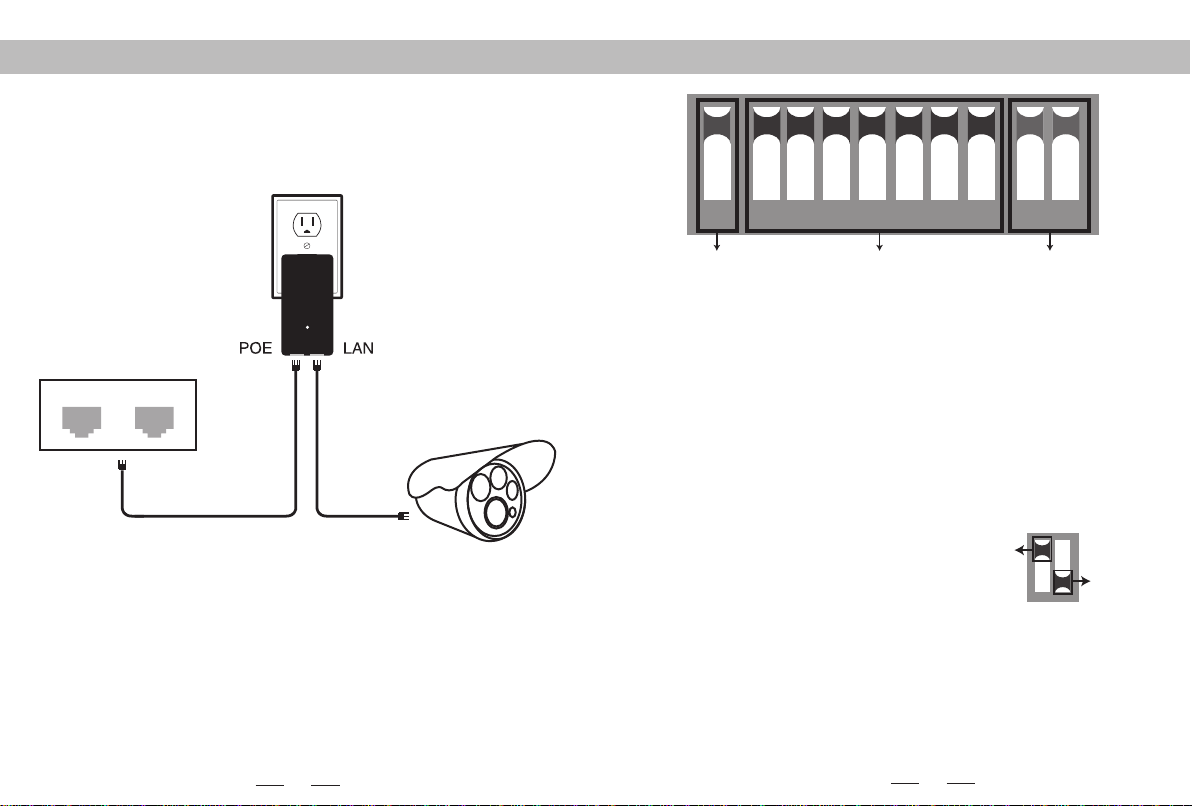
Connecting diagram
POE LAN
POE Port connect with any port of AP
POE LAN port connect with PC(Switch or NVR)
NOTE: 1.Both RJ45 ports(black and yellow) on AP are LAN connections.
2.If you want to enter web page, you need manually bound IP address of PC
3.The PoE power adapter has 3 inputs. One is for the AC cord, and two are
for networking.
4.Please note the PoE adapter and power cord are not designed for outdoor
use and should be used indoors only.
LAN1 LAN2
Gigabit
Product Name: Wireless AP/CPE/Access Point/Bridge
Model: DIP9526K-H
1
Connecting diagram PoE Power
LAN1 LAN2
The bottom of the adapter has two RJ45 connections. One marked POE and one
marked LAN.
Using one CAT5 cable(Network cable) , connect one end to ”LAN” and the other
end to your camera,recorder, PC, etc.
DIP device instructions
1 2 3 4 5 6 7 8 9 10
Working Mode Key Matching Key IP Key
Up
Down
Button 1 changes the mode of the device. UP is access point (AP) mode for use
with your recorder, PC, etc.. DOWN is for use with your camera.
Button 2 through 8 are for matching AP devices together. There are 128 various
combinations that can be made from the 7 keys, which corresponds to 128 different
SSIDs and 128 different segments. The Pages 8-15 below shows all possible
combinations.
Button 9 & 10 are for point to multi-point functionality. To use up to 4 cameras
with one recorder, configure the DIP switches as follows:
1.On the recorder/PC/Switch side, switches 9 and 10 should remain up.
2.On the camera side, select one of 4 configurations for switches 9 and 10:
a.Camera 1: 9 Down and 10 Down
b.Camera 2: 9 Down and 10 Up
c.Camera 3: 9 Up and 10 Down
d.Camera 4: 9 Up and 10 Up
3.You cannot duplicate the switch settings between Cameras for switches 9 & 10 or
you will experience interference, thus the max of 4 points.
Remarks:
1.Turn off the AP power before setting the button.
2.The SSID of DIP type AP defaults is not broadcast, password has been set up and
can be customized.
3. Make sure the IP address of the camera is different from AP
2

4
NOTE:Subnet Mask must be
"255.255.0.0" for IP
"172.19.0.2"
(picture 1)
General
You can get IP settings assigned automatically if your network supports
this capability.Otherwise,you need to ask your network administrator for the
appropriate IP settings.
Obtain an IP address automatically
IP address:
Subnet mask:
Default gateway:
172.19.0.2
255.255.0.0
Obtain DNS server address automatically
Use the following DNS server address:
Preferred DNS server:
Alternate DNS server:
Use the following IP address:
. . .
. . .
. . .
Advanced...
OK Cancel
NOTE:The bound IP address of 5.8G is 172.19.0.2
Subnet mask is 255.255.0.0
Signal power setting
Step 1 Manual disposes static IP address,as it's shown in figure1 (type corespon-
ding device IP address at browser, default password: password)
Down
Down
Down
Down
3
The specific operation for setting management
1 2 3 4 5 6 7 8 9 10
Up:Working mode key Matching key Default
① ② ③
Camera1
Camera2
Transmitter
Receivers
Camera3
Camera4
NOTE: For the point-to-point case, either of the four camera options above is
available. Make sure the working mode key and matching Key are set right.
5.8G:AP 172.19.127.1
172.19.127.5
172.19.127.25.8G:CPE
5.8G:CPE
1 2 3 4 5 6 7 8 9 10
172.19.127.35.8G:CPE
① ② ③
① ② ③
① ② ③
① ② ③
1 2 3 4 5 6 7 8 9 10
172.19.127.45.8G:CPE
1 2 3 45 6 7 8 9 10
1 2 34 5 6 7 8 9 10
…

6
Q1: What should be noted when setting the AP button?
A1: Make sure the power is off.
Q2: How dose the AP work without power supply?
A2: The AP gets the power via the cable. It is called POE. Two cables are needed for
the connection. STP CAT5e cable is strongly recommended for this case.
Q3: How long the POE cable can be?
A3: The length of the cable depends on the power voltage and cable quality. For 24V
power, the length of the cable can be 40 meters, while 10-20 meters for 12V
power.
Q4: Why the signal light does not work after switching the button?
A4: Please turn off the AP power first. It is recommended to do the troubleshooting
test as below. For the transmitter, keep the button from “1” to “10” UP. For the
receiver, keep the button “1” DOWN, and the button from “2” to “10” UP. After
finishing, turn on the power and wait for three minutes. The distance between the
transmitter and the receiver should be more than 2 meters.
1 2 3 4 5 6 7 8 9 10 1 2 3 4 5 6 7 8 9 10
Transmitter Receiver
Q5: Why the local network connection is choppy after the AP installation?
A5: Shoot the trouble with below methods:
1. Change the cable to see if it is a cable problem
2. Change the wireless channel to avoid the signal interference.
Q&A
5
Transmit Power Configuration: The default is the maximum value, the transmit
power should be reduced appropriately when the signal is too strong.
Encryption Configuration: Customized key can be used for security. (The same
key should be set in the transmitter and receiver.)
Distance Configuration: Default value is two kilometers, it should be set according
to practical situation. (The same distance value should be set in the transmitter and
receiver. If not, it will lead to high latency, low bandwidth network connection.)
Country code: In text (manual) mode, the channels are determined by the the
dial-up button. It is automatically selected in other modes.
Step 2 Type the IP address of corresponding AP device in IE browser to get into
the WEP page, the default password is “password”. Signal power can be set after
logging.
Signal power setting
Status
Logout
Transmit Power
Mode
Router Access
Time
Backup / Restore
Update Firmware
Reboot
System
Country code
Country code: Test (Text)
Transmit Power Configuration
Power:
Client Signal Threshold
dBm
Encryption Configuration
Use Custom Key:
Distance Configuration
Distance:
Signal Threshold: (Only for Station)
show
Close
2KM
.............
Save Changes Reset

Q6: How to log in the WEP page?
A6: Set the computer with static IP address as shown in Page 4-5, and type the IP
address of the corresponding device in IE browser.
Q7: After the connection of the AP and NVR, why the IP address of the camera can
be found but no video available on the monitor?
A7: Connect the adapter which links to the NVR with the yellow LAN port of the AP.
Q8: The status of signal light
A8: Red: PWR: The power light. It will work when power is on.
Blue: WLAN: WIFI signal light. It will strobe when working.
LAN1,LAN2: The LAN1/LAN2 light. It will be on when working.
Orange: Wireless signal light from 1st - 4th
1st light on: the signal is too weak.
1st , 2nd lights on: signal is weak.
1st, 2nd, 3rd lights on: the signal is regular.
ONLY the 4th light on: the signal is too strong.
If four lights are on, the signal is in the best condition
Q9:How to reset the device?
A9:Long press the RST button for 6 seconds in the state of power-on.
7
LAN2
1st 2nd 3rd 4th
LAN1WLANPOWER
8
The dial-up code corresponding to the text (manual) mode, the network segment and
frequency can refer to the following table.
Group
No.3
No.4
No.5
No.6
No.7
No.8
No.9
No.10
No.11
No.12
No.13
No.14
No.15
No.16
IP segment
172.19.0.X
172.19.1.X
172.19.2.X
172.19.3.X
172.19.4.X
172.19.5.X
172.19.6.X
172.19.7.X
172.19.8.X
172.19.9.X
172.19.10.X
172.19.11.X
172.19.12.X
172.19.13.X
172.19.14.X
172.19.15.X
Frequency
5180
5200
5220
5240
2-8 Dial
2 3 4 5 6
2 3 4 5 6
23456
2 3 4 5 6
2 3 4 5 6
2 3 4 5 6
23456
2 3 4 5 6
23456
2 3 4 5 6
23456
2 3 4 5 6
2 3 4 5 6
2 3 4 5 6
2 3 4 5 6
2 3 4 5 6 7 8
7 8
7 8
7 8
7 8
7 8
7 8
7 8
7 8
7 8
7 8
7 8
7 8
7 8
7 8
7 8
No.1
No.2
Disable for users
Disable for users
Disable for users
Disable for users
Disable for users
Disable for users
Disable for users
Disable for users
Disable for users
Disable for users
Disable for users
Disable for users

9 10
Ps: The shadow marks are the national standard frequencies, and the remaining
frequencies are only for testing. (X is the last IP address)
Group
No.17
No.18
No.19
No.20
No.21
No.22
No.23
No.24
No.25
No.26
No.27
No.28
No.29
No.30
No.31
No.32
IP segment
172.19.16.X
172.19.17.X
172.19.18.X
172.19.19.X
172.19.20.X
172.19.21.X
172.19.22.X
172.19.23.X
172.19.24.X
172.19.25.X
172.19.26.X
172.19.27.X
172.19.28.X
172.19.29.X
172.19.30.X
172.19.31.X
Frequency
5745
5765
5785
5805
5180
5200
5220
5240
2-8 Dial
23456
23456
23456
23456
23456
23456
23456
23456
23456
23456
23456
23456
23456
23456
23456
2 3 4 5 6 7 8
7 8
7 8
7 8
7 8
7 8
7 8
7 8
7 8
7 8
7 8
7 8
7 8
7 8
7 8
7 8
No.33
No.34
No.35
No.36
No.37
No.38
No.39
No.40
No.41
No.42
No.43
No.44
No.45
No.46
No.47
No.48
5745
5765
5785
172.19.32.X
172.19.33.X
172.19.34.X
172.19.35.X
172.19.36.X
172.19.37.X
172.19.38.X
172.19.39.X
172.19.40.X
172.19.41.X
172.19.42.X
172.19.43.X
172.19.44.X
172.19.45.X
172.19.46.X
172.19.47.X
2 3 4 5 6
23456
23456
2 3 4 5 6
2 3 4 5 6
2 3 4 5 6
2 3 4 5 6
2 3 4 5 6
2 3 4 5 6
2 3 4 5 6
23456
2 3 4 5 6
2 3 4 5 6
2 3 4 5 6
23456
2 3 4 5 6 7 8
7 8
7 8
7 8
7 8
7 8
7 8
7 8
7 8
7 8
7 8
7 8
7 8
7 8
7 8
7 8
Group
IP segment
Frequency
2-8 Dial
Ps: The shadow marks are the national standard frequencies, and the remaining
frequencies are only for testing. (X is the last IP address)
Disable for users
Disable for users
Disable for users
Disable for users
Disable for users
Disable for users
Disable for users
Disable for users
Disable for users
Disable for users
Disable for users
Disable for users
Disable for users
Disable for users
Disable for users
Disable for users
Disable for users
Disable for users
Disable for users
Disable for users
Disable for users

11
12
No.49
No.50
No.51
No.52
No.53
No.54
No.55
No.56
No.57
No.58
No.59
No.60
No.61
No.62
No.63
No.64
5805
5180
5200
5220
5240
172.19.48.X
172.19.49.X
172.19.50.X
172.19.51.X
172.19.52.X
172.19.53.X
172.19.54.X
172.19.55.X
172.19.56.X
172.19.57.X
172.19.58.X
172.19.59.X
172.19.60.X
172.19.61.X
172.19.62.X
172.19.63.X
23456
23456
23456
23456
23456
23456
23456
23456
23456
23456
23456
23456
23456
23456
23456
2 3 4 5 6 7 8
7 8
7 8
7 8
7 8
7 8
7 8
7 8
7 8
7 8
7 8
7 8
7 8
7 8
7 8
7 8
No.65
No.66
No.67
No.68
No.69
No.70
No.71
No.72
No.73
No.74
No.75
No.76
No.77
No.78
No.79
No.80
5745
5765
5785
5805
5180
5200
5220
5240
172.19.64.X
172.19.65.X
172.19.66.X
172.19.67.X
172.19.68.X
172.19.69.X
172.19.70.X
172.19.71.X
172.19.72.X
172.19.73.X
172.19.74.X
172.19.75.X
172.19.76.X
172.19.77.X
172.19.78.X
172.19.79.X
2 3 4 5 6
2 3 4 5 6
2 3 4 5 6
23456
23456
2 3 4 5 6
23456
2 3 4 5 6
23456
2 3 4 5 6
2 3 4 5 6
2 3 4 5 6
2 3 4 5 6
2 3 4 5 6
2 3 4 5 6
2 3 4 5 6 7 8
7 8
7 8
7 8
7 8
7 8
7 8
7 8
7 8
7 8
7 8
7 8
7 8
7 8
7 8
7 8
Ps: The shadow marks are the national standard frequencies, and the remaining
frequencies are only for testing. (X is the last IP address)
Ps: The shadow marks are the national standard frequencies, and the remaining
frequencies are only for testing. (X is the last IP address)
Group
IP segment
Frequency
2-8 Dial
Group
IP segment
Frequency
2-8 Dial
Group
IP segment
Frequency
2-8 Dial
Disable for users
Disable for users
Disable for users
Disable for users
Disable for users
Disable for users
Disable for users
Disable for users
Disable for users
Disable for users
Disable for users Disable for users
Disable for users
Disable for users
Disable for users
Disable for users
Disable for users
Disable for users
Disable for users

13 14
No.81
No.82
No.83
No.84
No.85
No.86
No.87
No.88
No.89
No.90
No.91
No.92
No.93
No.94
No.95
No.96
5745
172.19.80.X
172.19.81.X
172.19.82.X
172.19.83.X
172.19.84.X
172.19.85.X
172.19.86.X
172.19.87.X
172.19.88.X
172.19.89.X
172.19.90.X
172.19.91.X
172.19.92.X
172.19.93.X
172.19.94.X
172.19.95.X
23456
23456
23456
23456
23456
23456
23456
23456
23456
23456
23456
23456
23456
23456
23456
2 3 4 5 6 7 8
7 8
7 8
7 8
7 8
7 8
7 8
7 8
7 8
7 8
7 8
7 8
7 8
7 8
7 8
7 8
No.97
No.98
No.99
No.100
No.101
No.102
No.103
No.104
No.105
No.106
No.107
No.108
No.109
No.110
No.111
No.112
5765
5785
5805
5180
5200
5220
5240
172.19.96.X
172.19.97.X
172.19.98.X
172.19.99.X
172.19.100.X
172.19.101.X
172.19.102.X
172.19.103.X
172.19.104.X
172.19.105.X
172.19.106.X
172.19.107.X
172.19.108.X
172.19.109.X
172.19.110.X
172.19.111.X
2 3 4 5 6
23456
2 3 4 5 6
2 3 4 5 6
23456
2 3 4 5 6
23456
2 3 4 5 6
2 3 4 5 6
2 3 4 5 6
2 3 4 5 6
2 3 4 5 6
2 3 4 5 6
2 3 4 5 6
23456
2 3 4 5 6 7 8
7 8
7 8
7 8
7 8
7 8
7 8
7 8
7 8
7 8
7 8
7 8
7 8
7 8
7 8
7 8
Ps: The shadow marks are the national standard frequencies, and the remaining
frequencies are only for testing. (X is the last IP address)
Ps: The shadow marks are the national standard frequencies, and the remaining
frequencies are only for testing. (X is the last IP address)
Group
IP segment
Frequency
2-8 Dial
Group
IP segment
Frequency
2-8 Dial
Disable for users
Disable for users
Disable for users
Disable for users
Disable for users
Disable for users
Disable for users
Disable for users
Disable for users
Disable for users
Disable for users
Disable for users
Disable for users
Disable for users
Disable for users
Disable for users
Disable for users
Disable for users
Disable for users
Disable for users
Disable for users
Disable for users
Disable for users
Disable for users

15
No.113
No.114
No.115
No.116
No.117
No.118
No.119
No.120
No.121
No.122
No.123
No.124
No.125
No.126
No.127
No.128
5745
5765
5785
5805
5180
5200
5220
172.19.112.X
172.19.113.X
172.19.114.X
172.19.115.X
172.19.116.X
172.19.117.X
172.19.118.X
172.19.119.X
172.19.120.X
172.19.121.X
172.19.122.X
172.19.123.X
172.19.124.X
172.19.125.X
172.19.126.X
172.19.127.X
23456
23456
23456
23456
23456
23456
23456
23456
23456
23456
23456
23456
23456
23456
23456
2 3 4 5 6 7 8
7 8
7 8
7 8
7 8
7 8
7 8
7 8
7 8
7 8
7 8
7 8
7 8
7 8
7 8
7 8
Ps: The shadow marks are the national standard frequencies, and the remaining
frequencies are only for testing. (X is the last IP address)
Group
IP segment
Frequency
2-8 Dial
Disable for users
Disable for users
Disable for users
Disable for users
Disable for users
Disable for users
Disable for users
Disable for users
Disable for users

FCC Warning
This device complies with part 15 of the FCC rules. Operation is subject to the following two
conditions: (1) this device may not cause harmful interference, and (2) this device must accept
any inte rference received, including interference that may cause undesired operation.
Changes or modifications not expressly approved by the party responsible for compliance could
void the user's authority to operate the equipment.
NOTE: This equipment has been tested and found to comply with the limits for a Class B digital
device, pursuant to part 15 of the FCC Rules. These limits are designed to provide reasonable
protection against harmful interference in a residential installation. This equipment generates
uses and can radiate radio frequency energy and, if not installed and used in accordance with the
instructions, may cause harmful interference to radio communications. However, there is no
guarantee that interference will not occur in a particular installation. If this equipment does
cause harmful interferenceto radio or television reception, which can be determined by turning
the equipment off and on, the user is encouraged to try to correct the interference by one or
more of the following measures:
-Reorient or relocate the receiving antenna.
- Reorient or relocate the receiving antenna.
- Reorient or relocate the receiving antenna.
- Consult the dealer or an experienced radio/TV technician for help important announcemen
Radiation Exposure Statement
This equipment complies with FCC radiation exposure limits set forth for an uncontrolled
environment. This equipment should be installed and operated with minimum distance 20cm
between the radiator and your body.

ISED Statement
‐English: This device complies with Industry Canada license‐exempt RSS standard(s).
Operation is subject to the following two conditions: (1) This device may not cause interference, a
nd (2) This device must accept any interference, including interference that may cause undesired
operation of the device. The digital apparatus complies with Canadian CAN ICES‐3 (B)/NMB‐3(B).
‐French: Le présentappareilestconforme aux CNR d'Industrie Canada applicables aux appareils
radio exempts de licence. L'exploitationestautorisée aux deux conditions suivantes: (1) l'appareil
ne doit pas produire de brouillage, et (2) l'utilisateur de l'appareildoit accepter tout brouillageradi
oélectriquesubi, mêmesi le brouillageest susceptible d'encompromettre le fonctionnement.
This radio transmitter (ISED certification number: 24002-TODAAIRAC) has been approved by
Industry Canada to operate with the antenna types listed with the maximum permissible gain
indicated. Antenna types not included in this list, having a gain greater than the maximum gain
indicated for that type, are strictly prohibited for use with this device.
Le présent émetteur radio (ISED certification number: 24002-TODAAIRAC) a été approuvé par
Industrie Canada pour fonctionner avec les types d'antenne énumérés ci-dessous et ayant un gain
admissible maximal. Les types d'antenne non inclus dans cette liste, et dont le gain est supérieur
au gain maximal indiqué, sont strictement interdits pour l'exploitation de l'émetteur.
Radiation Exposure Statement
This equipment complies with Canada radiation exposure limits set forth for an uncontrolled
environment. This equipment should be installed and operated with minimum distance 20cm
between the radiator & your body.
Déclaration d'exposition aux radiations
Cet équipement est conforme Canada limites d'exposition aux radiations dans un environnement
non contrôlé. Cet équipement doit être installé et utilisé à distance minimum de 20cm entre le
radiateur et votre corps.
Other TODAAIR Wireless Access Point manuals

Popular Wireless Access Point manuals by other brands


Motorola
Motorola AP-6511 installation guide

Intermec
Intermec 6710 Reference manual

Dell
Dell W-IAP277 installation guide

Gigabyte
Gigabyte GN-A16B user guide

Moxa Technologies
Moxa Technologies Airworks AWK-3131A-M12-RCC user manual

Snap One
Snap One TS-PAMP4-125-V2 Regulatory compliance and safety information

Orinda Networks
Orinda Networks S0-738 user manual

NETGEAR
NETGEAR SSL312 - ProSafe SSL VPN Concentrator 25 Specifications

ORiNG
ORiNG IAP-620 Series Quick installation guide

HPE
HPE Instant On AP22D installation guide

Planet Networking & Communication
Planet Networking & Communication WAP-4036 user manual

Ubiquiti
Ubiquiti UniFi WiFi BaseStationXG UWB-XG-BK quick start guide