Toft Audio Designs ATB series Console User manual

www.toftaudio.com
TABLE OF CONTENTS
Introduction
Power and Audio Connections
Star Grounding
Input Module
Input Module Flow Diagram
Submaster Module
Submaster Module Flow Diagram
Master Section
Master Section Flow Diagram
Overall Flow Diagram
Operational Description
Meter Bridge Option
Digital I/O Option
Technical Specifications
Safety Information
Safety Instructions
Environmental Compliance Statements
Warranty
Registration
Meter Bridge Installation Instructions
1
2
5
6
8
9
11
12
14
15
16
20
21
22
23
23
24
25
26
31

Toft Audio Designs Series ATB Console

www.toftaudio.com
INTRODUCTION
The Toft Audio Series ATB is the creation of Malcolm Toft who was the founder of console man-
ufacturer Trident Audio Developments in 1972. Prior to that he was a recording engineer whose
credits include the David Bowie ‘Space Oddity’ album, three albums with T-Rex and James Tay-
lor’s first album. He was also involved with the mixing of the Beatles ‘Hey Jude’ single at Trident
Recording Studios in 1968. Trident Audio Developments became an acclaimed manufacturer
of recording consoles and artists who have recorded hits on a Trident console include:, Stevie
Wonder, Herbie Hancox, Rod Stewart, Queen, David Bowie and Elton John. More recently, Dire
Straits, Coldplay and Oasis have added their name to the list. Malcolm sold Trident in 1988 but
continued to make consoles under the MTA (Malcolm Toft Associates) banner until just a few
years ago. Radiohead have in fact recorded all of their albums from O.K. Computer onwards on
an MTA console. It is this pedigree that is continued with his new range under the Toft Audio
Designs marque.
The Series ATB is an extremely versatile and sophisticated 8 bus console in a compact frame. It
has been designed with todays DAW user in mind and offers extremely high audio quality and
features never before found in a console in its’ price range. These features include an optional
digital I/O card which provides the eight subgroup sends and returns as either ADAT optical or
firewire and the master left/right outputs as firewire or SPDIF. ASIO drivers are provided as well
as MIDI connectivity to complete the versatility of this option.
In a multi-track studio environment the console will perform both tracking and remix functions
with consumate ease. Because of the channel monitor and direct output facilities, recording
instruments to tape is simple and of very high quality with little outboard equipment being re-
quired. When mixing down, the large number of inputs to the stereo bus (56 on the 16 chan-
nel, 72 on the 24 channel and 88 on the 32 channel) makes the job very easy. The large number
of auxiliary sends (six) also adds to the flexibility.
The Series ATB has also been designed for easy servicing. The console is constructed from
individual circuit boards mounted at right angles to an 8 way front panel. It is therefore only
a matter of minutes to remove any channel board from it’s front panel should a component
need replacing. All active circuitry (i.c.’s etc) are socketed, again to aid servicing. All passive
components (resistors, capacitors etc.) are of conventional types not surface mount which are
difficult to remove and replace. The modules connect to each other via ribbon cables which
ensure maximum reliability and freedom from wiring errors.
Connections to the console are via the rear panel where the cables can be conveniently hidden
from view, which is again a feature normally only found in consoles costing considerably more.
The console is fitted with extremely accurate 12 segment bar graph displays on the groups and
master left/right outputs and high quality illuminated V.U meters operate in parallel with the mas-
ter left/right bargraphs.
By carefully following the installation procedures detailed in the following pages, your Series ATB
console will give years of professional audio quality and reliable service.
1

Toft Audio Designs Series ATB Console
POWER & AUDIO CONNECTIONS
D.C. POWER:
The Series ATB is supplied with a high quality D.C. power supply which should be connected to a
suitable a.c. power source via an earthed cable connected to the 3 pin euro socket at the back of the
power supply.
The supply has been fitted with the highest quality ‘toroidal’ type transformer in order to minimise
stray hum radiation, but the supply should still be located as far away from the console as possible to
avoid any possibility of hum pick -up.
Before connecting to a power socket, make sure that the correct voltage is selected on the rear of
the power supply, either 115 or 230 volts.
Make sure that the supply is placed in a well ventilated area, with at least one rack space between
the supply and other units.
Low voltage D.C is supplied to the console via a circular locking connector. With the power supply
switched off, this should be pushed firmly into the mating socket on the rear of the console located
behind the Master Module. A locking ring makes sure that the cable cannot be accidentally pulled
from the console.
The D.C power connections are as follows:
Pin 1 +17v
Pin 2 Chassis Ground
Pin 3 Electronics Ground
Pin 4 +48V
Pin 5 -17V
Once the power supply has been connected to the console, the correct voltage selected and the
a.c. power applied, the power supply can be switched on. The power supply is fitted with three
red l.e.d’s which indicate that the +17, -17 and +48 voltages are functioning. If for any reason any
of the l.e.d’s fail to illuminate, do not operate the console. Turn the power supply off immediately
and check that the fuses (located inside the unit) are not blown. If any fuse has blown, replace with
one of the same rating and try again. If the fuse has not blown or a replacement fails subsequently,
seek qualified help.
2

www.toftaudio.com
3
AUDIO CONNECTIONS:
Two types of audio connector are provided on the rear of the unit, x-l-r and 1/4” jack.
The mic input x-l-r is female and therefore the microphone lead requires a male plug. The wiring
convention is as follows:
Pin 1 Earth
Pin 2 +(positive phase)
Pin 3 - (negative phase)
Various connections to the console use balanced (stereo) 1/4” jacks and are wired as follows:
Sleeve Earth
Tip +(positive phase)
Ring - (negative phase)
The balanced connections are: Channel ‘LINE’ Input, Channel ‘MON’, Channel ‘DIR O/P, ‘MONITOR
RETURNS’, ‘SUBMASTER OUTPUTS’, ‘MASTER O/P’, ‘AUX MASTERS’, ‘MAIN SPKRS’ and ‘ALT
SPKRS’
The ‘STEREO FX RETURNS’ and ‘2 TRACK RET.’ 1 and 2 utilise a balanced (stereo) jack wired in the
following manner:
Sleeve Earth
Tip Right (unbalanced)
Ring Left (unbalanced)
Various connections to the console are unbalanced (mono) 1/4” jacks and are wired as follows:
Sleeve Earth
Tip + (positive phase)
The unbalanced connections are: Channel ‘DIR O/P’, ‘ALT SPKR’, ‘MAIN SPKR’.
The Channel ‘INSERT’ Sends, ‘SUBGROUP INSERT’ Sends and ‘MASTER INS.’ Sends Utilise 1/4”
stereo jacks wired in the following manner:
Sleeve Earth
Tip Send
Ring Return

Toft Audio Designs Series ATB Console
SERIES ATB REAR PANEL - INPUT SECTION
SERIES ATB REAR PANEL - OUTPUT SECTION
4

www.toftaudio.com
STAR GROUNDING
By connecting equipment together using the ‘star grounding’ principle it is possible to virtually
eliminate hum loops from studio wiring.
Since the system is quite easy to implement, it only requires following a certain procedure that will
soon become second nature. A few moments spent studying this chapter and following the steps
listed below, could pay dividends in the future.
Step 1. Choose a particular piece of equipment that will be made ‘technical’ earth (in most cases
the mixing console is the ideal choice as it is usually the item that everything else is connected to).
Step 2. On all equipment that is connected to the console inputs, connect the earth (sleeve) of
the cable carrying the signal at the console end but not the end that connects to the equipment.
For example, if it is a jack lead, connect the sleeve at the mixer end but not at the equipment end.
The only exception to this should be a microphone as it cannot get an electrical earth by any other
means. The earth should therefore be connected at both ends of a microphone cable.
Step 3. On all equipment that is connected to the console outputs, connect the earth (sleeve) at
the console end but not at the equipment end (input).
Step 4. Connect the chassis or mains earth of all equipment to the same point that the console
chassis and power supply earth are connected to. This point is then known as the ‘technical’ earth
and should be as good as it possibly can be. In many cases this will be the earth of the mains
socket feeding the console, but sometimes better results and freedom from refrigerator clicks
and pops etc. can be achieved by making an independent ‘technical’ earth. In many professional
recording studios this is done by burying a large copper plate at least three feet underground and
connecting the ‘technical’ earth point to it. A less drastic measure is to use the copper pipe of a
radiator as the earth reference as this often runs underground.
It is essential that if a separate technical earth is generated, this is always used as the earth point
for all equipment. Connecting some equipment to mains earth and some to ‘technical’ earth
could result in a shock hazard as it is sometimes possible for a quite high a.c voltage difference to
be generated across the two earth points.
5

Toft Audio Designs Series ATB Console
INPUT MODULE
INPUT MODULE General Description
INPUT MODULE General Description
The Series ATB Input Module is an extremely sophisticated and
flexible channel that can be used for recording, mixing and moni-
toring multi-track recordings. It will accept the signal from a low
impedance balanced microphone, high or low level balanced line
input, or even the output from a musical instrument.
The signal can be shaped via the extremely musical four band
equaliser section that allows precise control over the audio spec-
trum. Boost and cut of 15dB is provided by centre detented
controls and the two sweep frequency ranges overlap to increase
the flexibility of the equaliser section. An 80Hz (high pass) filter
is also incorporated which can be switched in or out of circuit.
The equaliser is extremely useful in both recording and mixing
modes. The equaliser can also be switched from the input chan-
nel to the separate monitor channel incorporated into each input
module.
Six auxiliary sends are provided. Aux 1 is permanently pre-fade
while auxes 3-6 can be switched pre or post the channel fader
Auxes 5-6 can also be selected between the channel or monitor
path, greatly adding to the flexibility of the module.
Each module incorporates a monitor section which is used to
monitor a replay channel from a multi-track recording device.
This is in effect a separate signal path which ultimately feeds the
master remix outputs. By making the equaliser and auxiliary
sends 5-6 available to this path, this becomes an extremely ver-
satile feature of the console. When monitoring the output of a
multi-track recorder or DAW, it is possible to create a monitor mix
with equalisation and reverb effects completely independently
from the channel. These effects would also remain when the
recording is played back through the same monitor section.
When the console is used for mixing purposes, the monitor
section functions as an additional line input return to the stereo
mix busses, again with the ability to route the equalisation and
auxiliary sends 5-6 through the monitor section. This effectively
doubles the number of inputs available on remix. As there are
also eight dedicated stereo effects returns and 8 monitor returns
6

www.toftaudio.com
on the sub group section, at mixdown a 16 channel Series ATB becomes a 56 input mixer whilst a 24
channel becomes a 72 input mixer and a 32 channel becomes an 88 input mixer.
The input channel is provided with a stereo, non destructive after fade listen system (AFL). By de-
pressing this button, it is possible to hear the selected signal in isolation (or mixed with other select-
ed AFL signals). When the AFL button is depressed, the Channel ‘MUTE’ led will illuminate green to
show that AFL has been selected on that channel. When used for normal channel muting purposes,
the ‘MUTE’ led will illuminate red. The AFL signal follows the position of the channel pan control so
that the signal can be monitored with the stereo perspective intact. As it is a monitor function only,
the AFL can be depressed when recording or mixing without it harming the signal path. It is however
possible to change the function of the switch on a channel by channel basis so that the signal be-
comes a mono, pre-fade source (PFL). This is useful if the console is used in a live sound application
where a simple check to see if a channel is ‘live’ is required without having to push up the fader. By
removing the base panel of the mixer and accessing the individual channel pcb’s, it will be possible to
see a pushbutton switch mounted approximately halfway down the circuit board. When the button is
depressed (factory default setting) the signal is in AFL mode. If the button is undepressed, the signal
from that channel will become PFL.
Centre detented pan controls are provided for both the channel and monitor sections for accurate
placement of signals in the stereo spectrum.
The channel path is provided with a green l.e.d which illuminates when the signal reaches -20dB at
the channel output and a red l.e.d which illuminates when the signal reaches +10dB at the channel
output. These are extremely useful features and provide a constant indication that a signal is pres-
ent in the module (green l.e.d), and that signal peak is being reached (red l.e.d).
Routing to the multi-track groups is achieved by means of pushbuttons located beside the channel
fader. These are arranged in pairs and work in conjunction with the pan control so that if for example
groups 1-2 are selected and the pan control is in the mid position, the signal will be fed to groups 1
and 2 in equal amounts. If however the pan control is positioned fully anti-clockwise (left) the signal
will only feed group 1. If the pan control is positioned fully clockwise (right), the signal will only feed
group 2
A high quality 100mm metal bodied fader is provided which gives precise and smooth control of the
channel level.
Reference to the Input module signal flow diagram will help to give a better understanding of the
way in which the signal is routed from the input to the group output.
7

Toft Audio Designs Series ATB Console
INPUT MODULE FLOW DIAGRAM
8

www.toftaudio.com
SUBMASTER MODULE
SUBMASTER MODULE General Description
The Submaster section of the console greatly enhances the flex-
ibility of the Series ATB console and as a consequence provides a
number of different functions.
Each Submaster channel provides a method of adjusting the output
level of each of the 8 subgroup outputs via a 100mm high quality
fader. The level is also indicated by a high quality 12 segment bar-
graph display. The submaster also provides a method of monitoring
and panning the subgroup output on the control room speakers. By
using these controls it is possible to build up a monitor mix of the
recorded tracks and any that are about to be recorded. To enhance
this facility, level controls for auxiliary sends 5 and 6 are included
on each submaster section making it possible to send a headphone
mix from the subgroups together with reverb or echo effects. Aux-
iliary send 5 can also be switched pre or post the submaster moni-
tor level control making it usable as either a headphone feed (in
‘pre’ mode), or a reverb send (in ‘post’ mode).
A balanced line level input is provided on the rear panel behind the
submaster section so that the replay from an 8 track DAW system
can be connected to the submaster section. Individual ‘TAPE’
switches make it possible to select either the send to the DAW or
its’ output onto the monitoring system. The bargraph metering and
auxiliary sends follow this switch so that they automatically switch
over according to the position of the ‘TAPE’ switch. By this method
it is very easy to build a monitor mix while tracking instruments
onto a DAW.
A further useful feature is that the balanced line level inputs con-
nected to the submaster ‘MONITOR RETURNS’ are also connected
to the ‘LINE INPUT’ jacks of channels 1-8. This means that when
you want to mix from the DAW on channels with equalisation and
more auxiliary sends, selecting ‘LINE’ input on channels 1-8 will
automatically connect the DAW outputs to these channels.
Each of the 8 submaster channels is also provided with a ‘SOLO’
pushbutton. This makes it possible to listen to the signal on any
selected submaster in isolation and in stereo, depending on the
position of the submaster ‘PAN’ control. Since the ‘SOLO’ function
is a ‘post fader’ signal, it’s volume will be dependent on the position
of the Submaster ‘MON LEVEL’ control. This makes it possible to
solo a number of Submaster channels and create a balanced mix of
the solo’d signals.
9

Toft Audio Designs Series ATB Console
A separate facility on each Submaster channel is the inclusion of a stereo Effects Return section locat-
ed directly above the 12 segment bargraph meters. Individual jack inputs are provided on the rear panel
behind the Submaster section and these are wired in stereo. This therefore adds another 16 input ca-
pability to the console in remix mode. An effects return level control (which adjusts both left and right
inputs simultaneously) is combined with a balance control which makes it possible to attenuate either
of the left or right signals in relation to each other. In the centre position the signals will be of equal
strength, but when the balance control is turned anti-clockwise (left) the right signal is attenuated by a
varying degree and when the balance control is turned clockwise (right), the left signal is attenuated by
a varying degree. This allows for adjustment if the stereo signal connected is not equally matched.
A final facility included only on the first 6 Submaster sections, is a master control for each of the bal-
anced auxiliary sends. This makes it possible to adjust the overall level of signal being sent, to either
a reverb (or other such signal processing device), or a headphone amplifier if the auxiliary sends are
being used as a headphone cue (or foldback) system.
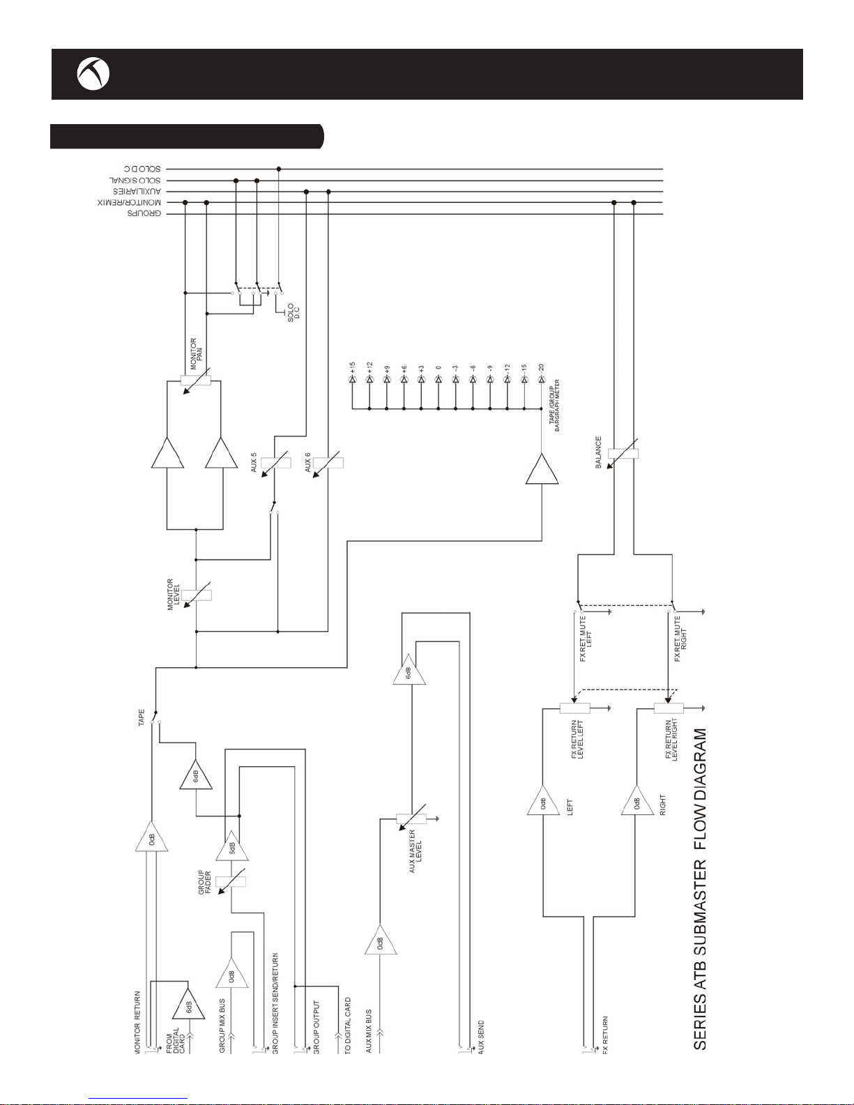
Reference to the Submaster module signal flow diagram will help to give a better understanding of the
way in which the signal is routed.
10
www.toftaudio.com
SUBMASTER FLOW DIAGRAM
11
Toft Audio Designs Series ATB Console
MASTER SECTION
MASTER SECTION General Description
The Master section of the ATB console contains all of the con-
trols that affect the overall functionality of the console.
An accurately matched 100mm stereo fader controls the level of
the master stereo balanced outputs.
A comprehensive talkback system is provided which incorpo-
rates a high quality electret microphone and amplifier with a
continuously variable level control. The signal can be routed to
either the 8 subgroups and master left/right outputs for ‘slate’
announcements (so that the title of a song can be recorded at
the beginning), or to the auxiliary sends so that the engineer can
communicate with the musicians when they are in a separate
room. When the ‘TALK TO GROUPS’ button is used, the monitor
signal is dimmed by 25db to avoid feedback in the control moni-
tor speakers.
Above the talkback section is the master monitor level control for
the control room speakers. This is a very important control as
without this turned up, it will not be possible to hear any signal
on the control room monitor speakers. Coupled with this control
is a ‘MONO’ pushbutton which combines the left/right moni-
tor signals so that it is possible to check mono compatability. It
should be noted that the mono facility is purely a monitor func-
tion and does not affect the main stereo left/right output which
remains as a true stereo image. A very useful further facility in
this section is the provision of an ‘ALT MONITOR’ pushbutton
which routes the monitor signal to a second set of output jacks
on the rear of the master section so that an alternative monitor
system can be set up. This makes it possible to listen to the sig-
nal on (for example), a different set of monitor speakers so that
comparisons can be made.
A pair of very accurate 12 segment bargraph meters indicate the
signal being sent from the master left/right stereo outputs. As an
extremely useful additional feature to these electronic meters, a
pair of conventional moving coil VU meters are provided which
read in parallel with the bargraph meters. This makes it possible
to compare the signal measured on the two different types of
meters. By their nature, bargraph meters such as the ones fit-
ted to to the Series ATB console, respond very quickly to signal
peak and therefore are useful when used on instruments with
12

www.toftaudio.com
complex dynamic waveforms such as pianos etc. This type of meter will therefore greatly assist
the engineer when it comes to avoiding distortion during recording. However, when used on less
complex waveforms generated by for example, an electric guitar, it is possible to under record the
instrument using a bargraph display as they will sometimes react too much to the peak amplitudes
of the signal and not the average amplitude. They will however, generally result in a better use
of the available dynamic range of the recording medium. An analogue meter such as the conven-
tional V.U. meter also fitted to the Series ATB console, responds mostly to the average level of the
programme, so can therefore be considered more useful when recording instruments such as an
electric guitar. The combination of electronic bargraph and analogue metering therefore provides
the user with the best of both worlds.
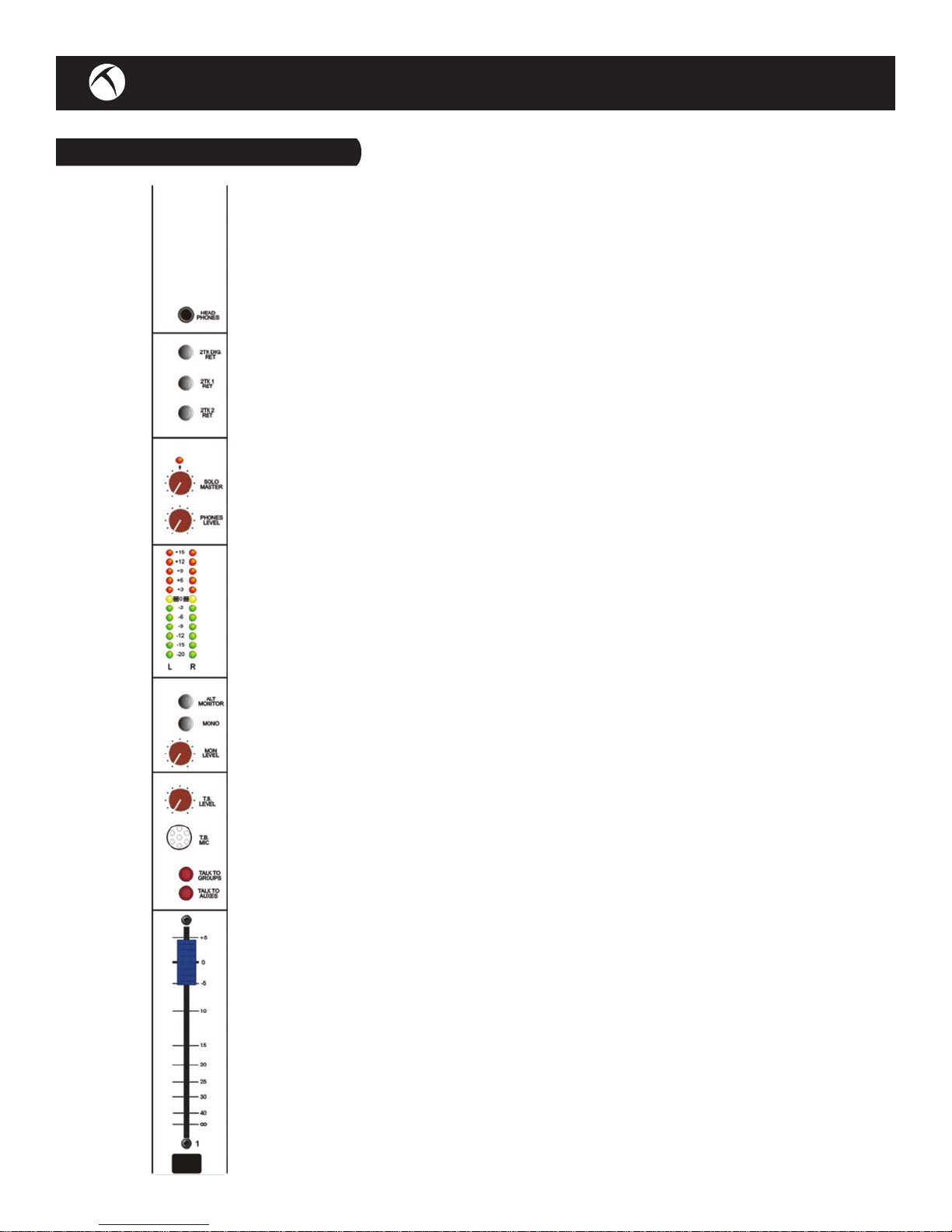
A headphone jack with a high quality stereo amplifier is provided so that if the engineer wishes to
monitor the console only on headphones, they can be connected to the jack socket at the top of
the master section. A separate stereo volume control is provided so that the level of the head-
phones can be adjusted independently.
A stereo master level control is also provided so that the volume of the AFL/PFL system can be
adjusted in the control room monitor speakers.
The final facility provided by the master section is the ability to monitor any one of three stereo
playback devices. ‘2TK 1 RET’ and ‘2TK 2 RET’ are conventional analogue connections located on
the rear of the submaster section so that the playback of a stereo device such as a cd player or
output of a computer sound card can be selected to the control room monitor speakers. ‘2TK DIG
RET’ is provided for use when the optional digital I/O card is connected. This routes the converted
analogue output of a digital playback device connected through the I/O card onto the control room
monitor speakers. The bargraph displays will meter the playback level and, when any of the three
buttons are depressed, it is no longer possible to listen to the master stereo output from the con-
sole. This is to make sure that when listening to an important final mix, nothing else will be moni-
tored. The signal will however still appear at the balanced master output jacks at the rear of the
master section and will also be controlled by the stereo master fader.
By selecting the appropriate pushbutton, it is therefore possible to listen to a stereo mix after it
has been recorded, providing an easy A/B comparison method.
Reference to the Master Section signal flow diagram will help to give a better understanding of the
way in which the signal is routed.
13

Toft Audio Designs Series ATB Console
MASTER FLOW DIAGRAM
14

www.toftaudio.com 15
OVERALL FLOW DIAGRAM

Toft Audio Designs Series ATB Console
OPERATIONAL DESCRIPTION
Multi-Track Recording Set Up
Make sure that all buttons are up and that all controls are in their default positions, i.e centre detented
potentiometers such as pan and equaliser boost/cut are in their centre positions, level controls and
equaliser frequency sweeps are at minimum (anti-clockwise). The channel fader should be set to
minimum.
The output from a balanced microphone should be wired in accordance with the information given in
section 2 of this manual and connected to the x-l-r input at the rear of the appropriate channel. If the
microphone requires +48 phantom power, this should be selected by depressing the ‘+48’ red button
at the top of the module.
The channel fader should be advanced to the top of its’ travel (maximum) and the mic/line level control
(at the top of the module) should be advanced until the green ‘-20’ l.e.d illuminates to a steady state.
This will indicate that there is signal present at the module output.
There are two ways to set up the console to record in a multi-track setup. If the console is only being
used in conjunction with an 8 track recorder or DAW, the signal can be sent via the ‘Submaster Out-
puts’ to the inputs of the recorder. The output of the 8 track recorder or DAW should be connected to
the ‘Monitor Returns’. If for example, you wish to route to track 5 of the multi-track recorder depress
the appropriate channel button marked ‘5-6’ and turn the channel pan control fully anti-clockwise (left).
The signal will now appear at the input of the 8 track recorder or DAW and the subgroup bargraph
display will indicate the level being sent to the recorder. To monitor the signal being replayed from the
DAW, depress the red ‘TAPE’ button on the appropriate submaster channel, turn up the ‘MON LEVEL’
control on the appropriate submaster channel and the signal will appear on the monitor speakers. The
‘MONITOR MASTER’ control in the Master section must be turned up. Since a lot of DAW’s (and of
course tape based recording systems) have automatic input/output monitoring systems such that when
a track is set to record the input is monitored through the playback outputs and then automatically
switches to playback when the track is not in record, the ‘TAPE’ button can be left depressed and the
DAW will provide the necessary monitor switching.
The second way of setting the console up is by using the ‘in-line’ monitoring facility provided on every
input. This system is to be favoured when using the console with anything more than an 8 track re-
cording system.
As each input module is provided with a direct output signal derived directly after the channel fader, this
can be used to feed the individual tracks of a multi-track recording device. Therefore the ‘DIR O/P’ jack
located on the rear panel behind each input should be connected to the appropriate input of the record-
ing device. It should be noted that connecting to the ‘DIR O/P’ jack does not break the signal path of
the input module, so all other facilities such as routing and panning to the 8 submaster groups is still
possible. This is especially useful since using the direct outputs only allows one signal to be routed to
each track. It is therefore necessary to use one of the sub groups only if a mix of a number of channels
is required. As the ‘DIR O/P’ jack does not break the signal path from the channel, it is a simple job to
connect from this jack directly to the input of the multi-track recorder or DAW.
16

www.toftaudio.com
To monitor the signal being recorded (via the multi-track recorders input/output monitoring system, the
recorder’s output should be connected to the balanced ‘MON’ jack located behind each input module.
This then connects the signal to the separate monitor section incorporated within each input module.
By turning up the appropriate ‘MON LEVEL’ control on an input module and adjusting the associated
‘MON PAN’ control, the signal can be listened to and placed anywhere between the left and right con-
trol room monitors. This of course is independent of any main channel panning that is taking place. By
this means a monitor mix of all 16, 24 or 32 channels can be built up depending on the mixer configu-
ration. The multi-track recorder’s own meters can be used to control the record level and monitor the
playback of the signal.
A further very useful feature is the ability to select auxiliary sends 5 and 6 to the monitor circuit by
means of the ‘AUX 5-6 TO MON’ pushbutton located next to the monitor level control. This makes
it possible to supply a headphone mix to artists during recording (by using for example auxiliary 5 as a
headphone feed) and also monitor reverb (or some other processing device) by using (for example) aux-
iliary 6. In this mode, pressing the ‘PRE’ pushbutton selects the auxiliary send signal either pre or post
the monitor level control. It is therefore extremely quick and easy to record and overdub using this sec-
tion of the console. An ‘EQ TO MON’ pushbutton completes the versatility of this section by making it
possible to route the entire four band equaliser onto the monitor section. This makes it possible to add
equalisation only on monitor to the track being recorded or playing back, so that it is possible to hear
how the mixed track might sound without actually recording it. In this mode, the eq. is now bypassed
on the channel section.
By using a combination of the channel direct outputs and the subgroups coupled with the channel and
subgroup monitor returns, it is of course possible to record a larger number of tracks than the console
has inputs. Therefore the 16 input console can be connected to a 24 track recorder, the 24 input con-
sole can be connected to a 32 track recorder and the 32 input console can be connected to a 40 track
recorder.
When it is required to use the console to mix down the recorded tracks, it is not necessary to re-plug
the console. By depressing the ‘I/P REV’ pushbutton at the top of the input module, the signal con-
nected to the ‘MON’ jack is routed to the channel line input. The signal therefore appears at the main
channel fader and can be routed to the stereo mix via the ‘L-R’ pushbutton and panned via the chan-
nel pan control. The normal channel facilities such as AFL, equalisation and auxiliary sends can now be
used. Whatever was plugged into the channel line input now appears at the monitor section and can
also be routed to the stereo mix via the monitor level control and pan. In this way, the number of input
channels to the stereo mix is doubled which greatly enhances the versatility of the console.
Recording With A Microphone
After routing the signal to the desired output, the channel fader should be put to the top of it’s travel
(maximum position) and the ‘INPUT GAIN’ control should be adjusted so that either the input meter
of the device that the microphone is being sent to reads an acceptable level or the channel input
level l.e.d’s (situated next to the channel fader), show the signal level. Using these meters, the level
should be adjusted until the red l.e.d just illuminates on peaks and the level control should then be
brought down so that the red l.e.d is just extinguished.
17
Other manuals for ATB series Console
1
Table of contents


