Fostex 1240 User manual

Owner’s
Manual
Model
\dP0/Wa&¥>0
RECORDING
MIXER
rostex
SAFETY
INSTRUCTIONS
1.
Read
Instructions
—
All
the
safety
and
operating
instruc¬
tions
should
be
read
before
the
appliance
is
operated.
2.
Retain
Instructions
—
The
safety
and
operating
instructions
should
be
retained
for
future
reference.
3.
Heed
Warnings
—
All
warnings
on
the
appliance
and
in
the
operating
instructions
should
be
adhered
to.
4.
Follow
Instructions
—
All
operating
and
use
instructions
should
be
followed.
5.
Water
and
Moisture
-
The
appliance
should
not
be
used
near
water
-
for
example,
near
a
bathtub,
washbowl,
kit¬
chen
sink,
laundry
tub,
in
a
wet
basement,
or
near
a
swim¬
ming
pool,
and
the
like.
6.
Carts
and
Stands
-
The
appliance
should
be
used
only
with
a
cart
or
stand
that
is
recommended
by
the
manur
facturer.
7.
Ventilation
—
The
appliance
should
be
situated
so
that
its
location
or
position
does
not
interfere
with
its
proper
venti¬
lation.
For
example,
the
appliance
should
not
be
situated
on
a
bed,
sofa,
rug,
or
similar
surface
that
may
block
the
ventilation
openings;
or,
placed
in
a
built-in
installation,
such
as
a
bookcase
or
cabinet
that
may
impede
the
flow
of
air
through
the
ventilation
openings.
8.
Heat
-
The
appliance
should
be
situated
away
from
heat
sources
such
as
radiators,
heat
registers,
stoves,
or
other
appliances
(including
amplifiers)
that
produce
heat.
9.
Power
Sources
-
The
appliance
should
be
connected
to
a
power
supply
only
of
the
type
described
in
the
operating
instructions
or
as
marked
on
the
appliance.
10.
G
r
ounding
or
Polarization
—
The
precautions
that
should
be
taken
so
that
the
grounding
or
polarization
means
of
an
appliance
is
not
defeated.
11.
Power
Cord
Protection
—
Power
supply
cords
should
be
routed
so
that
they
are
not
likely
to
be
walked
on
or
pinched
by
items
placed
upon
or
against
them,
paying
particular
attention
to
cords
at
plugs,
convenience
recep¬
tacles,
and
the
point
where
they
exit
from
the
appliance.
12.
Cleaning
-
The
appliance
should
be
cleaned
only
as
recommended
by
the
manufacturer.
13.
Nonuse
Periods—The
power
cord
of
the
appliance
should
be
unplugged
from
the
outlet
when
left
unused
for
a
long
period
of
time.
14.
Object
and
Liquid
Entry
—
Care
should
be
taken
so
that
objects
do
not
fall
and
liquids
are
not
spilled
into
the
enc¬
losure
through
openings.
15.
Damage
Requiring
Service
—
The
appliance
should
be
serviced
by
qualified
service
personnel
when:
A.
The
power
supply
cord
or
the
plug
has
been
damaged;
or
B.
Objects
have
fallen,
or
liquid
has
been
spilled
into
the
appliance;
or
C.
The
appliance
has
been
exposed
to
rain;
or
D.
The
appliance
does
not
appear
to
operate
normally
or
exhibits
a
marked
change
in.
performance;
or
E.
The
appliance
has
been
dropped,
or
the
enclosure
damaged.
16.
Servicing
-
The
user
should
not
attempt
to
service
the
appliance
beyond
that
described
in
the
operating
instruc¬
tions.
All
other
servicing
should
be
referred
to
qualified
service
personnel.
CAUTION
RISK
OF
ELECTRIC
SHOCK
DO
NOT
OPEN
CAUTION:
TO
REDUCE
THE
RISK
OF
ELECTRIC
SHOCK,
DO
NOT
REMOVE
COVER
(OR
BACK).
NO
USER-SERVICEABLE
PARTS
INSIDE.
REFER
SERVICING
TO
QUALIFIED
SERVICE
PERSONNEL.
The
lightning
flash
with
arrowhead
symbol,
within
an
equilateral
triangle,
is
intended
to
alert
the
user
to
the
presence
of
uninsulated
“dangerous
voltage”
within
the
product’s
en¬
closure
that
may
be
of
sufficient
magnitude
to
constitute
a
risk
of
electric
shock
to
persons.
The
exclamation
point
within
an
equilateral
triangle
is
intended
to
alert
the
user
to
the
presence
of
important
operating
and
mainte¬
nance
(servicing)
instructions
in
the
literature
accompanying
the
appliance.
“WARNING"
"TO
REDUCE
THE
RISK
OF
FIRE
OR
ELECTRIC
SHOCK,
DO
NOT
EXPOSE
THIS
APPLIANCE
TO
RAIN
OR
MOIS¬
TURE.”

TABLE
OF
CONTENTS
PAGE
SECTION
1
Introduction
2
SECTION
2
Name
and
Function/Operation
of
4
Controls
and
Switches
SECTION
3
Connections
with
External
Equipment
7
SECTION
4
Parametric
Equalizer
8
SECTION
5
Interconnections
with
Various
9
Processors
SECTION
1
.
INTRODUCTION
Thank
you
for
purchasing
a
Fostex
40-Series
Mixer.
Model
1240
has
12
inputs,
Model
1840,
18
inputs,
and
Model
2440,
24
inputs.
All
other
features
are
common
to
the
series.
These
consoles
are
particularly
well-suited
for
multitrack
recording
and
production/assembly
applications,
but
they
are
also
useful
for
PA
and
sound
reinforcement.
Features
include
phantom
powering,
complete
stereo
solo
monitoring,
four
channels
of
AUX
SEND
for
effects
processing
and
switchable
line
inputs
for
tape
returns/
musical
instruments.
Both
signals
can
be
monitored
simultaneously
without
sacrificing
double
input
channels.
A
unique
feature
of
these
mixers
is
the
fader
(patent
applied
for).
Made
of
a
conductive
rubber
roller
assembly,
the
action
is
much
smoother
and
more
accurate
than
the
conventional
brush
type
fader,
plus
this
new
design
will
last
longer
and
perform
more
quietly
—
47^V
p-p.
In
order
to
use
this
sophisticated
electronic
device
to
its
maximum
potential,
please
read
this
owner’s
reference
manual
thoroughly.
With
proper
use
and
maintenance,
you
will
enjoy
many
years
of
satisfied
performance.
PAGE
SECTION
6
Multitrack
Recording
10
SECTION
7
Other
Methods
of
Operation
17
SECTION
8
Trouble
Shooting
18
SECTION
9
Notes
on
After
Service
18
SECTION
10
Specifications
19
SECTION11
Block
Diagram
20
SAFETY
PRECAUTIONS
When
switching
on
power
to
this
unit,
always
be
sure
it
is
switched
on
before
switching
on
power
to
the
peripheral
equipment
to
which
the
output
is
connected
to
prevent
damage
to
the
speaker
by
a
large
noise
from
the
monitor
amplifier
or
to
avoid
shock
to
other
equipment
(recorder,
etc.).
Also,
when
plugging
or
unplugging
cables
to
the
input
and
output
jacks,
be
sure
the
faders,
gain,
or
trim
levels
are
set
to
minimum
(-
oo,
0
etc.).
Connection
to
the
power
supply
unit
*
When
POWER
is
switched
on,
the
POWER
LED
is
lit
and
power
is
applied
to
the
main
Unit.
(Be
sure
the
cable
from
the
power
supply
unit
is
plugged
into
the
main
unit,
before
switching
on
POWER.)
2

SECTION
2.
NAME
AND
FUNCTION/OPERATION
OF
CONTROLS
AND
SWITCHES
Letters
in
(
)
are
identical
to
panel
letterings.
In
the
explanations,
the
panel
lettering
will
always
precede
the
control
number.
(Ex:
PAN
(13);
EQ
(7);
etc.)
1.
INPUT
TRIM
(TRIM)
The
knob
for
trimming
the
preamplifier
gain
to
the
optimum
level
with
regards
to
the
input
signal
at
the
INPUT
jacks
(33)
and
(34).
It
can
comply
to
a
wide
range
from
mic
level
(-60dBV)
through
line
level
(-
lOdBV).
Please
note,
however,
that
this
control
has
no
affect
on
the
input
level
to
the
TAPE
IN
jack
(36).
2.
ALTERNATE
SELECT
SWITCH
(GROUP/SUB)
The
input
selector
switch
for
selecting
the
signal
to
each
channel
INPUT
faders
(17)
and
to
the
SUB
MIX
sections
(3)
and
(4).
GROUP:
Signals
from
INPUT
jacks
(33)
and
(34)
will
be
routed
to
the
INPUT
fader
(17),
and
the
signal
from
TAPE
IN
jack
(36)
to
SUB
MIX
sections
(3)
and
(4).
SUB
:
The
signal
from
TAPE
IN
jack
(36)
will
be
routed
to
the
INPUT
fader
(17),
and
signals
from
INPUT
jacks
(33)
and
(34)
to
the
SUB
MIX
sections
(3)
and
(4).
3.
SUBMIX
GAIN
KNOB
(SUB
GAIN)
Trims
the
sound
volume
of
the
signal
selected
by
(2).
4.
SUBMIX
PAN
POT
(SUB
PAN)
Sets
the
right
and
left
perspective
when
sending
the
signal
selected
by
(2)
to
the
buss
selected
by
the
CUE/L-R
selector
(5).
5.
CUE/STEREO
SELECTOR
SWITCH
(CUE/L-R)
Selects
whether
the
signal,
adjusted
in
sound
volume
and
perspective
in
the
SUB
MIX
sections
(3)
and
(4),
is
to
be
sent
to
CUE
buss
(CUE)
or
the
STEREO
buss
(L-R).
When
it
is
sent
to
the
CUE
buss,
it
will
be
output
to
the
CUE
OUT
jack
(46)
via
the
CUE
master
level
knob
(31),
and
when
sent
to
the
STEREO
buss,
it
will
be
output
to
STEREO
OUT
jacks
1
~2
(43)
via
the
STEREO
master
fader
(22).
Either
signal
can
be
monitored
with
the
MONITOR
selector
(26).
6.
PEAK
LED
(PEAK)
These
will
be
lit
when
signals
to
INPUT
jacks
(33)
and
(34)
or
TAPE
IN
jacks
(36)
are
in
an
overload
condition
(+
25dB)
(Not
only
in
the
preamplifier
but
it
will
also
light
when
the
EQ
(7)
section
overloads).
If
this
LED
is
lit
too
often,
it
must
be
set
to
the
optimum
level
by
TRIM
(1)
or
TAPE
trimmer
(*
Refer
to
NOTE
1).
For
details,
refer
to
“2.
Level
Matching
With
Ex¬
ternal
Equipment,”
page
7.
7.
PARAMETRIC
EQUALIZER
Adjusts
tone
of
the
signals
fed
to
each
channel
INPUT
faders
(17).
R»r
details,
refer
to
“Parametric
equalizer'’,
page
8.
8.
AUX
SEND
LEVEL
KNOB
(AUX
1
~
4)
The
knob
for
adjusting
the
level
of
the
four
AUX
send
channels.
AUX
1,
AUX
2:
In
relation
to
the
PRE/POST
selector
(9),
the
prefader
or
post¬
fader
(both
are
post
equalizers)
signals
will
be
sent
to
AUX
buss
1
and
2.
AUX
3,
AUX
4:
The
post
fader
(post
equalizer)
signal
is
sent
to
AUX
busses
3
and
4.
These
signals
sent
to
AUX
buss
1
~
4
are
output
to
AUX
OUT
jacks
1
~
4
(39)
via
AUX
master
GAIN
1
~
4
(23)
and
can
be
used
for
sends
such
as
to
at
effect
unit.
9.
AUX
1,
2
INPUT
SELECTOR
(PRE/POST)
Selects
the
signal
of
each
channel
to
be
connected
to
AUX
1
and
AUX
2
send
(8).
PRE
:
The
signal
from
EQ
(7)
and
immediately
before
the
INPUT
fader
(17)
is
connected.
POST:
The
signal
passing
through
EQ
(7)
and
INPUT
fader
(17)
is
connected.
10.
GROUP
1-2
ASSIGN
SWITCH
(1-2)
This
is
switched
ON
(button
is
pressed)
to
send
the
signal
input
to
the
INPUT
fader
(17)
to
the
GROUP
1,
2
buss.
The
signal
can
be
assigned
to
1
and
2
in
any
condition
of
balance
by
the
PAN
(13)
control.
The
signal
will
not
be
sent
to
buss
1
and
2
when
this
switch
is
OFF.
11.
GROUP
3-4
ASSIGN
SWITCH
(3-4)
Same
as
for
above
(10),
this
is
switched
ON
(button
is
pressed)
to
send
the
input
signal
to
GROUP
buss
3
and
4.
12.
STEREO
L-R
ASSIGN
SWITCH
(L-R)
Same
as
for
above
(10),
this
is
switched
ON
(button
is
pressed)
to
send
the
input
signal
to
the
STEREO
buss
L,
R.
The
signal
can
be
assigned
to
L
and
R
in
any
condition
of
balance
by
the
PAN
(13)
control.
The
relation
between
the
three
assign
switches
(10)
~
(12)
and
the
PAN
(13)
control
is
shown
below
(•
-
ON,
O
-
OFF).
Example:Sending
to
GROUP
Sending
to
GROUP
buss
4.
bussl.
•
p
<*!
M
Sending
to
GROUP
buss
1,
2
at
same
level.
©
Vf
O
Sending
to
GROUP
buss
1
~
4
and
STEREO
buss
L,
Sending
to
STEREO
buss
R.
R
at
same
level.
13.
GROUP
AND
STEREO
BUSS
PAN
POT
(PAN)
In
relation
with
the
(10)
~
(12)
assign
switches,
this
control
functions
as
shown
in
above
schematics.
14.
MUTE
BUTTON
(MUTE)
When
this
button
is
pressed,
the
LED
above
it
will
be
lit
and
the
signal
applied
to
the
INPUT
fader
(17)
for
that
channel
will
be
muted.
As
this
function
is
the
same
as
if
the
INPUT
fader
is
quickly
moved
down
to
infinitive,
it
is
convenient
when
it
is
desired
to
momentarily
cut
off
the
sound
without
moving
the
fader
position.
As
this
mute
is
effective
only
on
the
signal
immediately
after
the
INPUT
fader
(17),
it
will
not
affect
the
PRE
signal
connected
to
the
AUX
1,
2
send
(8)
or
the
sound
monitored
by
pressing
the
PFL
button
(15).
15.
PRE-FADER
LISTEN
BUTTON
(PFL)
When
this
button
is
pressed,
the
LED
above
it
will
be
lit
and
the
prefader
signal
(post
equalizer)
of
this
channel
is
sent
to
the
PFL
buss
(in
stereo
format)
in
center
perspective.
In
this
operation,
MONITOR
selector
(26)
is
by
passed,
and
the
PFL
buss
output
signal
(the
signal
after
passing
through
the
PFL/SOLO
level
knob
(30))
is
sent
to
the
MONITOR
level
knob
(28)
and
the
PHONES
level
knob
(29),
and
therefore,
you
can
monitor
in
center
perspective
the
pre-fader
signal
only
of
the
channel
whose
button
is
pressed.
Please
note,
however,
that
as
the
signals
in
solo
by
the
SOLO
buttons
(16),
(19),
(24)
and
(25)
will
also
be
sent
to
the
PFL
buss,
these
can
also
be
monitored
at
the
same
time.
Also,
when
at
least
one
of
these
buttons
is
pressed,
the
L,
R
section
of
the
meter
(32)
will
indicate
the
level
of
the
mixed
signal
(signal
immediately
before
the
PFL/SOLO
level
knob
(30))
on
the
PFL
buss
and
therefore,
may
be
used
to
confirm
the
pre-fader
level.
This
function
is
effective
only
on
the
monitor
system
(MONITOR
OUT
jack
1
-
2
(45),
PHONES
jack
(47),
METER
(32))
and
has
no
affect
on
other
outputs.
16.
INPUT
SOLO
BUTTON
(SOLO)
When
this
button
is
pressed,
the
LED
above
it
will
be
lit
and
the
post
fader
signal
of
this
channel
whose
button
is
pressed
is
sent
to
the
PFL
buss.
For
the
same
reason
as
above
(15),
it
will
be
possible
to
monitor
the
post
fader
signal
only
of
the
channel
whose
button
is
pressed
but
as
the
monitored
sound
can
be
confirmed
in
stereo
in
the
perspective
set
by
PAN
(13),
you
can
adjust
EQ
(7)
without
disturbing
the
initially
planned
perspective.
Please
note,
however,
that
other
signals
sent
to
the
PFL
buss
by
other
SOLO
buttons
and
PFL
buttons
(15),
will
also
be
heard.
Also,
when
at
least
one
of
these
buttons
is
pressed,
the
L,
R
section
of
the
meter
(32)
will
indicate
the
level
of
the
mixed
signal
on
the
PFL
buss
and
therefore,
the
post
fader
level
of
each
channel
can
be
easily
confirmed.
This
function
is
effective
only
on
the
monitor
system
(MONITOR
OUT
jacks
1
-
2
(45),
PHONES
jack
(47),
METER
(32))
and
has
no
affect
on
other
outputs.
17.
INPUT
FADER
Adjusts
the
sound
volume
of
the
signal
selected
by
GROUP/SUB
selector
(2).
As
noise
and
distortion
is
minimum
at
the
scale
range
of
0±5
(db),
it
is
recommended
to
initially
set
the
fader
within
this
range,
then
adjust
the
input
level
with
TRIM
(1).
18.
GROUP
MASTER
FADER
(1,
2,
3,
4)
These
are
the
individual
master
faders
for
the
GROUP
buss
1-4.
Not
only
the
output
levels
of
GROUP
OUT
jacks
1-4
(40)
but
also
the
send
level
to
the
GROUP
TO
STEREO
sections
(20)
and
(21)
are
adjusted
here.
These
are
normally
used
to
set
the
send
signal
levels
to
a
multitrack
recorder.
19.
GROUP
SOLO
BUTTON
(SOLO)
When
this
button
is
pressed,
the
LED
above
it
is
lit
and,
for
the
same
reason
as
above
(16),
the
output
signal
only
of
the
GROUP
buss
selected
can
be
monitored
in
the
center
perspective.
It
must
be
noted
that
signals
sent
to
the
PFL
buss
by
the
SOLO
button
and
PFL
button
(15)
will
also
be
heard
in
the
monitor.
In
addition,
if
one
or
more
SOLO
button
is
pressed,
the
meter
(32)
L
and
R
section
will
indicate
the
mixed
signal
on
the
PFL
buss.
This
function
is
effective
only
on
the
monitor
system
as
in
above
(16).
20.
GROUP
TO
STEREO
GAIN
KNOB
(GAIN
1
-
4)
The
knob
for
adjusting
individual
levels
of
the
GROUP
buss
1
-
4
output
signals
(the
signal
after
passing
GROUP
master
faders
1-4)
sent
to
the
STEREO
buss.
This
is
convenient
at
mixdown
when
you
wish
to
group
the
signals
by
the
GROUP
master
faders
1
-
4
(18)
before
sending
them
to
the
STEREO
buss.
21.
GROUP
TO
STEREO
PAN
POT
(PAN)
This
sets
the
left/right
perspective
when
sending
the
signal
from
(20)
to
the
STEREO
buss.
The
signal
from
(20)
and
this
pan
pot
is
the
output
from
STEREO
OUT
jacks
1-2
(43)
via
the
STEREO
master
fader
(22).
22.
STEREO
MASTER
FADER
(STEREO
MASTER)
The
master
fader
for
the
STEREO
buss.
Typically
the
master
recorder
is
connected
to
STEREO
OUT
jacks
1
and
2
(43)
and
the
send
level
can
be
adjusted
here.
23.
AUX
MASTER
GAIN
KNOB
(GAIN)
Adjusts
the
master
level
of
the
AUX
buss
1-4.
Levels
of
the
signal
output
from
AUX
OUT
jacks
1
-
4
can
be
set
by
these
knobs.
24.
AUX
SOLO
BUTTON
(SOLO)
When
this
button
is
pressed,
the
LED
above
it
is
lit,
and
just
as
for
the
GROUP
SOLO
buttons
1
-4(19),
the
AUX
buss
output
signal
only
of
the
button
pressed
can
be
monitored
at
the
center
perspective.
It
must
be
noted,
however,
that
the
signals
sent
to
the
PFL
buss
by
the
SOLO
buttons
and
PFL
buttons
(15)
will
also
be
heard
in
the
monitor.
Also,
if
even
one
of
these
buttons
is
pressed,
the
meter
(32)
L,
R
sections
will
indicate
the
mixed
signal
of
the
PFL
buss
and
therefore
may
be
used
to
confirm
the
output
levels
at
the
AUX
OUT
jacks
1-4
(39).
This
function
is
effective
only
on
the
monitor
system
in
the
same
way
as
in
(19).
5
25.2
TRACK
IN
SOLO
BUTTON
(2
TRK
IN
SOLO
1,
2)
This
is
pressed
to
monitor
the
master
recorder
output
connected
to
the
2
TRK
IN
jacks
1
and
2
(42).
When
this
button
is
pressed,
the
LED
above
it
will
be
lit
and,
as
for
other
SOLO
buttons,
the
input
signal
from
the
2
TRK
IN
jack
(42)
corresponding
to
the
button
number
(1
or
2)
that
is
pressed,
can
be
monitored
via
the
PFL
buss.
Also,
if
one
of
either
button
is
pressed,
the
meter
L,
R
section
will
indicate
the
mixed
signal
of
the
PFL
buss
and
thus
may
be
used
to
confirm
the
output
level
of
the
master
recorder
that
is
connected.
This
function
is
effective
only
on
the
monitor
system
as
in
(24).
26.
MONITOR
SELECTOR
(MONITOR
SELECT)
Selects
the
signal
to
be
sent
to
the
MONITOR
OUT
jacks
1
-
2
(45)
and
PHONES
jack
(47).
STEREO:
Signals
(STEREO
buss
output
signals)
output
from
the
STEREO
OUT
jacks
1
and
2
(43)
can
be
monitored.
CUE
:
Signals
(CUE
buss
output
signals)
output
from
the
CUE
OUT
jacks
(46)
can
be
monitored.
Down
position
is
ON
and
up
position
is
OFF
for
these
buttons.
Also,
please
note
that
these
two
buttons
are
the
LOCK
RELEASE
type
(only
one
of
either
button
can
be
pressed).
27.
MONITOR
OUT
SELECTOR
(MONITOR
OUT)
This
is
for
selecting
whether
1
(RCA
pin
jack)
or
2
(stereo
phone
jack)
of
the
MONITOR
OUT
jack
(45)
is
to
be
active.
As
both
1
and
2
are
at
the
same
level
(-10dBV)
and
same
impedance
(10KQ
load),
the
selection
depends
on
the
connector.
MONITOR
OUT
Select
f
Q
1
*
=
^
>
O
O
l=£>
|*£j>
t0f
|
I
©
I
Large
monitor
speaker
either
one
\
M0
*
0
UT
1
,—
T
—,
l
»-»
2
l=£>
©
I-[>
|
M
a
t
^p°
r
|
<=>
[O]
Small
monitor
speaker
Example
28.
MONITOR
LEVEL
KNOB
(MONITOR)
Adjusts
the
output
level
of
the
signal
output
from
MONITOR
OUT
jacks
1
and
2
(45).
29.
HEADPHONE
LEVEL
KNOB
(PHONES)
Adjusts
sound
level
of
the
headphones
plugged
into
the
PHONES
jack
(47).
30.
PREFADER
LISTEN/SOLO
LEVEL
KNOB
(PFUSOLO)
Adjusts
the
master
level
of
the
PFL
buss.
The
total
sound
volume
can
be
set
at
solo
monitoring
by
pressing
the
PFL
button
(15)
or
SOLO
button.
31.
CUE
MASTER
LEVEL
KNOB
(CUE
MASTER)
The
CUE
buss
master
level
adjusting
knob.
Output
level
at
the
CUE
OUT
jack
(46)
can
be
set.
This
is
convenient
for
setting
the
total
sound
volume
when
sending
to
the
CUE
buss
the
signals
of
SUB
MIX
sections
3
and
4
by
the
CUE/L-R
selector
(5).
Please
note
that
when
at
least
one
PFL
button
(15)
or
SOLO
button
is
pressed,
the
L
and
R
meters
will
indicate
the
mixed
signal
level
on
the
PFL
buss.
33.
X
L
R
INPUT
JACKS
These
are
XLR
type
balanced
input
connectos
(#3
pin
hot)
which
match
signals
from
mic
levels
to
line
levels.
They
can
also
match
unbalanced
type
input
signals
but
then
pins
#1
and
#2
must
be
GND
and
the
PHANTOM
POWER
switch
(35)
must
be
switched
OFF
at
all
times.
If
a
plug
is
inserted
into
the
phone
INPUT
jack
(34),
that
jack
will
have
priority
and
the
signals
to
the
XLR
connector
will
be
by-passed.
34.
P
H
O
N
E
INPUT
JACKS
(INPUT)
These
are
unbalanced
phone
jacks
which
signals
from
mic
levels
to
line
levels.
They
can,
of
course,
match
the
balanced
line
type
input
signals
but
then
the
plug
tip
must
be
hot
and
the
ring
cold.
35.
PHANTOM
POWER
SWITCH
(
+
48V)
The
ON/OFF
switch
for
the
DC48V
phantom
power
to
the
microphone.
This
must
always
be
switched
OFF
(button
up
position)
when
a
dynamic
microphone
is
used
because
it
does
not
require
a
power
supply.
When
this
is
switched
ON,
pin
#
1
will
be
0
volt
and
DC48
volts
will
be
applied
to
pins
#2
and
#3.
36.
TAPE
INPUT
JACKS
(TAPE)
Normally,
the
outputs
(unbalanced)
of
a
multitrack
recorder
are
plugged
in
here.
These
are
set
for
the
rated
input
level
of
-
lOdBV
(20K0)
before
leaving
the
production
line
(Refer
to
NOTE
1
of
the
P.O.).
37.
ACCESSORY
SEND/RECEIVE
JACKS
(SEND/RCV)
These
jacks
are
used
for
plugging
in
external
sound
processors
such
as
digital
reverbs,
compressors/
limiters
and
noise
gates.
These
are
in
stereo
phone
format
(TIP
is
send,
RING
is
receive)
and
when
nothing
is
plugged
in
here,
the
signal
will
be
jumpered
from
send
to
receive.
GND
insert
[
|_
RING
TIP
GNO
(Connected
to
TIP
|
u
To
effector
(SEND)
—
From
effector
(RECEIVE)
T\_
GND
I
Connected
to
RING~1
38.
D
I
R
E
CT
OUT
JACK
(D.
OUT)
The
output
jacks
of
the
post
fader
(post
equalizer)
signals
of
each
channel.
These
can
be
used
for
sends
to
the
effect
unit.
32.12
POINT
LED
BARGRAPH
METERS
These
indicates
the
output
levels,
from
left
to
right,
at
the
GROUP
OUT
jacks
1,
2,
3,
4
(40)
and
the
STEREO
OUT
jack
1
(43)
L,
R.
39.
A
U
X
OUT
JACKS
(AUX
OUT
1,
2,
3,
4)
Output
jacks
of
the
AUX
buss
1
~
4.
Used
for
sending
the
mixed
signal
of
the
AUX
1
~
4
send
(8)
to
the
digital
reverb.
40.
GROUP
OUT
JACKS
(GROUP
OUT
1,
2,
3,
4)
Output
jacks
of
the
GROUP
buss
1
~
4
which
are
normally
used
for
sends
to
the
multitrack
recorder.
41.
GROUP
IN
JACKS
(GROUP
IN
1,
2,
3,
4)
Input
jacks
of
the
GROUP
buss
1
~
4.
Normally,
effects
returns
and
outputs
of
other
mixers
are
plugged
in
here
and
used
for
mixing
into
the
GROUP
buss.
42.
2
TRACK
IN
JACKS
(2
TRK
IN
1
~
2)
Master
recorder
outputs
are
normally
connected
here.
Playback
of
the
master
tape
can
be
simply
monitored
by
selecting
the
2
TRK
IN
SOLO
button
1
~
2
(25).
43.
STEREO
OUT
JACK
(STEREO
OUT
1
~
2)
Output
jacks
of
the
STEREO
buss.
These
are
normally
used
for
sends
to
the
master
recorder.
Although
signals
via
the
STEREO
master
fader
(22)
will
be
sent
both
to
1
(RCA
pin
jacks)
and
2
(stereo
phone
jacks),
their
rated
output
levels
will
be
-lOdBV
at
1
(RCA
pin
jacks)
and
+
2dBV
(+
4dBs)
at
2
(stereo
phone
jacks),
and
either
level
can
be
chosen
for
your
particular
application.
The
polarity
of
2
(stereo
phone)
is
L
for
the
TIP
and
R
for
the
RING.
44.
STEREO
IN
JACK
(STEREO
IN)
Input
jacks
of
the
STEREO
buss.
These
jacks
are
used
to
connect
the
stereo
outputs
of
another
mixer
or
effects
returns
for
mixing
into
the
STEREO
buss.
45.
MONITOR
OUT
JACKS
(MON
OUT
1
-
2)
The
signal
selected
by
the
MONITOR
selector
(26)
is
output
here
via
the
MONITOR
level
knob
(28).
If
at
least
one
PFL
button
(15)
or
SOLO
button
is
pressed,
the
PFL
buss
output
signal
(the
signal
passing
through
the
PFL/SOLO
level
knob
(30))
will
be
the
output
here
via
the
MONITOR
level
knob
(28).
SECTION
3.
CONNECTIONS
WITH
1.
IMPEDANCE
Input
and
output
impedances
should
always
be
considered
when
connecting
this
unit
to
other
equipment.
Impedance
is
the
resistance
value
against
alternating
currents
such
as
sound
signals
and
the
unit
of
measurement
is
Q
(Ohm).
If
the
output
impedance
of
a
given
unit
does
not
match
the
input
impedance
of
the
other,
sound
distortion
or
even
equipment
breakdown
could
occur.
In
general,
the
rule
is
that
output
impedance
should
be
low
(low
out)
and
input
impedance
should
be
high
(high
receive).
Refer
to
SPECIFICATIONS
in
page
19
for
input/output
impe¬
dance
of
this
unit.
NOTE:
Always
use
a
Direct
Box
when
interconnec¬
ting
outputs
indicated
in
watts,
(W)
such
as
that
of
a
power
amplifier,
with
a
high
impedance
input.
If
this
precaution
is
not
followed,
severe
damage
may
result.
In
this
function,
only
one
of
either
1
(RCA
pin
jack)
or
2
(stereo
phone
jack)
will
be
effective
(Refer
to
MONITOR
OUT
selector
(27)).
The
polarity
of
2
(stereo
phone)
is
L
for
the
TIP
and
R
for
the
RING.
46.
CUE
OUT
JACK
(CUE
OUT)
The
output
jacks
of
the
CUE
buss.
The
mixed
signal
of
the
SUB
MIX
sections
(3),
(4)
can
be
this
output
via
the
CUE
master
level
knob
(31).
This
mix
is
a
convenient
monitor/cue
for
the
musicians.
47.
HEADPHONE
JACK
(PHONES)
The
same
source
at
MONITOR
OUT
jacks
1
-
2
is
the
output
here.
48.
PREFADER
LISTENfSOLO
INDICATING
LED
(PFL/SOLO)
This
will
be
lit
when
at
least
one
of
the
PFL
button
(15),
SOLO
buttons
(16),
(19),
(24),
or
(25)
is
pressed.
While
this
LED
is
lit,
the
PFL
buss
output
signal
will
be
sent
to
the
MONITOR
OUT
jacks
1
~
2
(45)
and
the
PHONES
jack
(47),
and
the
mixed
signal
of
the
PFL
buss
will
be
indicated
on
the
L,
R
sections
of
the
meter
(32).
49.
POWER
LED
(POWER)
This
is
lit
when
power
is
applied
to
the
POWER
supply
connector
(50).
50.
POWER
SUPPLY
CONNECTOR
(POWER)
*
NOTE
1:
THE
TAPE
TRIMMER
This
trimmer
is
for
matching
the
input
level
of
this
units’
TAPE
IN
jack
(36)
with
a
recorder
whose
output
level
is
other
than
-lOdBV.
Although
its
variable
range
is
-16dBV
~
+
20dBV,
it
is
adjusted
to
-lOdBV
at
leaving
the
plant
and
Fostex
multitrack
recorders
such
as
Model
E-16,
E-8
and
80
can
be
connected
without
any
adjusting.
EXTERNAL
EQUIPMENT
2.
LEVEL
MATCHING
WITH
EXTERNAL
EQUIPMENT
Matching
the
level
of
the
external
equipment
connec¬
ted
to
the
INPUT
jacks
(33)
and
(34)
of
this
unit
is
done
by
the
TRIM
(1)
controls.
Adjust
so
that
the
PEAK
LED
(6)
does
not
frequently
flash
on
the
signal
peaks.
As
noise
and
distortion
is
the
least
in
the
range
of
0
±
5
(dB)
of
the
INPUT
faders
(17),
it
is
recommended
to
preset
them
within
this
range,
then
adjust
the
level
with
TRIM
(1).
During
this
operation,
if
the
PFL
button
(15)
and
INPUT
SOLO
button
(16)
are
pressed
in
advance,
the
prefader
and
post-fader
levels
and
tone
can
be
conveniently
checked.
However,
as
the
PEAK
LED
(6)
will
be
lit
during
overloading
at
EQ
(7),
each
gain
of
EQ
(7)
should
be
kept
flat
when
adjusting
TRIM
(1).
After
setting
TRIM
(1),
if
the
PEAK
LED
should
be
lit
during
testing
of
the
tone
by
EQ
(7),
there
is
overloading
at
the
EQ
stage
(7)
and
the
corresponding
gain
should
be
decreased,
or
re-adjust
TRIM
(1).
7

In
regards
to
level
matching
of
external
equipment
TAPE
IN
jack
(36)
of
this
unit,
refer
to
NOTE
1:
TAPE
Trimmer,
page7.
As
inputs
other
than
the
above
and
all
outputs
are
at
the
rated
level
of
-lOdBv
(0.3V)
except
for
STEREO
OUT
jack
2
(43),
the
outputs
will
thus
be
low
impedance
sends
and
therefore
can
be
connected
to
all
Fostex
recording
equipment
and
personal
studio
equipment.
On
the
other
hand,
it
may
be
necessary
to
use
an
attenuator
and
line
amplifier
(Fostex
Model
5030,
etc.)
when
connecting
to
equipment
with
different
+4dBm
rated
input/output
levels.
SECTION
4.
PARAMETRIC
EQUALIZER
A
fixed
frequency
10KHz
shelving
type
equalizer
and
a
2
band
parametric
equalizer
which
covers
different
frequencies
are
provided
at
each
input
channel
of
this
unit.
The
two
parametric
equalizers
can,
respectively,
be
set
at
any
frequency
within
the
ranges
of
60Hz
—
1
KHz
and
400Hz
-
6KHz.
It
is
possible
of
boost
or
cut
in
the
±
15dB
range,
and
will
be
highly
effective
in
adding
character
to
the
tone
by
allowing
control
of
the
fundamental
frequency
and
harmonic
overtones
which
determine
the
timbre
of
musical
instruments
and
the
human
voice.
NOTE:
Although
the
parametric
equalizer
is
highly
effective
in
correcting
mistake
in
the
original
sound,
during
microphone
recording,
it
is
important
to
try
changing
mic
positioning
or
using
another
type
of
mic
to
obtain
the
desired
timbre
before
relying
on
the
equalizer.
TYPICAL
EQUALIZATION
RESPONSE
GRAPH
•
Depth
of
sound
by
controlling
frequency
around
100Hz
•
Add
character
by
controlling
frequency
around
1kHz
•
Voluminous
sound
by
boosting
2
~
4kHz
•
Clarity
by
boosting
around
6kHz
•
Sound
brilliancy
by
boosting
above
8kHz
INSTRUMENT
CUTTING
BOOSTING
Human
Voice
Scratchy
at
2kHz
Nasal
at
1
kHz
Popping
p’s
below
80Hz
Hot
at
8
or
12kHz
Clarity
above
3kHz
Body
at
200
-
400Hz
Piano
Tinny
at
1
-
2kHz
Boomy
at
320Hz
Presence
at
5kHz
Bass
at
125Hz
Electric
Guitar
Muddy
below
80Hz
Clarity
at
3.2kHz
Bass
at
125Hz
Acoustic
Guitar
Tinny
at
2
-
3.2kHz
Boomy
at
200Hz
Sparkle
above
5kHz
Full
at
125Hz
Electric
Bass
Tinny
at
1
kHz
Boomy
at
125Hz
Growl
at
620Hz
Bass
below
80Hz
String
Bass
Hollow
at
620Hz
Boomy
at
200Hz
Slap
at
3.2
-
5kHz
Bass
below
200Hz
Snare
Drum
Annoying
at
1
kHz
Crisp
above
2kHz
Full
at
125Hz
Deep
at
80Hz
Bass
Drum
Floppy
at
620Hz
Boomy
below
80Hz
Slap
at
3.2
-
5kHz
Bass
at
80
—
125Hz
8

SECTION
5.
INTERCONNECTIONS
WITH
VARIOUS
PROCESSORS
Numerous
varieties
of
processes
such
as
digital
reverb
and
delay,
cnmpressor/iimiter
and
noise
gates
are
indis¬
pensable
tools
of
music
production
in
recent
years.
The
Series
40
units
are
provided
with
inputs
and
outputs
convenient
For
connecting
these
processor
such
as
AUX
OUT
jack
1
~
4
(39).
SEND/RCV
jack
(37),
D.GUTjack
(33),
GROUP
IN
jack
1
-
4
(41),
etc.
Among
these,
the
i
and
2
AUX
OUT
jack
(39)
can
be
selected
For
pre-fader
mix
or
post-fader
mix
and
either
can
he
chosen
according
to
the
application,
The
GROUP
IN
jacks
1
-
4
(41)
and
STEREO
IN
Jacks
(44)
are
Actual
connections
are
shown
in
the
following
examples:
Fin-1
USING
INDIVIDUAL
PROCESSORS
AT
EACH
INPUT
CHANNEL
Thre
connection
Is
eFFaclive
^jr
or-tx;-
normally
used
for
effects
returns
but
if
there
are
more
returns,
It
will
be
easier
to
feed
ail
of
these
to
another
mixer
before
returning
them.
Also,
even
though
all
INPUT
faders
(17)
are
in
use
at
the
multitrack
recorder
outputs,
the
input
signals
at
the
INPUT
jacks
(33)
and
(34)
can
be
stereo
mixed
in
the
SUB
MIX
sections
(3)
and
(4)
by
the
alternate
change
function,
and
therefore,
by
patching
the
effects
outputs
to
the
INPUT
jacks
(33)
and
(34),
the
same
number
of
returns
as
in
pul
channels
Gan
be
sent
to
the
master
recorder.
Sg.2
USING
A
PROCESSOR
COMMON
TO
ALL
INPUT
CHANNELS
TO
SEND
RETURNS
IN
INDIVIDUAL
AMOUNTS
AND
PERSPECTIVES
TO
EACH
CHANNEL
fl
Amount
Of
effect
appfer!
to
each
dhan-
neJ
is
separator
extolled
h&e
Pre-fader
signals
can
also
bo
S^nt
if
AUK
H
-
1
Tiwg
rt.ua;
sc
rtf
channels
are
used-
fix
LiLuTL-u
input
tvcci
processors.
OUT
R
Processor
[
3z
b
Ek)
Total
reverb*
ytc
San
as
=in
4
1
,
I
he
processor
output
cas-
be
returned
to
INPUT
jacks
C33J.
W\
and
TAPE
IN
jacks
(36k
(In
doing
so.
be
CaruM
not
to
crustu
a
lOOpI
9

SECTION
6.
MULTITRACK
RECORDING
Models
1240/1840/2440,
with
Fostex
Models
E-16,
E-8
and
80,
completely
support
all
processing
stages
of
multitrack
recording.
A
representative
example
of
multitrack
recording
by
a
combination
of
the
Model
1840
and
Fostex
E-16,
is
explained
in
the
following.
NOTE:
Models
1240/1840/2440
have
four
channels
of
group
outputs.
The
most
convenient
set-up
with
multitrack
recorders
is
via
a
patch
bay
like
the
3010
and
route
the
signals
by
patching
them
at
the
front
of
the
3010,
but
care
must
be
exercised
in
the
following
points.
E-16:
In
the
E-16,
INPUTS
9
~
16
are
normalled
jacks
wired
in
parallel
with
INPUTS
1
~
8.
In
other
words,
if
nothing
is
plugged
into
jacks
9-16,
the
same
signal
is
sent
to
channels
1
and
9,
2
and
10,
...
8
and
16.
If
this
feature
is
to
be
utilized,
you
need
only
connect
INPUTS
1
~
8
to
the
3010
patch
bay.
E-8
&
Model
80:
As
INPUTS
5
~
8
are
normalled
jacks
wired
in
parallel
with
INPUTS
1
~
4
in
this
recorder,
you
need
not
use
the
3010
the
same
way
as
with
E-16.
The
GROUP
OUT
buss
signal
of
this
unit
(Models
1240/1840/2440)
can
be
recorded
on
any
track
of
the
E-8
(Model
80)
if
the
GROUP
OUT
jacks
1
~
4
(40)
are
directly
connected
to
INPUTS
1
-
4
of
the
E-8.
However,
if
you
wish
to
record
on
more
than
five
tracks
in
one
pass,
either
use
the
STEREO
OUT
jack
1
(43)
in
parallel
with
the
recorder
send
(in
this
case,
six
tracks
can
be
recorded),
or
if
more
sends
are
required,
it
is
recommended
to
use
D.OUT
jacks
(38)
in
parallel.
It
is
possible
to
also
use
the
CUE
OUT
jack
(46)
but
in
this
case,
while
sending
input
signals
from
INPUT
jacks
(33)
and
(34)
to
SUB
MIX
sections
(3)
and
(4)
by
setting
the
GROUP/SUB
selector
(2)
to
SUB,
you
must
set
the
CUE/L-R
selecter
(5)
to
CUE
and
send
the
input
signal
to
the
CUE
OUT
jack
(46)
(In
this
case,
8
track
recording
is
possible
without
using
the
D.OUT
jack
(38)
but
tone
adjusting
by
EQ
(7)
is
not
possible).
In
either
case,
be
extremely
careful
to
prevent
forming
a
feedback
loop.
1
I
RECORDING
OF
THE
BASIC
TRACK
What
is
the
basic
track?
In
multitrack
recording,
the
first
step
is
usually
the
Rhythm
track
and
consists
of
an
combined
unit
of
important
parts
which
determine
the
outline
of
the
music.
This
"Rhythm
track”
is
also
called
the
“Basic
track”.
NOTES
BEFORE
OPERATING
In
the
operating
example
of-Fig.
1,
the
STEREO
buss
is
also
used
for
sending
signals
to
the
recorder.
If
recording
work
is
to
be
started
by
this
method,
you
should
always
first
set
all
CUE/L-R
selector
(5)
to
CUE
to
prevent
a
feed¬
back
loop.
For
the
same
reason,
set
all
GROUP/SUB
selectors
(2)
to
GROUP.
Please
refer
to
Fig.
4.
This
is
an
example
of
separately
recording
seven
tracks
in
one
pass.
It
is
the
method
of
picking
up
sounds
such
as
dram,
electric
base,
electric
guitars
by
a
multiple
number
of
microphones
and
recording
these
in
one
pass
on
tracks
1
~
7
of
E-16.
After
completing
level
matching
and
timbre
of
each
sound
source
(Refer
to
page
7,
“2.
Level
Matching
With
External
Equipment”
and
“THE
PARAMETRIC
EQUALIZER,”
page
8.)
note
the
settings
for
sending
these
signals
to
the
E-16.
E-16
TRACK
CHART
TRK
1
2
3
4
5
|
6
7
SOURCE
EB
(Elec.
base)
KICK
(Bass
drum)
SD
(Snare
drum)
HI-HAT
(hi-
hat)
L<—.—
R
TOM
RIDE
CRASH
EG
(Elec.
guitar)
Procedure
1
Following
is
the
procedure
for
assigning
each
sound
source
to
each
track.
TRK
1:
As
the
signal
from
GROUP
OUT
jack
1
(40)
is
routed
to
TRK
1,
EB
plugged
into
the
channel
17
INPUT
fader
(17)
(GROUP/SUB
selector
(2)
-
GROUP)
is
routed
to
GROUP
buss
1
(ASSIGN
1-2
switch
(10)
-
ON,
PAN
(13)
-
ODD).
Then,
for
setting
level
of
the
GROUP
buss
1
signal
going
to
the
GROUP
OUT
jack
1
(40),
the
GROUP
master
fader
1
(18)
is
adjusted
(can
be
checked
by
1
of
meter
(32)
1).
Be
sure,
however,
that
GROUP
TO
STEREO
GAIN
1
(20)
is
set
to
full
-
oo
to
prevent
this
signal
from
being
applied
to
the
STEREO
buss
and
recorded
on
tracks
5
and
6.
TRK
2:
In
the
same
way
as
for
TRK
1,
the
channel
1
KICK
is
sent
to
the
GROUP
buss
2
at
the
setting
in
the
schematic.
Setting
of
the
send
level
by
the
GROUP
master
fader
2
(40)
(checking
by
the
meter
2
(32))
and
fully
retarding
the
GROUP
TO
STEREO
GAIN
2
(20)
is
the
same
as
above.
TRK
3:
TRK
4:
Same
procedure
as
for
TRK
1
and
2.
TRK
5:
TRK
6:
As
GROUP
buss
1
~
4
are
all
in
use,
the
STEREO
buss
is
used
for
sends
to
TRK
5
and
TRK
6.
As
shown
in
the
schematic,
STEREO
OUT
jack
1
(43)
is
patched
to
INPUT
5
(
■
<-L)
and
6
(-R)
of
the
E-16.
TOM
(x2),
RIDE,
CRASH
are
mixed
in
stereo
perspective
and
recorded
on
TRK
5
and
6.
Each
sound
source
is
sent
to
the
STEREO
buss
by
setting
the
channel
4-7
assign
L-R
switch
(12)
to
ON
and
PAN
(13)
to
the
setting
shown
in
the
schematic,
and
send
level
to
the
recorder
adjusted
by
the
STEREO
master
fader
(22).
The
level
can
normally
be
confirmed
by
L
and
R
of
the
meter
(32)
but
please
note
that
it
will
indicate
the
PFL
buss
mixed
signal
level
when
the
PFL/SOLO
LED
(48)
is
lit.
TRK
7:
EG
send
to
TRK
7
is
done
by
patching
the
D.OUT
jack
(38)
to
the
E-16
INPUT
7.
Assign
switches
(10),
(11),
(12)
are
switched
OFF
to
prevent
the
EG
sound
to
be
recorded
on
other
tracks.
Also,
the
send
level
is
adjusted
by
the
channel
18
INPUT
fader
(17)
(Dotted
lines
in
the
schematic).
Procedure
2
In
general,
there
are
two
methods
of
monitoring.
Method
1:
Listen
to
the
sound
to
be
sent
to
the
recorder
(input).
Method
2:
Listen
to
the
sound
returned
from
the
recorder
(tape).
In
the
example
of
Fig.
1,
monitoring
is
by
Method
2
but
Method
1
will
be
explained
first
(It
is
recommended
to
normally
monitor
by
Method
2).
[Method
1]
The
solo
monitor
function
of
this
unit
is
a
straight
stereo
format
(Fixed
to
center
perspective
for
PFL
function
and
AUX
&
GROUP
solo
function):
the
signals
can
be
control
(There
could
be
differences
in
sound
volume
balance
of
each
sound
source
and
the
balance
of
that
actually
sent
to
the
recorder,
depending
on
the
GROUP
and
STEREO
master
fader
(18)
and
(22)
settings.),
if
the
INPUT
SOLO
buttons
(16)
of
channels
1
-
7,
17,
18
are
pressed
with
the
PFL/SOLO
level
knob
(30)
advanced.
On
the
other
hand,
if
the
GROUP
buss
1
-
4
only
is
used
for
sends
to
the
recorder,
it
can
be
monitored
at
the
same
sound
volume
balance
(only
at
center
perspective)
as
that
being
sent,
by
pressing
the
GROUP
SOLO
buttons
1
-
4
(19).
[Method
2]
To
monitor
the
recorder
output,
normally,
the
SUB
MIX
sections
(3)
and
(4)
are
used
as
shown
in
Fig.
1.
If
this
method
is
used,
the
sound
can
be
monitored
at
any
sound
volume
and
perspective
without
regards
to
the
recording
level
of
each
track,
thus
it’s
advantage
over
the
previous
Method
1.
In
the
E-16
(E-8,
Model
80),
signals
applied
to
the
inputs
are
also
heard
at
the
outputs
of
the
track
in
the
recording
mode
(=
INPUT
MONITOR).
In
addition,
regardless
of
whether
it
is
to
be
recorded
or
not,
the
specified
track
can
be
set
to
input
monitor
and
tracks
other
than
this
to
tape
monitor
(=
tape
sound
sync
playback)
by
the
INDIV.,
input
monitor
function.
In
either
case,
the
example
in
Fig.
1
shows
mixing
of
the
E-16
TRK
1
—
7
output
signals
in
the
SUB
MIX
sections
(3)
and
(4).
The
E-16
TRK
1-16
outputs
(OUTPUT
1-16)
connected
to
the
TAPE
IN
jacks
(36)
are
already
routed

to
SUB
GAIN
(3)
of
channels
1
~
16
selection
of
the
GROUP/SUB
selector
(2)
in
the
schematic,
but
as
the
ouput
of
TRK
1
~
7
are
to
be
monitored
here,
all
SUB
GAIN
(3)
other
than
channels
1
—
?
must
be
set
to
Set
MONITOR
selector
(26}
tc
CUE
to
allow
listening
to
the
CUE
buss
sound
(this
is
because
sounds
of
TOM,
etc,
are
already
on
the
STEREO
buss},
and
set
all
CUE/L-
R
selector
(5)
to
CUE
(to
prevent
cresting
s
loop}.
By
this
setup,
the
total
sound
can
be
adjusted
by
the
CUE
master
level
knob
(31},
and
each
sound
volume
and
perspective
for
TRK
1
-
7
can
be
adjusted
by
the
channel
1
~
7
SUB
MIX
sections
(3}
ana
(4),
In
this
exam
pi
e,
the
SUB
PAN
(4}
is
set
With
consideration
to
the
perspective
plan
at
mixdown
(Raise
the
MONi
IOR
level
knob
(2B)
when
using
the
monitor
speaker,
and
the
PHONES
level
knob
(29)
for
monitoring
with
the
headphones.}.
RECORDING
WITH
ADDED
EFFECTS
In
the
example
of
Fig.
1,
the
monitored
sound
was
"dry"
(raw
sound
with
no
effects
added},
but
it
is
often
desired
to
record
on
the
assumption
that
effects
will
be
added
(or
effects
sound
sent
to
the
monitor
system
only
wlthoui
recording
on
tape)
later
at
mixdown.
For
example,
if
SD
and
others
are
to
be
monitored
with
reverb
added,
it
could
he
doms
as
follows.
1.
The
sound
source
signals
are
sent
to
the
reverb
unit
using
the
AllX
1
~
4
sends
(3}
of
the
channel
(channel
2
if
it
:s
SD}
on
which
reverb
is
to
be
added,
(Refer
to
"INTERCONNECTION
WITH
VARIOUS
PROCESSORS",
page
9,}
2.
Return
the
reverb
output
to
the
INPUT
jacks
(33),
(34}
of
an
open
channel
(such
as
channels
15,
16)
and
send
it
to
the
SUB
MIX
section
{3],
(4)
(GROUP/SUB
selector
(2)
-*
SUB).
Then,
set
CUE/L-
R
selector
(5)
to
CUE,
set
the
total
sound
volume
by
SUB
GAIN
(3),
set
the
perspective
by
SUB
PAN
(4}
rind
send
it
to
the
CUE
buss
tor
monitoring.
VlanhcT
perspective
CR*5H>
Fig.
4
Recording
t?*
ta4*
friiek
DRUMS-
GhiVSIl
PdtP*~-
r
n
Monitor,
frnm
Ieft
IP
ri^hl
nssupiinr.
iin?
sound
volume
and
peraceclitee
o\
eadh-
dlttinifad
fir
TRK
1
-
?
*
=
0
u
t
1
c
n
down
0
■
Cumuli
Mp.
T
QO
00
go
go
Pc|
po
0
il-i
1
■
oc-
0
o|£D
£
O
O
o
c
be
0
0
<5
C
L!
0
C
is
a
0‘!0
f
Ol
o
01
o,
0
G
|
0:
o\
O;
c
O
C
o
c
O'
c
0
c
rjo‘
c
i
ol
t:
)
o
c
>
o
c
>
ol
C
°D
°b
o
p
o
p
o
o
o
o
°b
c
a
p
c
o
c
o
c
ml
>
o
c
5
EO
C
*
d
ag:P?
--Q-
ST
a'
5
>#Q*e
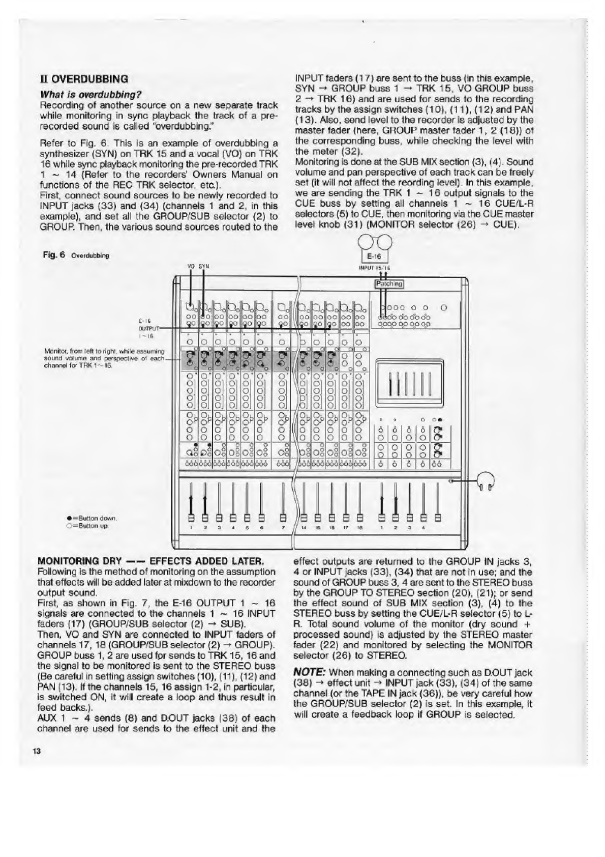
INPUT
faders
(17)
are
sent
to
the
buss
(in
this
example,
SYN
-*
■
GROUP
buss
1
-»
TRK
15,
VO
GROUP
buss
2
-*
TRK
16)
and
are
used
for
sends
to
the
recording
tracks
by
the
assign
switches
(10),
(11},
(12)
and
PAN
(13).
Also,
send
level
to
the
recorder
is
adjusted
by
the
master
fader
(here,
GROUP
master
fader
1,2
(18})
of
the
corresponding
buss,
while
checking
the
level
with
the
meter
(32).
Monitoring
is
don
eat
the
SUB
MIX
section
(3),
(4).
Sound
volume
and
pan
perspective
ot
each
track
can
be
freely
set
(it
will
not
affecl
the
reording
level).
In
this
example,
we
are
sending
the
TRK
1
-
?6
oulpul
signals
to
the
CUE
buss
by
setting
all
channels
1
~
16
CUE/L-R
selectors
(6)
to
CUE,
then
monitoring
via
the
CUE
master
level
knob
(31)
(MONITOR
selector
(26)
-
CUE).
H
OVERDUE
BING
What
Is
ovsrdubbing?
Recording
of
another
source
cn
a
new
separate
track
■
while
monitoring
in
sync
playback
the
track
of
a
pre¬
recorded
sound
is
called
"cverdubbing,'
1
Refer
to
Fig.
6.
This
is
an
example
of
overdubbing
a
synthesizer
(SYN)
on
TRK
15
and
a
vocat
(VO)
on
Trk
16
while
sync
playback
monitoring
the
pre-recorded
TRK
1
-
14
(Refer
to
the
recorders'
Owners
Manual
on
functions
of
the
REC
TRK
selector,
etc.).
First,
connect
sound
sources
lo
be
newly
recorded
to
INPUT
jacks
(33)
and
(34)
(channels
1
and
2,
in
this
example),
and
set
all
the
GROUP'SUB
selector
(2)
to
GROUP.
Then,
the
various
sound
sources
routed
to
the
Fig.
6
Cven.li/r:birig
too
10-0
L-lli
OUlPlJT'
I
-
I
ft
Monitor
town
left
ta
righs
wftiitf
assuming
SCn-rid
rfjiiB
sinsd
prtf!ipcic-1i^
Ch^ngl
fcf
TFK
1-
lG,
a.-:
c
:m
*
=
Sudan
down.
=
(ktlgn
:.p.
MONITORING
DRY
--EFFECTS
ADDED
LATER,
Following
is
the
method
of
monitoring
on
the
assumption
that
effects
will
be
added
later
at
mixdown
to
the
recorder
output
sound.
First,
as
shown
in
Fig.
7,
the
E-16
OUTPUT
1-16
signals
are
connected
to
the
channels
1
~
16
INPUT
faders
(17)
(GROUP/SUB
selector
(2)
-
SUB),
Then,
VO
and
3YN
are
connected
to
INPUT
faders
of
channels
17,
16
(GROUP/SU8
selector
(2)
-
►
GROUP).
GROUP
buss
1.
2
are
used
for
sends
to
TRK
15,
16
and
the
signal
to
be
monitored
is
sent
to
the
STEREO
buss
(Be
careful
in
setting
assign
switches
(10),
(11),
(12)
and
PAN
(13),
It
the
channels
15,
16
assign
1-2,
in
particular.
Is
switched
ON,
it
will
create
a
loop
and
thus
result
in
feed
backs.).
AUX
1
~
4
sends
(6)
and
D.OUT
jacks
(39}
of
each
effect
outputs
are
returned
to
the
GROUP
IN
jacks
3,
4
or
JNPUT
jacks
(33),
(34)
that
are
not
in
use;
and
the
sound
of
GROUP
buss
3,
4
are
sent
to
the
STEREO
buss
by
the
GROUP
TO
STEREO
section
(20),
(21);
or
send
the
effect
sound
of
SUB
MIX
section
(3),
(4)
to
the
STEREO
buss
by
setting
the
CUE/L-R
selector
(5)
to
L-
R.
Total
sound
volume
of
the
monitor
(dry
sound
+
processed
sound)
is
adjusted
by
the
STERE-O
master
fader
(22)
and
monitored
by
selecting
the
MONITOR
selector
(26)
to
STEREO.
NOTE:
When
making
a
connecting
such
as
D.OUT
jack
(38)
-*
■
effect
unit
-*INPUT
jack
(33),
(34)
of
the
same
channel
(or
the
TAPE
IN
jack
(36)),
be
very
careful
how
the
GROUP/SUB
selector
(2)
is
set.
In
this
example,
it
will
create
a
feedback
loop
it
GROUP
is
selected.
channel
are
used
few
sends
to
the
effect
unit
and
the
13

HI.
PING-PONG
RECORDING
What
is
ping-pong
recording?
Combining
the
Payback
sounds
of
a
multiple
number
of
pre-recorded
tracks
by
a
mixer,
[hers
recording
the
mixed
signal
onto
another
track
is
called
"ping-pong
recording,"
This
is
a
very
convenient
method
when
a
number
of
sound
sources
must
be
recorded
onto
a
limited
number
or
tracks
as
ping-pong
recording
allows
overdubbing
new
sound
sources
over
the
old
tracks.
Refer
to
Fig.
8,
This
is
an
example
of
stereo
mixing
with
this
mixer
the
output
signals
of
the
E
-16
TRK
1
-
7
(the
basic
tracks
of
the
above
example)
and
ping-pong
recording
on
TRK
15
and
TRK
16.
GROUP
buss
1
and
2
were
used
Far
sends
to
the
recorder
at
overdubbing
(Refer
to
Fig.
2)
out
here,
let's
consider
using
the
STEREO
buss.
The
GROUP
buss,
of
course,
can
be
used
but
as
more
input
sources
can
be
mixed
by
using
the
STEREO
buss,
this
is
especially
advantageous
during
ping-ponc
recording,
the
reason
for
this
is
in
the
fact
that
sounds
which
have
been
ping-
pong
recorded
cannot
be
separately
processed
at
mixdown.
Consequently,
when
ping-pong
recording,
it
is
necessary
to
process
the
tracks
brforc
they
are
sent
to
the
recording
track.
Thus,
the
buss
which
allows
mixing
more
effect
returns
will
be
better
First,
output
signals
of
TRK
1
-
7
are
connected
to
the
Channels
1
-
7
INPUT
faders
{17)
(GROUP/SUB
selector
(2)
-*
■
SUB).
Then,
these
signets
are
sent
to
the
STEREO
buss
by
the
assign
L-R
switch
(12)
and
PAN
(13),
and
further,
sent
via
(ho
STEREO
master
fader
(23)
to
TRK
15,
16
from
the
STEREO
OUT
jack
1
(43).
Tor
monitoring
the
TRK
15,
16
output
signals
are
sen!
to
SUB
MiX
sections
(3),
(4)
(GROUP/SUB
selector
(2)
-*
GROUP),
and
the
CUE
buss
is
monitored
by
setting
the
CUE/L-R
selector
(5)
to
CUE
(CUE
master
level
knoh
(31)
->
raise
Fever;
MONITOR
selector
(26)
-
CUE).
For
effect
processing,
D,OUT
jack
(38)
and
AUX
1
~
4
sends
(8)
are
used.
The
relurns
from
D.OUT
jack
(33)
is
connected
to
INPUT
jacks
(33),
(34)
of
the
same
channel,
sound
volume
and
perspective
determined
at
the
SUB
MIX
sections
(3)
and
(4),
then
sent
to
the
STEREO
buss
by
the
C
U
E/L
-R
selector
(5)
Effect
returns
from
the
AUX
OUT
jacks
1
~
4
(39)
are
connected
to
the
channels
15-16
INPUT
jacks
(33)
and
(34),
each
sound
volume
adjusted
by
the
INPUT
fader
(17),
the
perspectives
set
by
the
assign
L-R
switch
(
1
2
)
and
PAN
(13),
then
sent
to
toe
STEREO
buss.
Effect
sound
timbre
is
adjusted
by
EG
(7).
When
ping-pong
recording
by
this
method,
be
careful
in
selecting
I
he
GROUP/SUB
selector
(2)
for
channels
1
~
7
and
15,
16,
in
addition
to
precautions
In
the
schematic.
If
these
selections
are
made
in
reverse,
it
will
create
a
loop
between
the
effect
INyOUT
and
between
IN,'OUT
of
TRK
15,
16,
and
could
result
in
feedback.
14
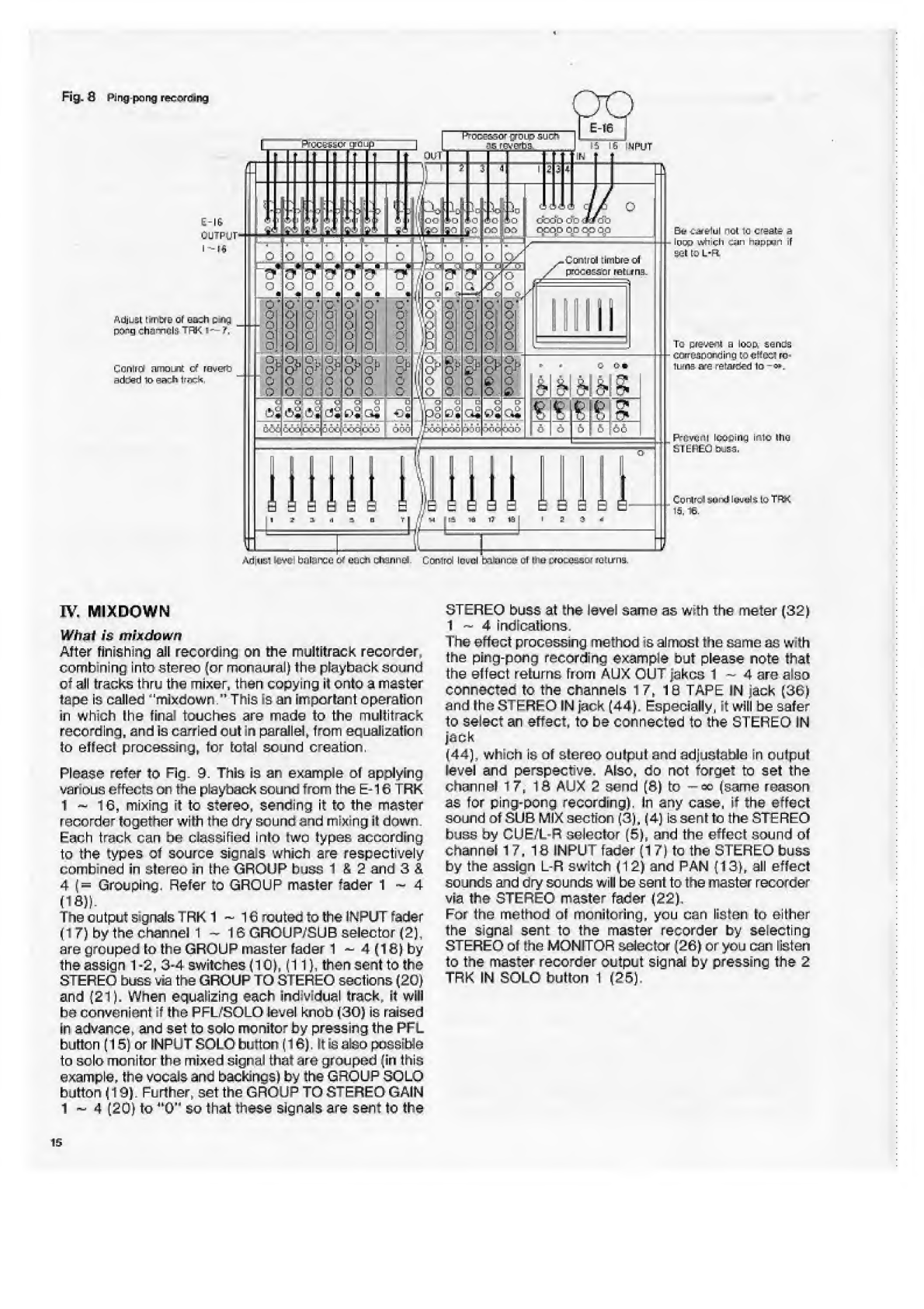
pong
rtewieang
OCEHCF
STOIC
15
IG
NPUT
E-lt
ouipgp
Eii-
Latlul
noi
ia
create
a
loop
tjiicli
-:ypnan
iF
set
to
L-R
.tofiirca
timbre
of
pfi^:a:a'ur
returns.
ftdjuEL
!.-M>cre
ol
oa:h
:
r
r
-
pocig
chnmcIS-TFK
1"^7ii
Ta
preuwtf
a
loopi
aands
CoiTusnKWJirtg
Ki
cKcol
re
luma-are
retard
lo
-
os.
Conlrri
amoLft
of
raueft*
ad3eti
lo
eachlrw*.
prfivtifll
loe-pirim
ifilo
the
aFtl^BObtjsa.
•Viiuiil
sl'w;
b;ilance
of
each
channel.
Corclrd
IomcI
baBmue
or
i?tu
i^oeeasoi
icnurns.
STEREO
buss
at
the
level
same
as
with
the
meter
(32)
1
~
4
indications.
The
effect
processing
method
is
almost
the
same
as
with
the
ping-pong
recording
example
but
please
note
that
the
effect
returns
from
AUX
OUT
Jakes
1
-
A
are
also
connected
to
the
channels
17,
IB
TAPE
IN
jack
(36)
and
ihe
STEREO
IN
jack
(44),
Especially,
it
will
be
safer
to
select
an
effect,
to
be
connected
to
the
STEREO
IN
jack
(44),
which
is
of
stereo
oulput
and
adjustable
in
oulput
level
and
perspective.
Also,
do
not
forget
to
set
the
channel
T
7,
1
(1
AUX
2
send
(6)
to
-
«>
(same
reason
as
for
ping-pong
recording).
In
any
case,
if
the
effect
sound
of
SUB
MIX
section
(3),
(4)
is
sent
to
the
STEREO
buss
by
CUE/L-R
selector
(5),
and
the
effect
sound
of
channel
17,
IS
INPUT
fader
{17)
to
the
STEREO
buss
by
the
assign
L-R
switch
(12)
and
PAN
(13),
all
effect
sounds
and
dry
sounds
wiH
be
sent
to
the
master
recorder
via
the
STEREO
master
fader
(22).
For
the
method
of
monitoring,
you
can
listen
lo
either
the
signal
sent
to
the
master
recorder
by
selecting
STEREO
Df
the
MONITOR
selector
(26)
or
you
can
listen
to
the
master
recorder
output
signal
by
pressing
the
2
TRK
IN
SOLO
button
1
(25),
IV.
MIXDQWN
Whai
is
mixdown
After
finishing
all
recording
on
the
muititrack
recorder,
combining
into
stereo
(or
monaural)
the
playback
sound
ot
all
tracks
thru
the
mixer,
then
copying
it
onto
a
master
tape
is
called
''mljidown"
This
is
an
important
operation
in
which
!he
frnai
touches
are
made
to
the
multitrack
recording,
end
is
carried
out
in
parallel,
from
equalization
to
effect
processing,
for
total
sound
creation.
Please
refer
to
Fig.
3.
This
ie
an
example
ol
applying
various
effects
on
the
playback
sound
from
the
E
-16
TRK
1
-
16,
mixing
it
to
stereo,
sending
it
to
the
master
recorder
together
with
trie
dry
sound
end
mixing
it
down.
Each
track
can
bo
classified
into
(wo
types
according
to
the
types
ol
source
signals
which
are
respectively
combined
in
stored
in
the
GROUP
buss
1
£
2
and
3
&
4
(=
Grouping.
Refer
to
GROUP
master
fader
1-4
(IS))
The
output
signals
1RK
1
—
16
routec
to
the
INPUT
rader
(17)
by
the
channel
1—16
GROUP/SUB
selector
(2),
are
grouped
lo
the
GROUP
master
fader
1
-
4
(16)
by
the
assign
1-2,
3-4
switches
(10).
(11).
then
sent
to
the
STEREO
buss
via
the
GROUP
TO
STEREO
sections
(20)
and
(21).
When
equalising
each
individual
track,
it
will
be
convenient
it
the
PFL/SOLO
level
knob
(30)
is
raised
in
advance,
and
set
to
solo
monitor
by
pressing
the
PFL
button
(15}
or
INPUT
SOLO
button
(16),
It
is
also
possible
to
solo
monitor
the
mixed
signal
that
are
grouped
-iri
Ibis
example,
the
vocals
and
backings)
by
the
GROUP
SOLO
button
(19).
Further,
set
the
GROUP
TO
STEREO
GAIN
1
~
4
(20)
to
"O'
1
So
that
these
signals
are
sent
to
the
i
3
■
1
<4
p
c
5
i
\o
‘HI
ip
_
L_
0
o
c
P-.V
■
y
■■
.6
c
r>
■
c
C
■
c
o
o
<
0
o
C
c
O'
£
c
of
C
o^c
0
£
£
0
5
c
J
c
€3
-
■
j-,
G
*
-t*
trii
£
t-H
V
,
0
0
■
fj*
0
0
m
0
0.
0
0
o
0
0
o
1
n';
oj
o
o
o
/p!
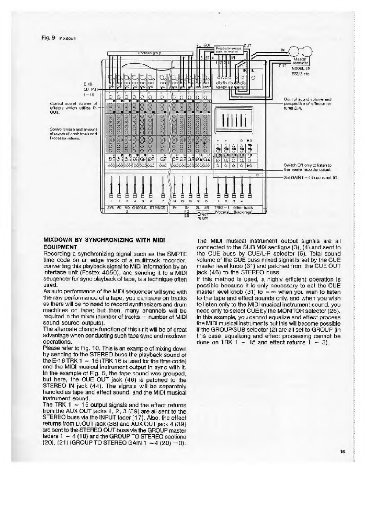
Fig,
9
Ml*
d
o
wn
MIXDOWN
BY
SYNCHRONIZING
WITH
MIDI
EQUIPMENT
Recording
a
synchroni
2
izig
signal
such
as
the
SMPTE
time
code
cm
an
edge
track
of
a
multitrack
recorder,
converting
this
playback
signal
to
MIDI
information
by
an
interface
unit
(Fostex
4050),
and
sanding
it
to
a
MIDI
eeuqencer
for
sync
playback
of
tape,
is
a
technique
often
used,
Ac
auto
performance
of
the
MIDI
sequencer
will
sync
with
the
raw
performance
of
a
tape,
you
can
save
on
tracks
as
there
will
be
no
need
to
record
synthesizers
and
drum
machines
on
tape;
but
then,
many
channels
wilt
be
recfuirec
In
the
mixer
(number
of
tracks
-
r
umber
of
MIDI
sound
source
outputs).
The
alternate
change
funclion
of
this
unit
will
be
ot
great
advantage
when
conducting
such
tape
sync
and
mixdown
operations.
Please
refer
to
Fig.
10.
This
is
an
exanple
of
mixing
down
by
sending
to
the
STEREO
buss
I
he
playback
sound
of
the
E-16
TRK
1
~
15
(TFK
16
is
used
for
the
time
code)
and
the
Mini
musical
Instrument
output
in
sync
with
it.
In
the
example
of
Fig,
5,
the
tape
sound
was
grouped,
but
here,
the
CUE
OUT
jack
(46)
is
patched
to
the
STEREO
IN
jack
(44).
The
signals
will
he
separately
handled
as
tape
and
effect
sound,
and
the
MIDI
musical
instrument
sound.
The
TRK
1
~
15
output
signals
and
the
effect
re!urns
from
the
AUX
OUT
jacks
1.2,
3
(39)
are
all
sent
to
the
STEREO
buss
via
the
INPUT
fader
(17).
Also,
the
effect
returns
from
D,OUT
jack
(30)
ana
AUX
OUT
jack
4
(39)
are
sent
to
the
STEREO
OUT
buss
via
the
GROUP
master
faders
1
~
4
(18)
and
the
GROUP
TO
STEREO
seclions
(20),
(2
T)
(GROUP
TO
STEREO
GAIN
1
~
4
(20)
->0).
The
MIDI
musical
instrument
output
signals
are
all
connected
to
the
SUB
MIX
sections
(3),
(4)
and
sent
to
the
CUE
buss
by
CUE/L-R
selector
(5),
Total
sound
volume
Of
the
GUE
buss
mixed
signal
is
Set
by
the
CUE
master
level
knob
(31)
and
palched
from
the
CUE
OUT
Jack
(46)
to
the
STEREO
buss,
if
this
method
is
used,
a
highly
efficient
operation
is
possible
because
4
Is
only
necessary
In
set
the
GUE
master
level
knob
(31)
to
-
«?
when
you
wish
to
listen
to
the
tape
and
effect
sounds
only,
and
when
you
vwsh
to
listen
only
to
the
MIDI
musical
instrument
sound,
you
need
only
to
select
CUE
by
the
MONITOR
selector
(2GJ.
In
this
example,
you
cannot
equalize
and
eifect
process
!he
MIDI
musical
instruments
but
th»s
will
become
possible
if
the
GROUP/SUB
selector
(2)
are
all
set
to
GROUP
(In
lhi$
case,
equalizing
and
effect
processing
cannot
be
done
on
TRK
1-15
and
effect
returns
i
~
3),
16

Fig.
10
Ta-pa
fiyne
irirndowfl
SECTION
7,
OTHER
METHODS
OF
OPERATION
A
wide
variety
of
controlling
from
sound
reinforcement
by
the
main
speaker
to
monger
sends
to
lire
stage
and
effect
processing
are
possible
when
This
mi
war
is
used
as
&
PA
system
mixer
in
smaN
auditoriums
and
clubs.
In
the
example
of
Fig.
11
n
the
outputs
of
the
musical
in¬
struments
are
grouped
?nto
(A)
and
{BJ.
then
sent
bo
the
main
speakers
through
1h@
GROUP
TO
STEREO
sections
(20)
and
(21).
AUX
3,
4
sends
(0)
are
used
for
sends
to
the
processor
and
AUX
1,
2
sends
(8}
are
used
for
2
channel
stage
monitor
sends
(PRE/POST
selector
(9)
PRE).
In
addition,
mixed
signals
of
CD,
cassette
deck,
effect
outputs,
etc.
are
sent
by
patching
the
CUE
OUT
jack
(46)
to
the
GROUP
buss
1,
2
and
mixed
into
group
(A).
The
main
speaker
sound
volume
is
adjusted
by
the
STEREO
master
fader
(22),
and
total
sound
volume
of
the
monitor
send,
by
the
AUX
master
GAIN
1
and
2
(23).
17

SECTION
8.
TROUBLE
SHOOTING
When
this
mixer
fails
to
operate
properly,
check
the
following
before
concluding
there
is
a
breadkdown
or
malfunction.
•
Feedback
occurs
when
a
given
track
is
set
to
input
monitor.
Are
you
sure
the
output
of
the
given
track
is
not
connected
to
the
buss
which
is
used
for
the
send
to
this
track?
Check
the
signal
routing
determined
by
the
assign
switches
(10),
(11),
(12)
and
PAN
(13),
or
that
of
CUE/L-R
selector
(5)
to
see
that
you
are
not
creating
a
loop.
•
No
signal
is
heard
at
the
INPUT
fader
(17).
Are
you
sure
you
are
not
plugging
a
monaural
phone
plug
into
the
SEND/RCV
jack
(37)
for
that
channel?
If
so,
the
signal
will
be
sent
to
the
processor
but
the
effect
output
will
not
be
received.
•
Cannot
hear
the
signal
selected
by
the
MONITOR
selector
(26).
Meter
(32)
L,
R
does
not
indicate
properly.
Are
you
sure
the
PFL/SOLO
LED
(48)
is
not
lit?
If
so,
refer
again
to
“NAME
AND
FUNCTION/OPERATION
OF
EACH
CONTROLS
AND
SWITCHES”
in
page
4.
•
CUE
is
selected
by
MONITOR
selector
(26)
but
no
sound
is
heard.
Also
can
not
hear
the
PFL
and
SOLO
sounds.
Are
the
CUE
master
level
knob
(31)
and/or
the
PFL/SOLO
level
knob
(30)
raised?
Are
the
MONITOR
level
knob
(28)
and
PHONES
level
knob
(29)
raised?
Check
these
again.
•
No
sound
from
the
speaker.
Is
the
MONITOR
OUT
selector
(27)
properly
selected?
Check
this
again.
•
Even
though
the
MUTE
button
(14)
is
pressed,
sound
from
this
channel
is
heard.
Are
you
sure
the
PFL
button
(15)
is
not
pressed
or
the
PRE
signal
of
AUX
1,
2
send
(8)
is
not
solo
monitored
by
the
AUX
SOLO
button
1,
2
(24)?
Mute
is
effective
only
on
the
signals
immediately
after
the
INPUT
faders
(17).
•
Although
sound
is
faded
out
by
the
INPUT
fader
(17),
the
processed
effect
sound
of
this
channel
is
still
heard.
Are
you
sure
that
AUX
1,
2
and
(8)
is
not
used
for
sending
to
the
processor
and
also
that
PRE/POST
selector
(9)
is
not
set
to
PRE?
Set
to
POST
if
you
wish
to
link
it
with
the
fader.
•
PEAK
LED
is
frequently
lit
although
level
had
been
malched
by
TRIM
(1).
Did
you
raise
the
EQ
(7)
gain
for
timbre
adjusting
after
level
matching?
If
so,
refer
again
to
“2.
Level
Match¬
ing
With
External
Equipment”
in
page
7.
•
Sound
not
assigned
to
STEREO
buss
is
in
the
STEREO
buss
monitor.
Are
you
sure
the
GROUP
TO
STEREO
GAIN
1
-
4
is
not
raised?
Set
this
to
-
<»
when
it
is
not
required.
SECTION
9.
NOTES
ON
AFTER
SERVICE
1.
A
warranty
card
is
attached
to
this
product.
As
the
proper
items
in
the
warranty
card
are
filled
in
at
the
4.
point
of
purchase,
check
these
items
and
carefully
store
it
together
with
Owners
Manual.
2.
The
warranty
period
is
one
year
from
date
of
purchase
5.
Throughout
the
warranty
period,
the
Service
Section
of
our
organization
will
repair
the
product
in
accordance
to
content
of
the
warranty.
Refer
to
the
warranty
card
for
details.
3.
Please
consult
your
store
of
purchase,
nearest
R»stex
Office
or
the
Service
Department
in
the
Fostex
head
office
if
you
have
any
questions
on
repairs
after
expiration
of
the
warranty
period
or
if
the
warranty
card
cannot
be
produced.
If
performance
of
the
product
can
be
maintained
by
repairing,
it
will
be
repaired
at
cost
by
request
from
the
user
although
the
warranty
has
expired.
Minimum
period
of
stocking
of
maintenance
and
repair
parts
(parts
necessary
for
maintaining
the
function
of
the
product)
for
this
product
is
six
years
after
discontinuation
of
the
product.
This
period
is
determined
by
the
Ministry
of
Commerce
and
Industry.
Addresses
and
telephone
numbers
of
Fostex
Business
Offices
are
listed
on
the
back
cover
of
this
Manual.
18

SECTION
10.
1240/1840/2440
SPECIFICATIONS
INPUT
(x12
by
1240,
x18
by
1840,
x24
by
2440)
Mic
impedance
3kG
or
less
Input
7kfi
baJanced
XLR
connector
and
16kfi
unbalanced
phone
jack
Nominal
input
level
-60dBV(1mV)-10dBV(0.3V)
Minimum
input
level
-
70dBV(0.3mV)
Maximum
input
level
+15dBV(5.6V)
TAPE
INPUT
(x
12
by
1240,
x18
by
1840,
x
24
by
2440)
Input
impedance
20kfl
Nominal
input
level
-10dBV(0.3V)
Minimum
input
level
-
20dBV(0.1V)
Maximum
input
level
+
25dBV(17.8V)
GROUP
BUSS
INPUT
(x4)
and
MASTER
BUSS
INPUT
(L,R)
Input
impedance
20kft
Nominal
input
level
-10dBV(0.3V)
GROUP
OUTPUT
(x
4)
Output
load
impedance
lOktt
or
high
Nominal
output
level
-
10dBV(0.3V)
Maximum
output
level
+15dBV(5.6V)
AUX
OUTPUT
(x4)
AND
CUE(L^R)
OUTPUT
Output
load
impedance
lOkfi
or
high
Nominal
output
level
-10dBV(0.3V)
Maximum
output
level
+
15dBV(5.6V)
STEREO
OUTPUT
(L,R)
Output
load
impedance
lOkft
or
high
Nominal
output
level
-
10dBV(0.3V)
Maximum
output
level
+
15dBV(5.6V)
STEREO
OUTPUT
(L,R)
(Phone
jack)
Output
load
impedance
lOkil
or
high
Nominal
output
level
+
2dBV(1.26V)
Maximum
output
level
+
15dBV(5.6V)
MONITOR
OUTPUT
(L,R)
Output
load
impedance
10kQ
or
high
Nominal
output
level
-
10dBV(0.3V)
Maximum
output
level
+15dBV(5.6V)
HEADPHONE
OUTPUT
Output
load
impedance
8-400
Maximum
output
.
lOOmW
DIRECT
OUTPUT
(1240-
x
12,
1840-
x
18,
2440-
x
24)
Output
load
impedance
lOkO
Maximum
output
level
+
15dBV
FREQUENCY
RESPONCE
Input
(Mic)
20
-
20kHz
+
1
/
-
2dB
Line
20~20kHz
+1/-1.5dB
Headphone
30
-
20kHz
+1/
-
2dB
EQUIVALENT
INPUT
NOISE
Input
(Mic)
-
125dB
unweighted
(20-
20kHz)
-126dB
weighted
(IEC/ANSI)
OVERALL
SIGNAL
TO
NOISE
One
mic
input
12
mic
input
18
mic
input
24
mic
input
T.H.D
66dB
weighted,
65dB
unweighted
52dB
weighted,
51
dB
unweighted
50dB
weighted,
49dB
unweighted
48dB
weighted,
47dB
unweighted
0.05%
at
1kHz
nominal
level
Headphone
0.1%
at
1kHz
100mW/400
FADER
ATTENUATION
70dB
at
1kHz
CROSSTALK
65dB
at
1kHz
PARAMETRIC
EQUALIZER
60<~>1kHz
+
15/-15dB
400<-6kHz
+15/-15dB
10kHz
+15/-15dB
POWER
REQUIRMENTS
1240
1840
2440
DIMENSIONS
1240
1840
2440
WEIGHT
1240
1840
2440
33W
37W
45W
120(H)x860(W)x820(D)mm
120(H)x1135(W)x820(D)mm
120(H)x1410(W)x820(D)mm
24kg
(53
lbs)
32
kg
(70
lbs)
40kg
(88
lbs)
Other manuals for 1240
1
This manual suits for next models
2
Table of contents
Other Fostex Music Mixer manuals


