1-3
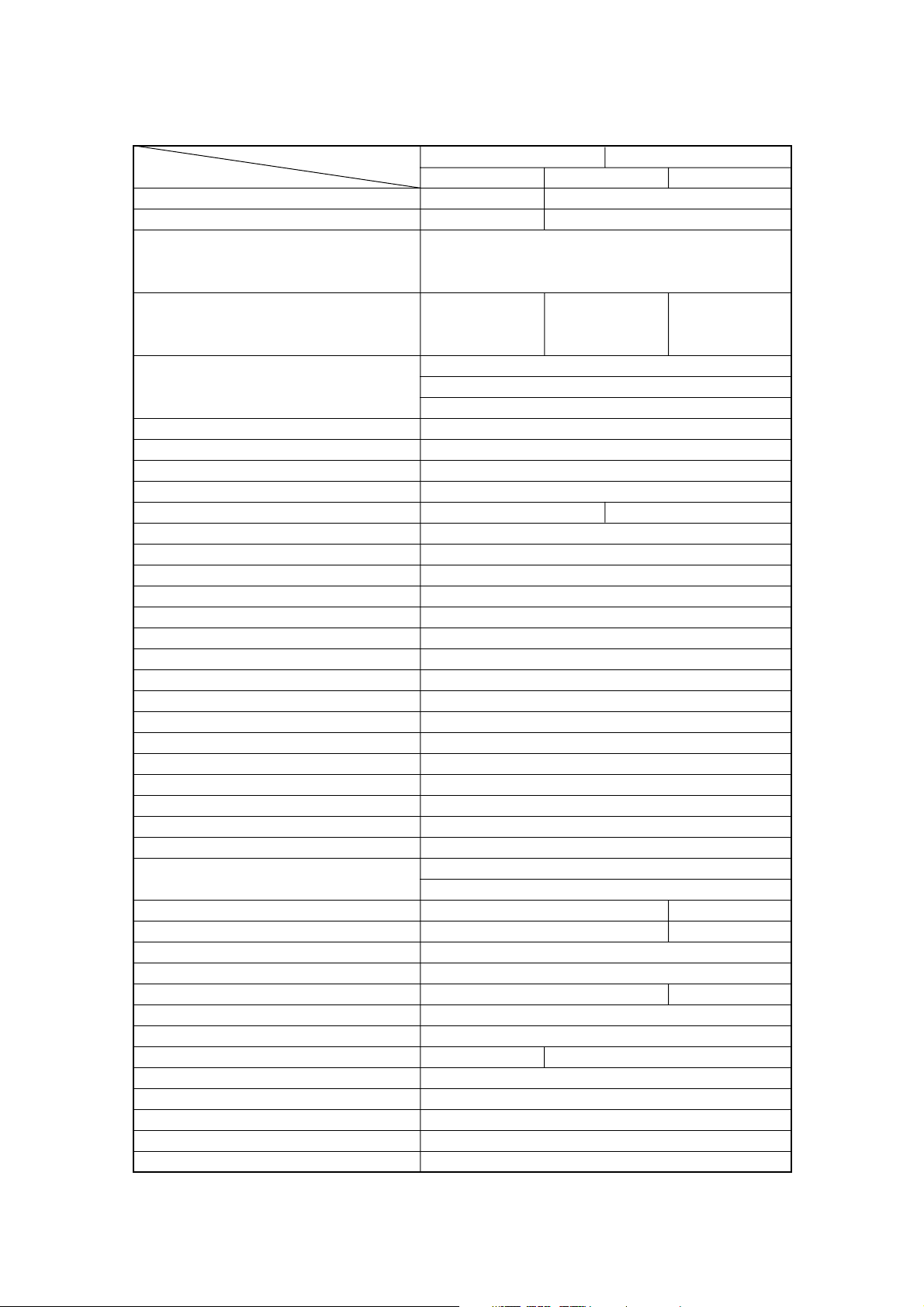
1. Specifications Table
MODEL 40A 50A
Item EPTO EFTO EFO
Overall length (approx.) 630 mm (24.8 in) 1120 mm (44.1 in)
Overall width (approx.) 345 mm (13.6 in) 384 mm (15.1 in)
Transom (S) 1227 mm (48.3 in)
Overall height Transom (L) 1354 mm (53.3 in)
(approx.) Transom (UL) 1481 mm (58.3 in)
Transom (S) 95.5 kg (211 lb) 98.5 kg (217 lb) 88.5 kg (195 lb)
Weight Transom (L) 96.5 kg (213 lb) 99.5 kg (219 lb) 89.5 kg (197 lb)
(approx.) Transom (UL) 99.0 kg (218 lb) 102.0 kg (225 lb) 92.0 kg (203 lb)
Transom (S) 403 mm (15.9 in)
Transom length Transom (L) 530 mm (20.9 in)
(outboard) Transom (UL) 657 mm (25.9 in)
Engine type 3-cylinder inline
Piston displacement 697ml (42.5 cu.in)
Bore & stroke 68 mm (2.68 in) x 64 mm (2.52 in)
No. of cylinders 3
Maximum output 29.4 kW 36.8 kW
Full-throttle range 5150~5850 rpm
Trolling 700 rpm
Idling 700 rpm
Full-throttle fuel consumption (approx.) 17 L/Hr (4.5 US gal/Hr)
Starting system Electric starter motor
Intake system Reed valve
Scavenging system 5-port loop
Exhaust system Through hub
Lubrication system Auto-mixing
Cooling system Forced water-cooling
Water temp. control Thermostat
Ignition system L-CDI
Ignition timing control Electronically advanced
Firing order 1-2-3
Sparkplug Champion RC10ECC
Alternator 12V 280W
Battery 12V 100AH
12V 120AH (0°C or low)
Trim angle 8°~24° 4°~24°
Trim angle settings 5 6
Maximum tilt-up angle 75°
Transom board thickness 31~70 mm (1.22 ~ 2.76 in)
Maximum steering angle 70° 80°
Gear shift Dog clutch (F-N-R)
Gear ratio 1.85 : 1 (13 : 24)
Throttle control Remote-control Tiller handle
Fuel tank 25L (6.60 US gal)
Oil tank 2L (2.1 US qt)
Fuel Unleaded regular gasoline
Engine oil Genuine engine oil or TC-W, 2-stroke marine outboard oil*
Gear oil Genuine gear oil (500 ml) or API GL5, SAE #80
*: Only those products that have been approved.