Tokin TOKINARC TH Series User manual

InstructionManual
CO2MAGWeldingTorches
CO2MAGWeldingTorches
1509 Okubo-cho, Nishi-ku, Hamamatsu-shi,
Shizuoka Japan 432-8006
TEL : +81-53-485-5252 FAX : +81-53-485-5680
E-mail [email protected]
URL http://www.tokinarc.co.jp
Please read this instruction manual
before using the product.
Please be sure to deliver this instruction manual
to the end user of this product.
TH Series
400amp.
TH-40
TH-40F
TH-40L
TH-40G
Semi-AutomaticTorches
350amp.
TH-35
TH-35K
TH-35F
TH-35L
TH-35G
500amp.
TH-50
TH-50F
TH-50L
550amp.
TH-55

Notesregardingsafety
Contents
........................................................ 2
●Do not use the welding torch in places where flying spatter can cause
flammable materials to ignite.
●Do not use the welding torch near places where flammable gases are present.
●Keep base metals away from flammable materials immediately after welding
as they may have become hot.
●Remove any flammable materials on the other side of ceilings, floors and walls
that are being welded as sparks from welding could cause such materials to
ignite.
●The welding cable should be connected as close as possible to the base metal
being welded, and it should be connected securely.
●Do not weld gas cylinders which still contain gas.
●Do not weld sealed tanks or pipes.
●Keep a fire extinguisher close by the place where welding is being carried out
in case a fire starts.
CAUTION Wear protective equipment at all times to protect
yourself and others against arc beam, welding flashes,
flying spatter and slag, and noise.
CAUTION
CAUTION Be sure to observe the following to avoid fires,
explosions and rupturing.
CAUTION Use protective equipment at all times to protect
yourself and others against any fumes and gases that
may be generated from welding.
Be sure to observe the following to avoid burns
from the nozzle and tip or injury from fine wire
ends.
●Always wear protective goggles or welding masks which have sufficient
shielding properties when doing welding or when observing welding being
done.
●Wear protective glasses to protect the eyes from spatter and slag.
●Hang a curtain around the area where welding is being carried out to prevent
welding flashes from affecting passers-by.
●Wear protective clothing such as leather gloves, longsleeves, leg
covers and a leather apron for protection while welding.
●Wear noise proof ear protectors if the noise level is too high.
●Inspections and maintenance should be carried out at periodic intervals, and
the equipment must not be used until any damaged parts found have been
repaired or replaced.
●Do not use cables that are damaged or that have exposed conductors, or that
are rated lower than the specified level.
●Make sure that the cable is connected securely and that it is insulated.
●Welding cable should be connected as close as possible to the base metal
being welded and it should be connected securely.
●Do not wear gloves which are torn or wet.
●Use a safety strap if welding in raised places.
●Turn OFF all power switches and the input power supply when not using.
*Welding flashes contain harmful ultraviolet and infrared lights which can cause
inflammation or burn to eyes.
*Flying spatter and slag can hurt the eyes and cause serious burns.
*The noise generated by welding can cause problems with hearing.
*Fumes and gases are generated when welding is carried out. Inhaling fumes
and gases can be dangerous to your health.
*Welding in confined spaces can reduce the oxygen content in the air, which
can result in suffocation.
●To provent gas poisoning and suffocation, always use a proper ventilation
equipment to vent gases locally or entirely as stipulated by labor safety
regulations and air contamination prevention regulations, or use an adequate
breathing apparatus.
●When welding in a confined space, make sure that the air is circulating freely,
wear some kind of breathing apparatus, and work only under the supervision
of a properly trained supervisor.
●Toxic gases may be generated if welding is carried out near where degreasing,
cleaning or demisting operations are also being carried out. Avoid welding near
places where such operations are being carried out.
●Welding metal which has been plated with zinc will cause toxic fumes. Remove
the plating before welding, or wear adequate absorption equipment for
protection.
*The nozzle or contact tip becomes very hot after use, and it can cause serious
burns if touched.
●Do not touch the nozzle or tip immediately after welding has been completed.
●Do not bring the tip of the welding torch close to your face during wire inching.
*Fires can be caused by spatter and base metals which are hot after welding.
*Fire can occur as a result of heat generated by the flow of current if the cable
has not been correctly connected or there is an incomplete contact in the
current path at the base metal being used.
*Explosions can occur if an arc is generated near containers that contain
flammable substances such as gasoline.
*Ruptures can occur if welding sealed objects such as tanks and pipes.
In the above definitions, ''severe injury'' refers to cases of blindness, physical
wounds, burns (high- and medium-temperature), electric shocks, fractures or
poisoning which may leave scars or lasting ill-effects and for which medical
treatment or prolonged hospitalization may be necessary. ''Injury refers to cases
of physical wounds, burns and electric shocks for which prolonged medical
treatment and hospitalization are not necessary, and ''physical damage'' refers
to extensive damage that may result in damaged property or broken equipment.
●Never Torch charged parts such as welding wire, or contact tip while welding
torch is turned ON and operating.
●Grounding of welding power supply case and base metal and tools which are
connected electrically to the base metal, must be carried out by a qualified
electrician in accordance with the proper electrical engineering regulations.
●Turn OFF all input power supplies by turning OFF the switches in the
distribution box before carrying out any inspections or maintenance.
Be sure to read these instructions before using the welding
torch.
●In order to ensure safe operation, this equipment should only be set up,
inspected and maintained by a qualified person, or by someone who has a
through understanding of the welding equipment and who has received
sufficient training in its use.
●In order to ensure safe operation, this equipment should only be operated by
people who have read these instructions throughly and understood their
contents and who have the knowledge and ability to handle the equipment
safely.
●It is recommended that instruction in all aspects of safe operation should be
obtained from institutions snd associations which provide courses in proper
welding techniques taught by qualified welding instructors.
●After reread these instructions, keep them in a safe and easily-accessible
place so that they can be reread at a later date as required.
●Please contact TOKIN CORPORATION or its dealer if there are any unclear
points in this manual. If there are any questions regarding service, contact the
dealer of your purchase or TOKIN CORPORATION. The contact address and
the telephone number are printed on the rear cover of this instructions.
1.Precautions for safety
●Different degrees of personal injury or equipment damage can occur if this
welding torch is used incorrectly. The terms and symbols which appear in the
''NOTES REGARDING SAFETY'' section of these instructions are classified
into three ranks according to the possible degree of danger or injury that each
one warns against.
Symbol Term Definition
DANGER
The instructions which follow this term represent
situations where failure to follow the instructions will
almost certainly result in severe injury or death.
The instructions which follow this term represent
situations where failure to follow the instructions can
possibly result in severe injury or death.
The instructions which follow this term represent
situations where failure to follow the instructions may
result in injury to the operator or physical damage.
WARNING
CAUTION
2.Items that must always be observed for safety
WARNING These items should be observed at all times in order
to prevent the possibility of serious personal injury.
●Welding torches have been designed and manufactured with full consideration
given to safety; however, the warning and cautions given in this ''Notes Regarding
Safety'' section must always be strictly observed during use. If they are not
observed, severe injury or death through misoperation may result.
●Do not unauthorized personal come into the area where welding equipment is
being used.
●When welding equipment is turned ON, it generates a magnetic field. This
magnetic field may adversely affect the operation of some sensors and gauges.
For the same reason, people who are using a heartbeat pace maker must not go
close to operating welding equipment or go into workshops where welding
equipment is being used unless prior medical approval has been obtained.
●In order to ensure safe operation, welding torch, wire feeder and the welding
power supply equipment should only be set up, inspected, maintained and
repaired by a qualified person, or by someone who has a through understanding of
welding equipment and who has received sufficient training in its use.
●In order to ensure safe operation, welding torch should only be operated by people
who have read these instructions and the instructions for the wire feeder and
power supply equipment through and understood their contents and who have the
knowledge and ability to handle the equipment safely.
●Do not use welding torch for any applications other than for arc welding as
explained in these instructions and in the instructions for the wire feeder and power
supply equipment.
*Touching the charged parts can cause fatal electric shocks or burns. Welding
wire, contact tip and tip body are charged whenever the welding torch is
turned ON and operating.
WARNING These items should be observed at all times in order
to prevent the possibility of electric shocks.
Specifications
PreparerationforWelding
WireFeederAdapters
ReplacingtheTorchBody
ReplacingtheInnerTube
ReplacingtheTipBody
..................................................................... 3
.................................................... 3
......................................................... 3
................................................... 4
.................................................... 4
5
.......................................................
ReplacingtheLiner
THMicroSwitchASSY
ReplacingMicroSwitch
PartsList
THSeries
TorchAdapter
Adapter
THArcShield
............................................................. 6
....................................................... 7
....................................................... 7
........................................................................ 8
.................................................................. 8
............................................................................ 8
.................................................................. 8
THTorchHook ................................................................ 8
THSwitchGuard ............................................................. 8
1
Notesregardingsafety
Contents
........................................................ 2
●Do not use the welding torch in places where flying spatter can cause
flammable materials to ignite.
●Do not use the welding torch near places where flammable gases are present.
●Keep base metals away from flammable materials immediately after welding
as they may have become hot.
●Remove any flammable materials on the other side of ceilings, floors and walls
that are being welded as sparks from welding could cause such materials to
ignite.
●The welding cable should be connected as close as possible to the base metal
being welded, and it should be connected securely.
●Do not weld gas cylinders which still contain gas.
●Do not weld sealed tanks or pipes.
●Keep a fire extinguisher close by the place where welding is being carried out
in case a fire starts.
CAUTION Wear protective equipment at all times to protect
yourself and others against arc beam, welding flashes,
flying spatter and slag, and noise.
CAUTION
CAUTION Be sure to observe the following to avoid fires,
explosions and rupturing.
CAUTION Use protective equipment at all times to protect
yourself and others against any fumes and gases that
may be generated from welding.
Be sure to observe the following to avoid burns
from the nozzle and tip or injury from fine wire
ends.
●Always wear protective goggles or welding masks which have sufficient
shielding properties when doing welding or when observing welding being
done.
●Wear protective glasses to protect the eyes from spatter and slag.
●Hang a curtain around the area where welding is being carried out to prevent
welding flashes from affecting passers-by.
●Wear protective clothing such as leather gloves, longsleeves, leg
covers and a leather apron for protection while welding.
●Wear noise proof ear protectors if the noise level is too high.
●Inspections and maintenance should be carried out at periodic intervals, and
the equipment must not be used until any damaged parts found have been
repaired or replaced.
●Do not use cables that are damaged or that have exposed conductors, or that
are rated lower than the specified level.
●Make sure that the cable is connected securely and that it is insulated.
●Welding cable should be connected as close as possible to the base metal
being welded and it should be connected securely.
●Do not wear gloves which are torn or wet.
●Use a safety strap if welding in raised places.
●Turn OFF all power switches and the input power supply when not using.
*Welding flashes contain harmful ultraviolet and infrared lights which can cause
inflammation or burn to eyes.
*Flying spatter and slag can hurt the eyes and cause serious burns.
*The noise generated by welding can cause problems with hearing.
*Fumes and gases are generated when welding is carried out. Inhaling fumes
and gases can be dangerous to your health.
*Welding in confined spaces can reduce the oxygen content in the air, which
can result in suffocation.
●To provent gas poisoning and suffocation, always use a proper ventilation
equipment to vent gases locally or entirely as stipulated by labor safety
regulations and air contamination prevention regulations, or use an adequate
breathing apparatus.
●When welding in a confined space, make sure that the air is circulating freely,
wear some kind of breathing apparatus, and work only under the supervision
of a properly trained supervisor.
●Toxic gases may be generated if welding is carried out near where degreasing,
cleaning or demisting operations are also being carried out. Avoid welding near
places where such operations are being carried out.
●Welding metal which has been plated with zinc will cause toxic fumes. Remove
the plating before welding, or wear adequate absorption equipment for
protection.
*The nozzle or contact tip becomes very hot after use, and it can cause serious
burns if touched.
●Do not touch the nozzle or tip immediately after welding has been completed.
●Do not bring the tip of the welding torch close to your face during wire inching.
*Fires can be caused by spatter and base metals which are hot after welding.
*Fire can occur as a result of heat generated by the flow of current if the cable
has not been correctly connected or there is an incomplete contact in the
current path at the base metal being used.
*Explosions can occur if an arc is generated near containers that contain
flammable substances such as gasoline.
*Ruptures can occur if welding sealed objects such as tanks and pipes.
In the above definitions, ''severe injury'' refers to cases of blindness, physical
wounds, burns (high- and medium-temperature), electric shocks, fractures or
poisoning which may leave scars or lasting ill-effects and for which medical
treatment or prolonged hospitalization may be necessary. ''Injury refers to cases
of physical wounds, burns and electric shocks for which prolonged medical
treatment and hospitalization are not necessary, and ''physical damage'' refers
to extensive damage that may result in damaged property or broken equipment.
●Never Torch charged parts such as welding wire, or contact tip while welding
torch is turned ON and operating.
●Grounding of welding power supply case and base metal and tools which are
connected electrically to the base metal, must be carried out by a qualified
electrician in accordance with the proper electrical engineering regulations.
●Turn OFF all input power supplies by turning OFF the switches in the
distribution box before carrying out any inspections or maintenance.
Be sure to read these instructions before using the welding
torch.
●In order to ensure safe operation, this equipment should only be set up,
inspected and maintained by a qualified person, or by someone who has a
through understanding of the welding equipment and who has received
sufficient training in its use.
●In order to ensure safe operation, this equipment should only be operated by
people who have read these instructions throughly and understood their
contents and who have the knowledge and ability to handle the equipment
safely.
●It is recommended that instruction in all aspects of safe operation should be
obtained from institutions snd associations which provide courses in proper
welding techniques taught by qualified welding instructors.
●After reread these instructions, keep them in a safe and easily-accessible
place so that they can be reread at a later date as required.
●Please contact TOKIN CORPORATION or its dealer if there are any unclear
points in this manual. If there are any questions regarding service, contact the
dealer of your purchase or TOKIN CORPORATION. The contact address and
the telephone number are printed on the rear cover of this instructions.
1.Precautions for safety
●Different degrees of personal injury or equipment damage can occur if this
welding torch is used incorrectly. The terms and symbols which appear in the
''NOTES REGARDING SAFETY'' section of these instructions are classified
into three ranks according to the possible degree of danger or injury that each
one warns against.
Symbol Term Definition
DANGER
The instructions which follow this term represent
situations where failure to follow the instructions will
almost certainly result in severe injury or death.
The instructions which follow this term represent
situations where failure to follow the instructions can
possibly result in severe injury or death.
The instructions which follow this term represent
situations where failure to follow the instructions may
result in injury to the operator or physical damage.
WARNING
CAUTION
2.Items that must always be observed for safety
WARNING These items should be observed at all times in order
to prevent the possibility of serious personal injury.
●Welding torches have been designed and manufactured with full consideration
given to safety; however, the warning and cautions given in this ''Notes Regarding
Safety'' section must always be strictly observed during use. If they are not
observed, severe injury or death through misoperation may result.
●Do not unauthorized personal come into the area where welding equipment is
being used.
●When welding equipment is turned ON, it generates a magnetic field. This
magnetic field may adversely affect the operation of some sensors and gauges.
For the same reason, people who are using a heartbeat pace maker must not go
close to operating welding equipment or go into workshops where welding
equipment is being used unless prior medical approval has been obtained.
●In order to ensure safe operation, welding torch, wire feeder and the welding
power supply equipment should only be set up, inspected, maintained and
repaired by a qualified person, or by someone who has a through understanding of
welding equipment and who has received sufficient training in its use.
●In order to ensure safe operation, welding torch should only be operated by people
who have read these instructions and the instructions for the wire feeder and
power supply equipment through and understood their contents and who have the
knowledge and ability to handle the equipment safely.
●Do not use welding torch for any applications other than for arc welding as
explained in these instructions and in the instructions for the wire feeder and power
supply equipment.
*Touching the charged parts can cause fatal electric shocks or burns. Welding
wire, contact tip and tip body are charged whenever the welding torch is
turned ON and operating.
WARNING These items should be observed at all times in order
to prevent the possibility of electric shocks.
Specifications
PreparerationforWelding
WireFeederAdapters
ReplacingtheTorchBody
ReplacingtheInnerTube
ReplacingtheTipBody
..................................................................... 3
.................................................... 3
......................................................... 3
................................................... 4
.................................................... 4
5
.......................................................
ReplacingtheLiner
THMicroSwitchASSY
ReplacingMicroSwitch
PartsList
THSeries
TorchAdapter
Adapter
THArcShield
............................................................. 6
....................................................... 7
....................................................... 7
........................................................................ 8
.................................................................. 8
............................................................................ 8
.................................................................. 8
THTorchHook ................................................................ 8
THSwitchGuard ............................................................. 8
2
Specifications
PreparationforWelding
TorchModel
A
mmφ
m
%( CO2)
%( MAG)
Kg
Kg
TH-40/TH-40F/TH-40L TH-55
450
1.2(1.4,1.6)
3/4/4.5/5/6
60(TypeF:40)
35(TypeF:20)
1.4
3.1
TH-35/TH-35K/TH-35F
TH-35L/TH-35G
350
1.2(0.9,1.0,1.4)
3/4/4.5/5/6
60
35
1.2
2.5
AirCooled
TH-50/TH-50F
TH-50L
500
1.6(1.2,1.4)
3/4/4.5/5/6
60(TypeF:35)
35(TypeF:20)
1.8
3.7
350
1.2(0.8,0.9,1.0)
3
60
35
1.8
3.7
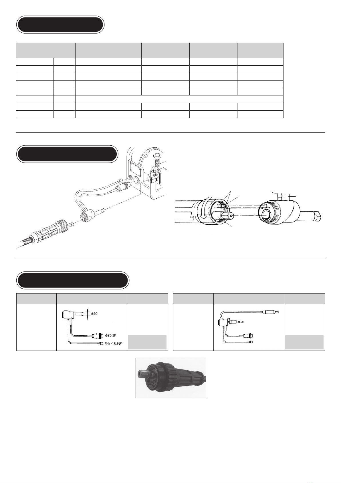
WireFeederAdapters
①Insert the wire feeder adapter electric
supplyfitting,gashose,andswitchcable
intothewirefeeder.
②Nextinsertthetorchadapterelectricsupplyfitting,shieldinggasfitting,
andelectricterminalsintothewirefeederadapter.Besureeverthingis
properlyinsertedbeforefirmlytighteningtheadapternut.
AdapterType ShapeandDimensions Applicable
WireFeeder
NAdapter
(020030)
Panasonic
ForallAirCooled
WireFeeder
NoAdapterisneeded
whenusingaUni-Con
Cseriestorch
AdapterType ShapeandDimensions Applicable
WireFeeder
DAIHEN
CM-231・CM-144
CML-23・CM-501
DAdapter
350A
(020029)
500A
(020031)
EURODirectConnection
RatedCurrent
WireSize
CableLength
DutyCycle
CoolingMethod
ApparentWeight
TotalWeight
ElectricTerminals
ShieldingGasFitting
GasHose
SwitchPlug
ElectricSupplyFitting
Powercableadapter
φ25-2P
9
/16-18UNF
Guideadapter
Outletguide
TorchAdapter WireFeederAdapters
NoAdapterisneeded
whenusingablue
torch
3
Specifications
PreparationforWelding
TorchModel
A
mmφ
m
%( CO2)
%( MAG)
Kg
Kg
TH-40/TH-40F/TH-40L TH-55
450
1.2(1.4,1.6)
3/4/4.5/5/6
60(TypeF:40)
35(TypeF:20)
1.4
3.1
TH-35/TH-35K/TH-35F
TH-35L/TH-35G
350
1.2(0.9,1.0,1.4)
3/4/4.5/5/6
60
35
1.2
2.5
AirCooled
TH-50/TH-50F
TH-50L
500
1.6(1.2,1.4)
3/4/4.5/5/6
60(TypeF:35)
35(TypeF:20)
1.8
3.7
350
1.2(0.8,0.9,1.0)
3
60
35
1.8
3.7
WireFeederAdapters
①Insert the wire feeder adapter electric
supplyfitting,gashose,andswitchcable
intothewirefeeder.
②Nextinsertthetorchadapterelectricsupplyfitting,shieldinggasfitting,
andelectricterminalsintothewirefeederadapter.Besureeverthingis
properlyinsertedbeforefirmlytighteningtheadapternut.
AdapterType ShapeandDimensions Applicable
WireFeeder
NAdapter
(020030)
Panasonic
ForallAirCooled
WireFeeder
NoAdapterisneeded
whenusingaUni-Con
Cseriestorch
AdapterType ShapeandDimensions Applicable
WireFeeder
DAIHEN
CM-231・CM-144
CML-23・CM-501
DAdapter
350A
(020029)
500A
(020031)
EURODirectConnection
RatedCurrent
WireSize
CableLength
DutyCycle
CoolingMethod
ApparentWeight
TotalWeight
ElectricTerminals
ShieldingGasFitting
GasHose
SwitchPlug
ElectricSupplyFitting
Powercableadapter
φ25-2P
9
/16-18UNF
Guideadapter
Outletguide
TorchAdapter WireFeederAdapters
NoAdapterisneeded
whenusingablue
torch
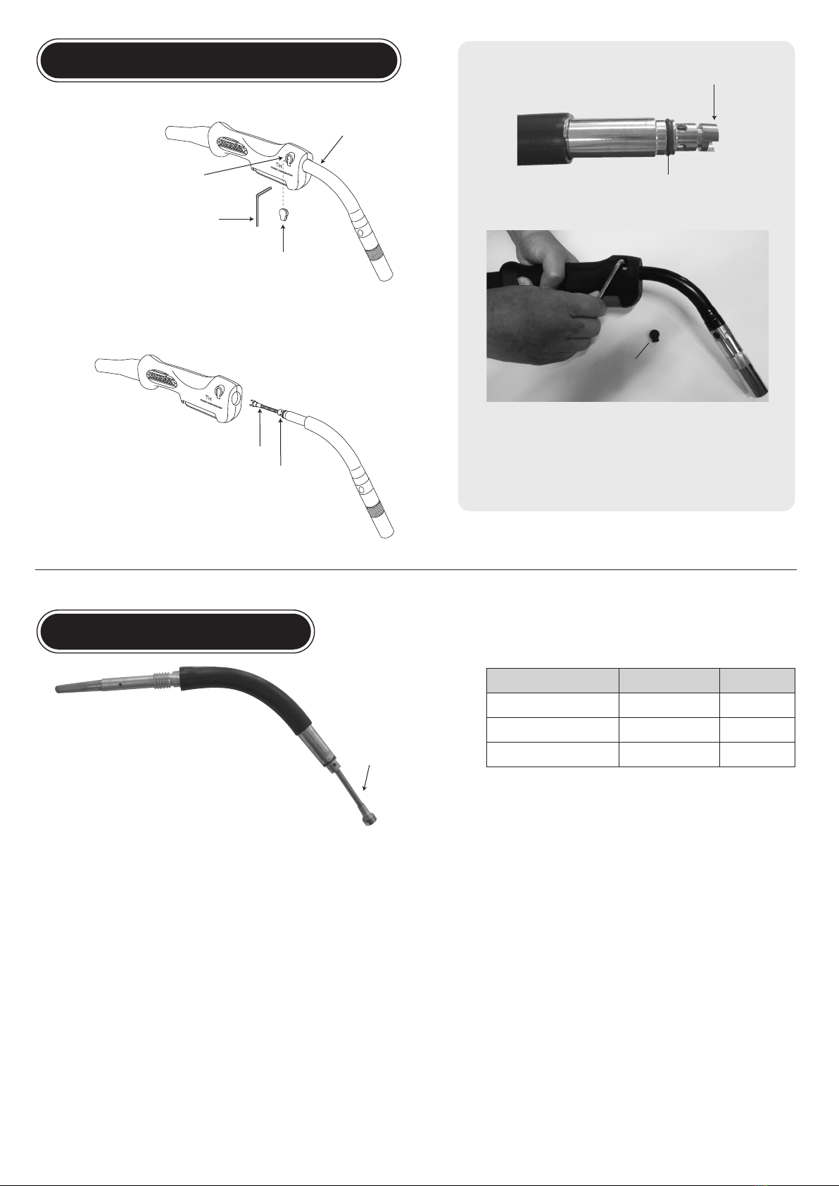
ReplacingtheTorchBody
ReplacingtheInnerTube
Usingahexagonwrenchloosenthesetscrewand
pulloutthetorchbody.
When inserting the new torch body always make
suretheinnertubeandO-ringareinplace.
Thensecurlytightenthesetscrew.
Ifwirefeedingbecomesunsteadyduetoinnertubewearoriscloggedwithwireshavings,rust
ordirt,pleaseremovethetorchbodyandreplacetheinnertube.
Pleasebesuretofullyinsertthetorchbodyandfirmly
tightenthesetscrew.
If inadequately tightened heat generation from poor
electricsupplyandgasleaksmayoccur.
InnerTube
O-Ring
InnerTube
CSH-35,50/TH-35,40,50
CSH-35F,50F/TH-35F,40F,50F
CSH-35L,50L/TH-35L,40L,55
InnerTube
〃
〃
PartNo.
036011
036350
050310
Item
NOTICE: To adjust the length of the inner tube cut from the front
endofthenewinnertubetosuitthelengthofthetorchbody.
THInsulatingRubber
TorchBody
SetScrew
HexagonWrench
THInsulatingRubber
O-Ring
InnerTube
4
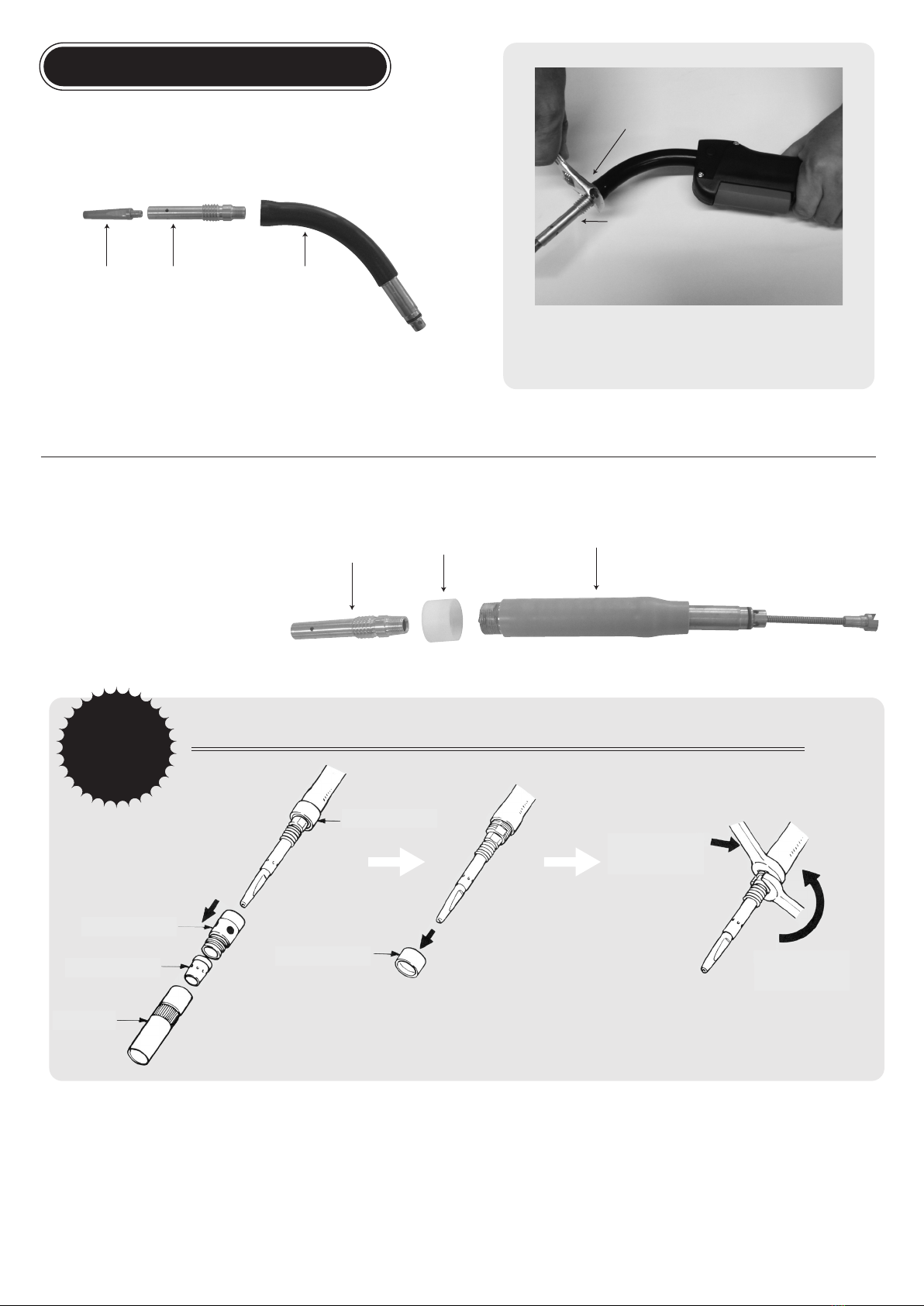
ReplacingtheTipBody
If damaged by heat or spatter please unscrew the tip body using a
wrenchandreplacewithanewone.
Whenremovingthetipbodyfrom
a flexible torch body be careful
nottodamagetheplasticcap.
■
CSH-35F,50F/TH-35F,50F
TipBody
Orifice
TorchBody
PlasticCap
FlexReplacingtheTipBody
Attentions
①Removethenozzle,orifice,insulatorand
plasticcapinorder.
②Holdthetorchbodywithawrenchandremove
thetipbodybyturningitcounterclockwisewith
anotherwrench.
③When replacing the tip body, be
suretoholdthetorchbodywitha
wrenchaswellasremovalproce-
dure and tighten the tip body and
puttheplasticcapback.
④Wheneverattachingordetachingthetipbodyalwaysbe
suretoholdthetorchbodywithawrench.Aftersecurely
tighteningthetipbodyscrewontheplasticcap.
Tip TipBody TorchBody
TipBody
TightenSecurely
NOTICE:Toavoidexcessheatgenerationandunstable
arc please be sure to always tighten the tip body
securely.
Insulator
Nozzle
PlasticCap
PlasticCap
5
ReplacingtheTipBody
If damaged by heat or spatter please unscrew the tip body using a
wrenchandreplacewithanewone.
Whenremovingthetipbodyfrom
a flexible torch body be careful
nottodamagetheplasticcap.
■
CSH-35F,50F/TH-35F,50F
TipBody
Orifice
TorchBody
PlasticCap
FlexReplacingtheTipBody
Attentions
①Removethenozzle,orifice,insulatorand
plasticcapinorder.
②Holdthetorchbodywithawrenchandremove
thetipbodybyturningitcounterclockwisewith
anotherwrench.
③When replacing the tip body, be
suretoholdthetorchbodywitha
wrenchaswellasremovalproce-
dure and tighten the tip body and
puttheplasticcapback.
④Wheneverattachingordetachingthetipbodyalwaysbe
suretoholdthetorchbodywithawrench.Aftersecurely
tighteningthetipbodyscrewontheplasticcap.
Tip TipBody TorchBody
TipBody
TightenSecurely
NOTICE:Toavoidexcessheatgenerationandunstable
arc please be sure to always tighten the tip body
securely.
Insulator
Nozzle
PlasticCap
PlasticCap
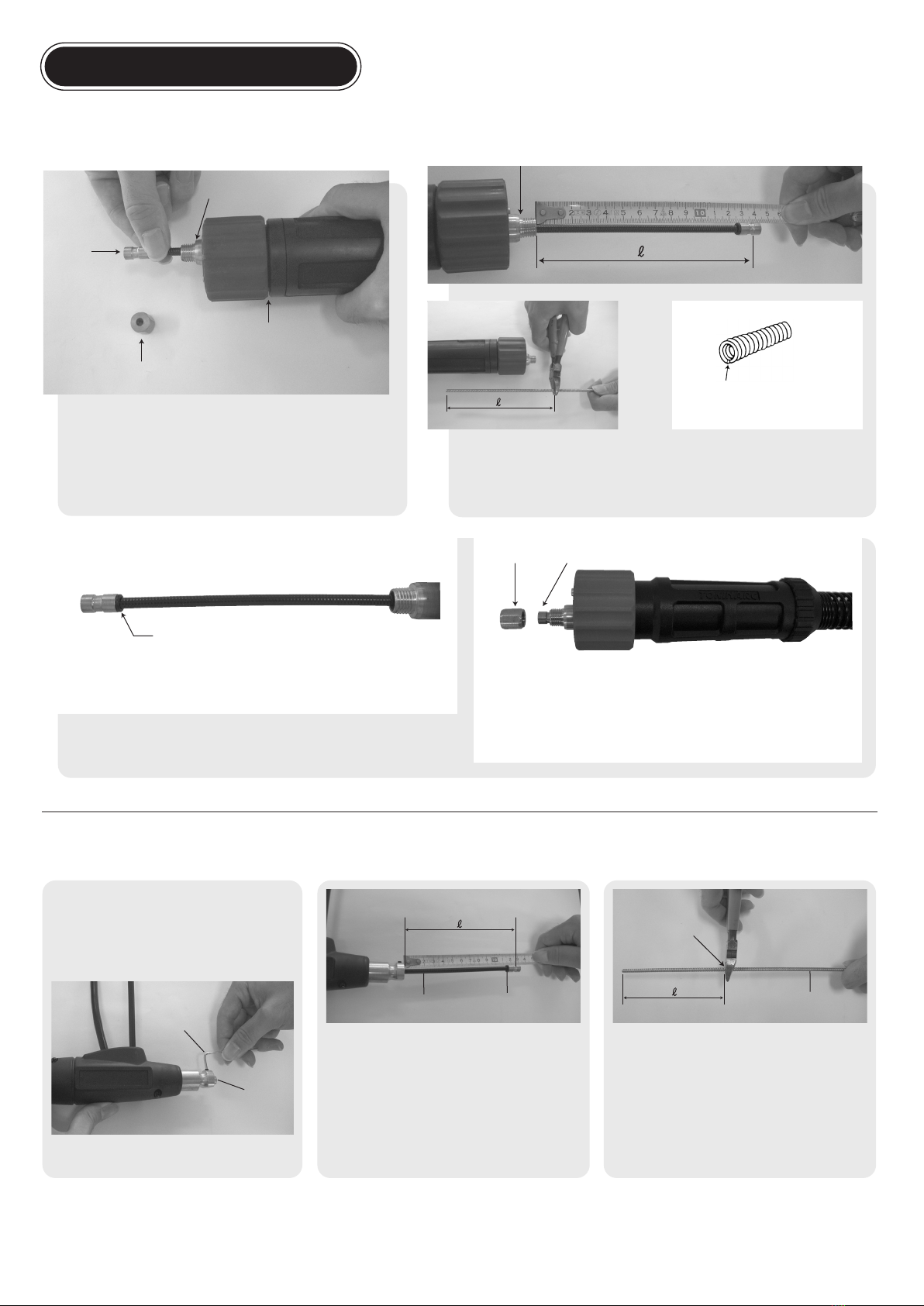
ReplacingtheLiner
Ifwirefeedingbecomesunsteadyduetolinerwearoriscloggedwithwire
shavings,rustordirt,pleasereplacethelinerbythefollowingprocedure.
ライナ
ForTokinConnection
ForDirectConnection
ElectricConnector
LinerNut
TorchAdapter
Liner
①Placethecableinastraightline.
②Unscrewthelinernut.Rotatethetorchendcounterclockwise
untilthelinerfittingcanbeeasilygrasped.Pullouttheliner. ③Fullyinsertthenewlinerinto the cable.Measure thelengthLwhichprotrudes
from the end. Pull the liner out and cut off the same lengthLfrom the front.
Aftercutting,fileoffanyburrededges.Alonglinerwillcausegasleaks,whereas
ashortlinerwilldisruptwirefeeding.
ElectricConnector
Fileoffanyburrededges.
①Placethecableinastraightline.
②Using a hexagon wrench loosen the set
screwontheelectricsupplyfitting.Rotatethe
torch end counterclockwise until the liner
fittingcanbeeasilygrasped.Pullouttheliner.
④Without twisting carefully insert the length-ad-
justed liner into the cable. Because the O-ring
at the front of the liner fitting prevents gas
leaks, please be careful when measuring. A
long liner will cause gas leaks, whereas a
short liner will disrupt wire feeding. Using a
hexagon wrenchtightenthesetscrewonthe
electricsupplyfitting.
LinerNut Liner
Hexagon
Wrench
Liner
Liner LinerO-Ring Liner
CuttingPosition
LinerO-Ring
Withouttwistingcarefullyinsertthelength-adjustedlinerintothecable.
④Without twisting carefully insert the length-adjusted liner into the cable.
BecausetheO-ringatthefrontofthelinerfittingpreventsgasleaks,please
becarefulwhenmeasuringForDirectConnection.
After setting the liner as illustrated, tighten the liner nut by hand.
Hand-tightening will be enough. Do not use a wrench, pliers, or other
tools.
③Fullyinsert thenewlinerintothecable.Measure
thelengthLwhichprotrudesfromtheend.Pull
thelineroutandcutoffthesamelengthLfrom
thefront.Aftercutting,fileoffanyburrededges.
6
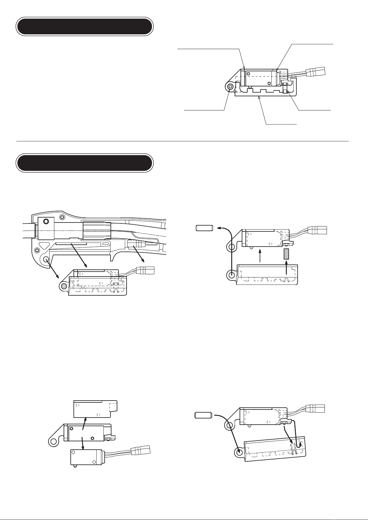
THMicroSwitchAssembly
TheTHseriesusesadust-proofmicroswitch.
The switch lever and all other parts are joined together into one
assembly.
ReplacingtheMicroSwitch
①Disconnect the wire terminal connections from the cable and
detachtheswitchassemblyfromthehandle.
②Pullouttheswitchleverpinandtheswitchleverwilldetach.
Note:Becarefulnottolosethespring.
③Removethemicroswitchretentionplatetotakeoutthemicro
switch.
④Insertthenewmicroswitchintheoppositesequence.
〔Built-inSpring〕
(1)With the switch lever leanedupward place the springinto
theprotrusion.
(2)Hook the micro switch holder tail end into the switch
leverinteriorandpressthespringdownuntilsecure.
(3)Match the front end and insert the pin to bind everything
together.
Note:Please tryoperatingtheswitch toconfirmtheassembly
iscorrect.
MicroSwitchHolder
MicroSwitchRetentionPlate
MicroSwitch
(Dust-ProofType)
SwitchLeverPin
SwitchLever
SwitchSpring
7

THMicroSwitchAssembly
TheTHseriesusesadust-proofmicroswitch.
The switch lever and all other parts are joined together into one
assembly.
ReplacingtheMicroSwitch
①Disconnect the wire terminal connections from the cable and
detachtheswitchassemblyfromthehandle.
②Pullouttheswitchleverpinandtheswitchleverwilldetach.
Note:Becarefulnottolosethespring.
③Removethemicroswitchretentionplatetotakeoutthemicro
switch.
④Insertthenewmicroswitchintheoppositesequence.
〔Built-inSpring〕
(1)With the switch lever leanedupward place the springinto
theprotrusion.
(2)Hook the micro switch holder tail end into the switch
leverinteriorandpressthespringdownuntilsecure.
(3)Match the front end and insert the pin to bind everything
together.
Note:Please tryoperatingtheswitch toconfirmtheassembly
iscorrect.
MicroSwitchHolder
MicroSwitchRetentionPlate
MicroSwitch
(Dust-ProofType)
SwitchLeverPin
SwitchLever
SwitchSpring
12-2
12-1
13-1
THSeries
TorchAdapter
THArcShield
THSwitchGuard
Adapter
■PartsList
■Replacetheguidetube
1.Pushbyscrewdliverheadand
pulloutguidetube.
2.Insertnewadapterguidetubefrom
thesharpenedtip.
THTorchHook
M4×16screws(※part)switchtoM4×25screws
Hangthetorchonthewall Preventmalfunctionofswitchlever
THOpptionalParts
※
※
※
Protectstheoperator'shandfrom
direct exposure to heat, sparks,
andspatter
AdapterGuideTube
WireFeederAdapter
8

■PartsList
1.Nozzle
PartNo.
038040
038041
038042
001002
001003
001008
001009
001004
001007
001001
001010
001005
001012
001015
Item
TL-18,20Φ13
TL-18,20Φ16mm
TL-18,20NarrowNozzle
Φ16(350A)73L
Φ12(350A)73L
Φ18(350A)73L
Φ16(350Athick2.5t)
NNarrowNozzle(350A)
350AArcSpotNozzle
Φ19(500A)88L
Φ16(500A)88L
Φ13(500A)88L
Φ19(500A)84L
Φ16(500A)84L
9.Handle
PartNo.
077071
Item
THHandle
10 .SwitchLever
PartNo.
077072 THSwitchLever
12 .MicroSwitch
PartNo.
077073
077074
077075
12-1:
12-2:
THMicroSwitch
THMicroSwitchHolder
THMicroSwitchPlate
13 .HexagonSocketBolt
PartNo.
020123
07707613-1:
TL/TH
THBlock
15 .AdaptorNut
PartNo.
020002 AdapterNut
11 .SwitchSpring
PartNo.
032016 CSH/TH/TLSpring
14 .PowerAdapter
PartNo.
020001 PowerAdapter
16 .LinerNut
PartNo.
020003 TL/CSH/TH/CP
17 .Screw
PartNo.
020004 TL/CSH/TH/CP
21 .PowerCable
PartNo.
087030
087040
087045
087050
087060
088030
088040
088045
088050
088060
089030
089040
089045
089050
089060
090030
090040
090045
090050
090060
Item
TH-353m
TH-354m
TH-354.5m
TH-355m
TH-356m
TH-403m
TH-404m
TH-404.5m
TH-405m
TH-406m
TH-503m
TH-504m
TH-504.5m
TH-505m
TH-506m
TH-553m
TH-554m
TH-554.5m
TH-555m
TH-556m
4.ContactTip
PartNo.
002003
002017
002004
002018
002019
002013
002503
002502
002501
Item
NTip1.2
NTip1.4
NTip1.6
NAlminumTip1.2
NAlminumTip1.6
NFluxTip1.2
NMAGTip1.2
NMAGTip1.4
NMAGTip1.6
A(350,450A)
B(500A)
2.Orifice
PartNo.
003001
003002
Item
3.Insulator
PartNo.
004001
004002
Item
8.TorchBodyO-Ring
PartNo.
036030
Item
5.TipBody
PartNo.
036001
036002
Item
CSH-35,50/TH-35,40,50
CSH-35F,50F/TH-35F,40F,50F
CSH-35L,50L/TH-35L,40L,55
6.InnerTube
PartNo.
036011
038072
050310
Item
CSH-35,50/TH-35,40,50
CSH-35K/TH-35K
CSH-35F,50F/TH-35F,40F,50F
CSH-35G/TH-35G,40G
CSH-35L,50L/TH-35L,40L,55
CSH/TH(S-9)
7.TorchBody
PartNo.
036022
038004
036024
036051
050302
Item
L(500A)
S(350A)
L(500A)
S(350A)
Item
Item
Item
Item
Item
Item
19 .TeflonLiner
PartNo.
0431030
0441030
TL/TH-351.23m
CSH/TH1.63m
Item
Item
Item
18 .AdapterO-Ring
PartNo.
020005 TL/CSH/TH/CP
Item
19 .Liner
PartNo.
037003
037004
037046
037005
037006
037007
037008
037047
037009
037050
036044
036043
036047
036042
036041
TL/CSH-35/TH-351.0-1.23m
TL/CSH-35/TH-351.0-1.24m
TL/CSH-35/TH-351.0-1.24.5m
TL/CSH-35/TH-351.0-1.25m
TL/CSH-35/TH-351.0-1.26m
CSH-35/TH-35,401.43m
CSH-35/TH-35,401.44m
CSH-35/TH-35,401.44.5m
CSH-35/TH-35,401.45m
CSH-35/TH-35,401.46m
CSH-45,50/TH-50,551.2-1,63m
CSH-45,50/TH-50,551.2-1,64m
CSH-45,50/TH-50,551.2-1,64.5m
CSH-45,50/TH-50,551.2-1,65m
CSH-45,50/TH-50,551.2-1,66m
Item
20 .LinerO-Ring
PartNo.
036035
036037
S-4
S-5
Item
23 .AdapterguideTube
PartNo.
020040
020041
020043
020044
Item
N,M,Mc
D
B
H
24 .SwitchLeverPin
PartNo.
077077
Item
TH
25 .InsulationRubber
PartNo. Item
PartsforDAdapter
PartNo.
020050
020054
020052
020053
Item
PowerCableAdapter500A
PowerCableAdapter350A
OutletGuide
GuideAdapter
Options
PartNo.
077079
077080
077081
Item
THArcShield
THSwitchGuard
THTorchHook
077077 TH
22 .Adapter
PartNo.
020030
020029
020031
Item
N
D(350A)
D(500A)
9

■PartsList
1.Nozzle
PartNo.
038040
038041
038042
001002
001003
001008
001009
001004
001007
001001
001010
001005
001012
001015
Item
TL-18,20Φ13
TL-18,20Φ16mm
TL-18,20NarrowNozzle
Φ16(350A)73L
Φ12(350A)73L
Φ18(350A)73L
Φ16(350Athick2.5t)
NNarrowNozzle(350A)
350AArcSpotNozzle
Φ19(500A)88L
Φ16(500A)88L
Φ13(500A)88L
Φ19(500A)84L
Φ16(500A)84L
9.Handle
PartNo.
077071
Item
THHandle
10 .SwitchLever
PartNo.
077072 THSwitchLever
12 .MicroSwitch
PartNo.
077073
077074
077075
12-1:
12-2:
THMicroSwitch
THMicroSwitchHolder
THMicroSwitchPlate
13 .HexagonSocketBolt
PartNo.
020123
07707613-1:
TL/TH
THBlock
15 .AdaptorNut
PartNo.
020002 AdapterNut
11 .SwitchSpring
PartNo.
032016 CSH/TH/TLSpring
14 .PowerAdapter
PartNo.
020001 PowerAdapter
16 .LinerNut
PartNo.
020003 TL/CSH/TH/CP
17 .Screw
PartNo.
020004 TL/CSH/TH/CP
21 .PowerCable
PartNo.
087030
087040
087045
087050
087060
088030
088040
088045
088050
088060
089030
089040
089045
089050
089060
090030
090040
090045
090050
090060
Item
TH-353m
TH-354m
TH-354.5m
TH-355m
TH-356m
TH-403m
TH-404m
TH-404.5m
TH-405m
TH-406m
TH-503m
TH-504m
TH-504.5m
TH-505m
TH-506m
TH-553m
TH-554m
TH-554.5m
TH-555m
TH-556m
4.ContactTip
PartNo.
002003
002017
002004
002018
002019
002013
002503
002502
002501
Item
NTip1.2
NTip1.4
NTip1.6
NAlminumTip1.2
NAlminumTip1.6
NFluxTip1.2
NMAGTip1.2
NMAGTip1.4
NMAGTip1.6
A(350,450A)
B(500A)
2.Orifice
PartNo.
003001
003002
Item
3.Insulator
PartNo.
004001
004002
Item
8.TorchBodyO-Ring
PartNo.
036030
Item
5.TipBody
PartNo.
036001
036002
Item
CSH-35,50/TH-35,40,50
CSH-35F,50F/TH-35F,40F,50F
CSH-35L,50L/TH-35L,40L,55
6.InnerTube
PartNo.
036011
038072
050310
Item
CSH-35,50/TH-35,40,50
CSH-35K/TH-35K
CSH-35F,50F/TH-35F,40F,50F
CSH-35G/TH-35G,40G
CSH-35L,50L/TH-35L,40L,55
CSH/TH(S-9)
7.TorchBody
PartNo.
036022
038004
036024
036051
050302
Item
L(500A)
S(350A)
L(500A)
S(350A)
Item
Item
Item
Item
Item
Item
19 .TeflonLiner
PartNo.
0431030
0441030
TL/TH-351.23m
CSH/TH1.63m
Item
Item
Item
18 .AdapterO-Ring
PartNo.
020005 TL/CSH/TH/CP
Item
19 .Liner
PartNo.
037003
037004
037046
037005
037006
037007
037008
037047
037009
037050
036044
036043
036047
036042
036041
TL/CSH-35/TH-351.0-1.23m
TL/CSH-35/TH-351.0-1.24m
TL/CSH-35/TH-351.0-1.24.5m
TL/CSH-35/TH-351.0-1.25m
TL/CSH-35/TH-351.0-1.26m
CSH-35/TH-35,401.43m
CSH-35/TH-35,401.44m
CSH-35/TH-35,401.44.5m
CSH-35/TH-35,401.45m
CSH-35/TH-35,401.46m
CSH-45,50/TH-50,551.2-1,63m
CSH-45,50/TH-50,551.2-1,64m
CSH-45,50/TH-50,551.2-1,64.5m
CSH-45,50/TH-50,551.2-1,65m
CSH-45,50/TH-50,551.2-1,66m
Item
20 .LinerO-Ring
PartNo.
036035
036037
S-4
S-5
Item
23 .AdapterguideTube
PartNo.
020040
020041
020043
020044
Item
N,M,Mc
D
B
H
24 .SwitchLeverPin
PartNo.
077077
Item
TH
25 .InsulationRubber
PartNo. Item
PartsforDAdapter
PartNo.
020050
020054
020052
020053
Item
PowerCableAdapter500A
PowerCableAdapter350A
OutletGuide
GuideAdapter
Options
PartNo.
077079
077080
077081
Item
THArcShield
THSwitchGuard
THTorchHook
077077 TH
22 .Adapter
PartNo.
020030
020029
020031
Item
N
D(350A)
D(500A)
MEMO
MEMO
10

InstructionManual
CO2MAGWeldingTorches
CO2MAGWeldingTorches
1509 Okubo-cho, Nishi-ku, Hamamatsu-shi,
Shizuoka Japan 432-8006
TEL : +81-53-485-5252 FAX : +81-53-485-5680
E-mail [email protected]
URL http://www.tokinarc.co.jp
Please read this instruction manual
before using the product.
Please be sure to deliver this instruction manual
to the end user of this product.
TH Series
400amp.
TH-40
TH-40F
TH-40L
TH-40G
Semi-AutomaticTorches
350amp.
TH-35
TH-35K
TH-35F
TH-35L
TH-35G
500amp.
TH-50
TH-50F
TH-50L
550amp.
TH-55
This manual suits for next models
13
Table of contents
Popular Welding System manuals by other brands


GÜDE
GÜDE SG 120 A Translation of the original instructions

Leister
Leister WELDPLAST S2 operating instructions

Kemppi
Kemppi KEMPOMAT 320 KEMPOMAT 320C operating instructions

Lampert
Lampert PUK04 operating manual

ESAB
ESAB Aristo MechTig 3000i instruction manual

Lincoln Electric
Lincoln Electric Prism 13264 Operator's manual


