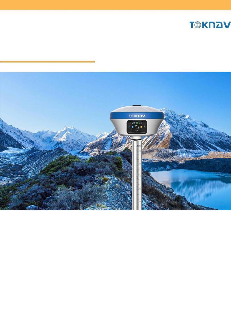
TOKNAV T10Pro User manual


1. Introduction to the T10Pro 01-03
03-04
05-32
2. PCR100 Data Controller
3. SurPro software operation
32-34
35-38
4. Tilt measurement
5. Host Registration and
Software Licensing

1. Introduction to the T10Pro
1.1. Exterior description
A. Satellite Indicator Light;
B. Power button;
C. 7 Pin data connector (Serial/External Power);
D. SIM card compartment;
E. USB Type C Interface;
F. The loudspeaker hole;
G. UHF Antenna Port.
1.2. Operating Instructions
1.2.1. SIM card installation
Opening the dust plug;
Install the SIM card according to the indication
(SIM card chip is facing up, the notch is facing
the receiver);
Cover with dust plug.
A
C
F
B
E
G
Figure 1 Figure 2
D
01 02

1.2.2. The meaning of the instrument keys
and indicator lights
One flashing light represents
0 to 33% battery level (Figure 4).
Two flashing lights represent 33%
to 66% battery level (Figure 5).
Projects Function Role or status
Battery level broadcast
Switch
Short press to broadcast power
Long press to turn on/off;
Date Chain Light
Rover mode: Blink when receiving
differential data;
Base mode: Blink when sending
differential data;
Satallite Light
Rover/base station: 1 second
interval flashing in the
positioning state;
Static mode: flashing according to
sampling frequency.
1.2.3. Power on and off
1.2.4. Charging equipment
Power on: Press and hold the power button until the voice
prompts "Booting" and release, the device starts up, and
the panel lights flash until the voice prompts "Boot
completed" and the device is turned on.
Shutdown: Press and hold the power button until the
voice prompts "shutdown", the panel lights are all off,
and the device is shut down.
Forced shutdown: When the device cannot be shut down
normally due to an unexpected failure, press and hold the
power button for 10 seconds to power off the device.
The red light of the power supply is always on when
charging, and the green light is always on when charging
is complete.
The host supports MTK PE1.1/2.0 and PD protocol fast
charging. Using a fast charging adapter for charging can
shorten the charging time.
Note: For the safety of your device, please use the
standard adapter in the package, or a brand adapter that
complies with 3C certification to charge the host.
Note: In the off state, short press the power button, and the
power information can be calculated according to the
number of lights on.
Three flashing lights represent 66%
to 100% battery level (Figure 6).
Figure 3
Figure 4
Figure 5
Figure 6
01 02

with measuring handbook software. T10pro has profes-
sional IP68 grade protection, which is suitable for harsh
outdoor environments. The large-capacity lithium battery
can guarantee more than 10 hours of field work and
complete multiple measurement tasks throughout the
day (Figure 8).
1.2.5. WEB access
The receiver supports Web access to the built-in page for
viewing host information and upgrading firmware. The
host's WIFI hotspot is turned on by default, and the
hotspot name is the machine number SN. Users can
access the hotspot with mobile phones, tablets, PCs and
other devices, and then enter the URL: 10.10.10.10 in the
browser to access the receiver Web UI. As shown in
Figure 7.
Octa-core 2.0GHz CPU;
4GB RAM + 64GB ROM;
5 megapixel front + 13 megapixel rear camera;
IP68 protection, waterproof/shockproof/dustproof;
Wi-Fi, Bluetooth, NFC;
4G all-network support;
7000 mAh battery with 14 hours of battery life;
Universal Type-C connector;
Charging time: less than 4 hours (fast charging).
2. PCR100 Data Controller
The PCR100 TD-LTE wireless computer is a rugged,
multi-function wireless computer designed with a 5-inch
sunlight readable HD touch screen and alphanumeric
keypad, equipped with a powerful octa-core processor
and Android operating system for perfect adaptability
2.1 Overview
2.2 Key features
Figure 7
Figure 8
03 04

You can also connect the T10Pro through the NFC
function of the mobile phone, put the NFC area of the
mobile phone close to the (Figure 11), and in the
pop-up window, click OK to connect (Figure 12).
Run the SurPro measurement software, execute [Config-
device type, as shown in Figure 10, click [Search for
Bluetooth devices], find the Bluetooth name of the
corresponding device in the Bluetooth device list (the
default is the host machine number), click [Start Connect].
The connection progress box will pop up, indicating that
the connection is in progress, and after the connection is
successful, it will prompt that the connection is successful.
3. SurPro software operation
3.1 Connecting equipment
Figure 9 Figure 10 Figure 12
Figure 11
05 06

new project, enter the project name, others are additional
information, which can be left blank, or filled in according
to the actual data, and click [OK] (Figure 14). Jump to the
coordinate system parameter interface. In China, the
ellipsoid parameters are CGCS2000 by default, and the
projection method is Gaussian projection.
You can set the coordinate system for other parameters
according to the actual operation requirements.
3.2 New Project
Copy the data files to be imported to the SurPro Survey
select the corresponding file format and angle format to
import (Figure 15,16 ).
3.3 File import
Figure 15 Figure 16Figure 13 Figure 14
07 08

angle format and file format, then click [Export]. Then we
select the output file storage path, and click [Export], the
data file is exported successfully (Figure 17, 18).
3.4 Document export
Figure 17 Figure 18
Example: four-parameter conversion.
3.5.1 Correctly configure the mobile station to obtain a
fixed state, click [Collect Point] to measure two known
3.5 Parameter conversion
The control point
North: 2562983.7364
East:441751.8702
Height:18.6503
Figure 19
09 10

click the […] button in the lower right corner, select
[Calculate Option] in the pop-up window (Figure 21), and
set the parameter settings (Figure 22).
Figure 20 Figure 21 Figure 22
measurement points from the point library (Figure 24),
and add two sets of data. Then click Calculate Four
Parameters(Figure 25), scroll down the parameter report
page, as shown in the frame, the scale should be infinitely
close to 1. After checking, click [Apply] to apply the
coordinate transformation parameter results to the
project (Figure 26).
3.5.3 Return to the previous page, click [Add] in the lower
left corner (Figure 23), input the coordinates of the known
control points in the local coordinate system, perform
point measurement in the geodetic coordinates of the
source coordinate system or select the coordinates of the
the control point
the collect point
Figure 23 Figure 24
11 12

-
ter calculate] below (Figure 27). Enter the known plane
coordinates, and click on the geodetic coordinates for
more acquisition methods, which include "positioning
acquisition" and "point library acquisition", after the input
is completed, click [Cal.] (Figure 28). After the calculation
is completed, click [OK] to enable the base station transla-
3.6 Point Calibration
Figure 27 Figure 28 Figure 29
Note: In the parameter report, the plane conversion
parameters and elevation conversion parameters can be
checked.
The scale parameter is generally infinitely close to 1. If the
value does not match, please check the operation
whether there is any operation error or coordinate error
in the process.
Figure 25 Figure 26
13 14

[Built-in Network], [Mobile Phone Network] or [Built-in
Radio] for the data link mode.
3.7.1 Select [Built-in Network], for a specific SIM card
(private network card or some IoT cards), you need to fill
in the corresponding APN parameters, the general SIM
card can be left blank here, and then fill in the
corresponding CORS information (or from the CORS list
Select from the library), click to obtain the access point
list (Figure 30). Because it is in the parameter setting
3.7 Rover mode setting
Figure 30 Figure 31
3.7.2 Select [Mobile Phone Network], after filling in the IP,
port, user name and information of the CORS station, you
can directly use the mobile network to obtain the access
point list for selection (Figure 32).
stage, the internal network of the host has not been
successfully started, and the access point cannot be
obtained at this time, you can first use the mobile
network to obtain the access point to select. Then click
[OK] to complete the setting of the working mode (Figure
31).
Figure 32
15 16

3.7.3 Select [Built-in radio], you need to connect the UHF
radio antenna under the host (Figure 33), and then select
the corresponding radio frequency and communication
protocol (Figure 34).
Figure 33 Figure 34
value, altitude cutoff angle, sampling interval, antenna
information and other parameters, click [OK] to start
storing static data (Figure 35, 36).
3.8 Static mode setting
R0
h0
height of pole
h(slope
height to line)
to phase center
Figure 35
Figure 36
17 18

Log in to the receiver web page (see 1.2.5 for details), click
[File] (Figure 37). Find the folder corresponding to the
time to download the static data (Figure 38).
3.8.2 Static file downloads
Figure 37
Figure 38
Network], [Built-in Radio] or [External Radio] for the data
link mode.
(private network card or some IoT cards), you need to fill
in the corresponding APN parameters, and the general
SIM card can be left blank, and then fill in the correspond-
3.9 Base station mode setting
Figure 39
19 20

radio antenna under the host (Figure 40), and then select
the corresponding radio frequency and communication
protocol (Figure 41).
external large radio.
Prepare the following tools: Harxon radio (eRadio), radio
antenna, big 7-core radio connection cable L0614-15,
Figure 40 Figure 41
T10Pro base station, T10Pro rover station, power supply
(12V), tripod.
2 Instrument set-up.
(1) Erection of base station.
antenna higher, and keep the distance of more than three
meters between two tripods.
antenna, and hang the radio on the tripod. The radio
Figure 42
Baso station 7-core 0b plug
7-core radio
connecting wire
Big radio antenna
Extension rod
Big radio
Tripod
12V battery
L0614-15
5-core 1b plug
Red dot mark
Red dot mark
TNC male
21 22

antenna interface is connected to the antenna port of
Harxon radio (eRadio), the five-core head of the
seven-core radio cable is connected to the five-core
interface of Harxon radio (eRadio), and the seven-core
head of the seven-core radio cable is connected to the
T10Pro base station IOIOI Seven-core interface, the
crocodile clip of the seven-core radio cable is connected
to the positive and negative poles of the power supply
(red is positive and black is negative). After connecting,
you can see that the Harxon radio (eRadio) is turned on,
and the POWER light is on (Figure 42).
external radio data link, and set the serial port baud rate
to 115200 (Figure 43).
Figure 43
BT
12.3V
014 464.12500
RX/TX Frequency/channel
465.12500
*
RX/TX
POWER
BT
12.3V
014 464.12500
465.12500
*
RX/TX
POWER
BT
10.1V
115200
Serial Baudrate
*
RX/TX
POWER
Harxon radio (eRadio) button interface, set the radio
the protocol, and set the serial port baud rate to 115200
(Figure 44 and 45). (The serial port baud rate needs to be
consistent with the base station receiver for normal
communication).
indicating that data is being sent normally (Figure 46).
RX/TX Frequency/channel
Figure 44
Figure 45
Figure 46
23 24

The T10Pro rover station is powered on and fixed on the
carbon fiber centering pole (Figure 47). During measure-
ment, set the working mode to built-in radio, set the
for the protocol (Figure 48). (Note: The frequency, air
baud rate and eRadio must be the same, so that the radio
Figure 47
signal can be received. and the T10Pro needs to be
connected to the radio antenna as a mobile station).
After the differential light of the mobile station flashes
and the SurPro measurement APP "fixed", the measure-
ment and sampling work can be carried out.
The SurPro App displays the following screen (Figure 48).
Figure 48 Figure 49
2625

3.10 Collect Point
In the top column of the point measurement interface
(Figure 51 and 52), you can view the current status
information of the host (H: horizontal accuracy, V:
elevation accuracy, host solution status, differential delay,
Figure 50 Figure 51
Figure 52
S: number of available satellites, V: number of visible
satellites, power information). The bottom column of this
interface displays the point name currently to be collect-
ed, as well as the antenna height parameter settings.
There are six display columns at the bottom of this
interface. The display order and display content of these
display columns can be set according to your own needs
(The stored coordinates of the measurement will not
change), click on a display column, you can replace it with
other display content.
As shown in Figure 53, click the display bar below, a
selection box will appear, and you can select the content
Figure 53
Figure 54
2827

to be displayed. The contents that can be displayed here
mainly include: north coordinate, east coordinate,
elevation, longitude, latitude, geodetic height, speed,
time, upper gear slant distance, upper gear horizontal
distance, upper point height difference and base station
distance (Figure 54).
Enter the [Collect Point] interface (Figure 55), set the
antenna information in the upper right, click the "+" icon
the icon to see the point data (Figure 56).
Figure 55 Figure 56
Collect point, line, area and other data.
Quick collection points.
The meaning of each icon in the point measurement
page is as follows:
Control point measurement: At present, RTK technology can
be applied to primary and secondary traverse, root traverse
measurement and root elevation measurement. Since RTK
data has certain contingency, we have implemented the
function of control point measurement to improve the
reliability of the data.
Set the acquisition parameters for the control point measure-
ment.
Photo taking: the measurement site is photographed and
comments can be added.
Locate: Click on the locate icon to locate the map to the
current device location.
Full view: Click on the full image icon to display all measure-
ment points in the view.
Settings: Set the current acquisition parameters, including
state limit, HRMS limit, VRMS limit, PDOP limit, delay limit,
and smoothing points.
View: View the point coordinates of the current project
"Coordinate Management Library", which is the same as the
"Measurement Data" function in "Project".
3029

3.11 Stake Point
flag icon on the upper right to enter the stakeout point
library (Figure 58). Click the "..." icon in the lower right
corner to import the point just measured from the
measurement point library and perform the stakeout
can see the distance between the current coordinate
point and the known point (Figure 60).
Figure 57 Figure 58
4. Tilt measurement
Tilt measurement requires the host with inertial naviga-
tion function. The host with this function can do:
1. It can ensure that the accuracy of the host is maintained
within 2cm in the 60° tilt range;
2. The calibration process is simple, just shake the center-
ing rod back and forth in place;
3. Supports centering rod calibration to eliminate
measurement errors caused by the curvature of the
centering rod.
Figure 59 Figure 60
31 32

4.1 Operating instructions for the tilt
measurement function
corner to input the antenna height parameter (centering
pole height), and then turn on the tilt measurement icon
in the upper left corner to enable the tilt measurement
function. It is red when it is turned on (Figure 61). In the
continue to shake the centering rod back and forth, until
the tilt measurement icon turns green, and the tilt
measurement can be performed (Figure 62).
Figure 61 Figure 62
4.2 Use of the mainframe for tilt measurement
1. When the tilt measurement is turned on, sometimes
the tilt icon will change from green to red with movement
and rotation. At this time, the centering rod needs to be
shaken before the measurement, and the point can be
collected until the icon turns green;
2. During the tilt measurement process, the icon will turn
red when the inclination angle is greater than 60°, and the
accuracy of the points collected at this time cannot be
guaranteed to be 2cm;
3. When calibrating the centering rod, you need to set the
antenna height parameters first, otherwise the calibration
data will be wrong;
4. The initialization of the tilt measurement can only be
completed in the fixed solution state.
3433
Other manuals for T10Pro
1
Table of contents
Other TOKNAV Receiver manuals

